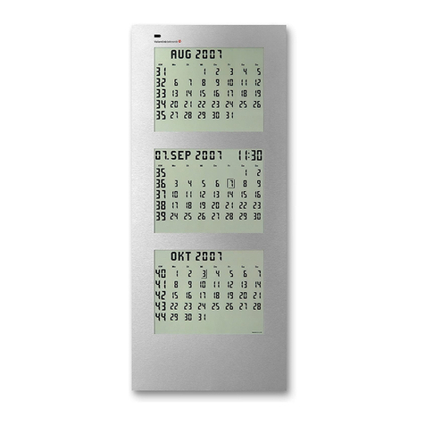
Valentin Elektronik C 210 Series User manual

Installation Instructions for the Digital Clock Series C 210
Page 1 of 2
C
Switching on the clock
Switch on the clock by means of the slide switch on the reverse side. All segments are now visible in the display for a short moment. The
clock switches automatically to radio reception (standard setting) for a maximum of 20 minutes. A constant blinking – in seconds - of the
radio waves at the radio tower symbol (top right in the display) indicates the reception of radio impulses. The radio tower remains
visible in case of satisfying reception, in case of poor reception it disappears. Thereby you can always control the quality of the
radio signal in each individual location. The clock requires 3 minutes of proper reception to indicate time and date.
What to do in case of radio interference
Sources of interference such as television, monitors, computers, metal walls or buildings with reinforced concrete walls may deteriorate
or even prevent reception. Check the receiving quality by watching the radio tower symbol. If the symbol disappears frequently, change
the location. Put the clock on your window sill where you will have the best reception. Avoid moving the clock during the reception
process!
In case of durable interference, there are four options to solve the problem:
1) Install the clock at another point in order to obtain best receiving results.
2) Change the clock to quartz-controlled mode. (see: Setting of the Operation Mode)
3) Keep the clock in the radio mode but set the current time manually. At 2 and 3 a.m. for 20 minutes each, the clock will attempt
synchronisation with radio operation. Sources of interference such as computers and neon lamps are disconnected at night
enabling improved reception. Should these attempts however not be successful, the life of the battery will be reduced due to
longer receiving hours at night.
4) An external aerial is optionally available. Connect this aerial to the clock and lay the aerial cable to a point providing improved
receiving quality. If the cable is not long enough, it can be extended up to max. 30 m. We recommend the cable: I-Y(ST)Y
2x2x0.6. This requires that you lay the shielding and the free lead to the 0-volt phase of the cable and connect it to the aerial. The
colour code of the aerial cable is as follows: White = +3V, green = data, brown = GND
Setting of the Operation Mode
Select the operation mode by pressing and holding the button T1 or T2 during the switch-on phase. Keep the relevant button pressed,
switch on the clock and then release the button.
T1 activates the quartz operation mode and deactivates the reception of the DCF-77 radio signal. Whereas T2 activates the DCF mode
and switches the clock to radio operation. The mode selected last will be saved and automatically activated when switching on the
clock again.
Manual Setting of Time and Date
By pressing the T1 button, when the clock is switched on, you get to the time and date setting, as well as to the temperature readout.
Preferably proceed as shown in the example below. By actuating the T2 button for entering hour →minute →day →month →
temperature →seconds (AC 150 only) you can make changes in the sequence as indicated. Press the T3 button for setting the desired
values. Finally save and terminate the settings by pressing the T1 button and the clock shows the changed values.
Setting Example
Press T1 once and set the hour by pressing T3. →Press T1 once and set the minute by pressing T3. →Press T1 once and set the day
by pressing T3. →Press T2 once and set the day by pressing T3. →Press T2 once and set the month by pressing T3. →
Press T2 once and set the year by pressing T3. →Press T2 once and a thermometer is shown in the display. Now you can set
the temperature indication to three different modes by means of the T3 button:
Caution: The temperature sensor is optional equipment. Without the sensor the clock shows only –0°C.
Athe temperature alternates with the date display, this means, the temperature (for 4 seconds) alternating with the
date display (for 6 seconds), will be depicted in the bottom line.
F fixed temperature display , this means no date is shown
No symbol “temperature readout off”, thus permanent date display
Press T2 once and an Ais shown in the display: And a blinking figure between 0 and 3. Here you can set the seconds readout (for
clock type AC 150 only) again with the T3 button. The values are indicated below:
Now you have finished the settings in this menu, and by pressing T2 you return to the beginning of the cycle, i.e. for setting the hour. To
terminate the settings, simply press the T1 button, while the seconds are automatically set to zero and from now on start counting. The
clock returns to the normal display mode and the adjustments you have just made are saved.
Value
Mode
0
Minute marks light up or extinguish
1
Seconds readout off, all marks light up
2
Minute marks always light up
3
Only the mark of the actual second fa
des out

Installation Instructions for the Digital Clock Series C 210
Page 2 of 2
Setting of the Time Zone
For the countries Germany, Austria, Switzerland, France, Benelux, the time is set in the factory to +1 hour to the world time (UTC =
Coordinated Universal Time) and needs to be changed only in case of deviating from this time, for example UK. For this, an offset
can be set, which adds to or deducts from the radio time received (corresponding to the world time). Thereby you have the option to use
the clock as part of a world clock or use it in adjacent time zones, where the DCF-// radio waves from Frankfurt are received.For this
purpose, press the T2 button in the normal mode of the clock, “Of” is shown in the display and the set offset in hours (the first two digits)
and in minutes (the last two digits). The offset can be set in a range of +/- 12 hours with the buttons T1 for +30 minutes and T3 for -30
minutes. By pressing the button T2 again, the setting is terminated and the new value is saved. For the operation in the above
mentioned time zones, ‘+0100’ is preset here.
Setting of the Summer/Winter Time Parameter
The settings of summer and winter time comply with the legal regulations, but may be altered in case these times change. By actuating
the T3 button in the normal mode of the clock, you reach the setting mode for the summer time. The clock now indicates ‘So’: for the
summer time and either ‘On’ (automatic switching for summer/winter time or ‘Of (no automatic switching). The button T3 serves to switch
from ‘On’ to ‘Of’ and vice versa. In the ‘Of’ setting, the clock returns to the normal mode after pressing the T2 button. If ‘On’ is selected,
the start and end of the summer time can be set after the T2 button has been pressed or by pressing T2 again, the standard settings can
be maintained. To achieve this, the T2 button is to be pressed several times (4x) until the normal display mode is shown.
Setting of the Start/End of the Summer Time
The clock change is always effected on a Sunday, i.e. two months and the respective Sundays have to be adjusted. First, the data for the
start of the summer time are queried. The clock indicates the month of the start as figure: the month blinks and can be set in a range
from 1 to 12 with the T3 button. By actuating T2 you select the respective Sunday: With the T3 button you can choose between the
figures from 1 to 4 and ‘L’. The figures indicate the Sunday, from the 1
st
to the 4
th
, while ‘L’ stands for the last Sunday of the month. By
pressing T2 you terminate the input of the start data. Now the data for the end of the summer time is to be adjusted in the same manner.
After completing the input, press T2 and the clock is reset in the normal mode and the data is saved. The standard factory setting for
Germany is the last Sunday in March for the start and the last Sunday in October for the end.
Secondary Clock Input
In case option ‘N’ was included in the order for the clock, a pole changing impulse of the master clock with a voltage ranging from 12 to
60 volt may be applied to the connecting field via the terminals 1 and 2.
External connector for DCF radio reception:
The DCF antenna can be connected on the reverse side of the clock. For this purpose, the respective DIP switches have to be adjusted
as defined in the table below. Radio reception is transmitted in frequency band 77.5 KHz.
Connecting of an External Temperature Sensor
An external sensor may be connected on the reverse side of the clock to be used instead of an internal sensor. In such a case, the
internal sensor will be deactivated.
External Power Source
An external direct voltage source may be supplied to the clock via the terminals 11 and 12. The voltage should not exceed 9 volt and not
fall below 6.5 volt.
Setting of the DIP Switch on the Reverse Side
DIP
-
Switch
ON
OFF
1,2
Internal DCF aerial activated
External DCF aerial activated
3,4,5
Language selection for day display, see separate
scheme
6
DCF signal inverted
DCF signal normal
7
Inverse date display (MM/DD)
Date display normal (DD/MM)
8
Suppress left
-
hand zeros for hours and
Depict left
-
hand zeros
Language Settings for the Days of the Week
DIP3
DIP4
DIP5
Language
Off
Off
Off
German
On
Off
Off
English
Off
On
Off
Dutch
On
On
Off
French
Off
Off
On
Spanish
Display of bold type correspond with our factory settings
Should you have any questions when installing the clock, please do not hesitate to contact us.
Valentin Elektronik GmbH Tel. +49 0(202) / 264 17 22
1
2
3
4
5
6
7
8
ON
DIP-Switches
ON - OFF
T1
T2T3
Connecting field
1
12
Backside
Table of contents
Other Valentin Elektronik Clock manuals
Popular Clock manuals by other brands

Bodet
Bodet Style 5S Hospital NTP Installation and operation manual

Hanhart
Hanhart PRISMA 200 Instruction book & guarantee

Marathon
Marathon Basics 64 operating instructions

UNIPRODO
UNIPRODO UNI CLOCK 05 user manual

Pyramid
Pyramid TimeTrax EZ prox ek PPDLAUBKN quick start guide

Acroprint
Acroprint ES700 Service manual