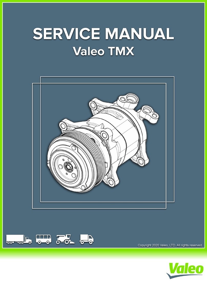
Valeo TM31 User manual

Copyright © 2017 Valeo Japan CO., LTD. All rights reserved.
SERVICE MANUAL
Valeo TM31 Compressor


- 1 -
The following warning signs are used in this service manual.
These are extremely important to ensure safe operation and to prevent body injuries and
property damage.
They must be fully understood before starting the air conditioner maintenance.
WARNING! Maintenance must be properly done to avoid serious injury risks.
CAUTION! Improper maintenance can result in injury or property damage.
WARNINGS
The following marks are used in this service manual to facilitate correct air conditioner
maintenance.
Advice Procedures necessary to ensure the best air conditioner maintenance.
Note Information to optimize the air conditioner maintenance.
MEANING OF MARKS
Foreword
This service manual has been elaborated to help
service personnel to provide efficient and correct
service and maintenance on the TM31 (formerly
called DKS 32) compressor (for HFC-134a) for auto-
motive air conditioning.
This manual includes the operation specifications,
procedures for disassembly, reassembly, and
inspection of the compressor.
The contents of this manual, including illustrations,
drawings and specifications were the latest available
at the time of printing.
Valeo Japan reserves the right to make changes in
specifications and procedures at any time without
notice.
VALEO JAPAN CO., LTD.

- 2 -
Contents
1- Product description ....................................................................... 3
2- Operation precautions ................................................................ 13
3- Handling instructions .................................................................. 14
Maintenance precautions ................................................................14
Work area ..............................................................................................14
Refrigerant handling ............................................................................14
Compressor handling .......................................................................15
Compressor removal ........................................................................15
Oil return operation .........................................................................16
Oil handling ......................................................................................16
Oil contamination ............................................................................17
Oil check ...........................................................................................17
Replacement of components ..........................................................18
Running-in operation .......................................................................19
Compressor running-in .........................................................................19
Magnetic clutch running-in ..................................................................19
Leak test ...........................................................................................20
Refrigerant charging ........................................................................20
Storing a repaired compressor ........................................................20
4- Troubleshooting .......................................................................... 21
Compressor troubleshooting ...........................................................21
Compressor troubleshooting tree ...................................................21
A/C cycle diagnosis by gauge pressure..........................................24
5- Tightening torques ...................................................................... 26
6- Service procedures - Magnetic clutch ........................................ 27
7- Service procedures - Shaft seal assembly ................................. 31
8- Service procedures - Cylinder heads .......................................... 34
9- Service tools ................................................................................ 39
10- Service parts ............................................................................. 43
- 3 -
1-Product description - Compressor
tc
te
Compressor
MODEL TM31
TECHNOLOGY Heavy Duty Swash Plate
DISPLACEMENT 313 cc (19.1 cu in) per rev.
NUMBER OF CYLINDERS 10
REVOLUTION RANGE 700-6,000 rpm (maximum peak : 7,000 rpm)
DIRECTION OF ROTATION Clockwise viewed from clutch
BORE 36 mm (1.42 in)
STROKE 30.7 mm (1.21 in)
SHAFT SEAL Lip seal type
LUBRICATION SYSTEM Lubrication by gear pump
REFRIGERANT HFC-134a
OIL (QUANTITY) ZXL 100 PG PAG OIL (DH-PS): 500 cc ( 30.5 cu in)
WEIGHT 9.5 kg (21 lb) (w/o Clutch w/o oil)
DIMENSIONS (with clutch)
Length - Width - Height
278.5 - 143 - 178 (mm)
10.94 - 5.63 - 7 (in)
MOUNTING Direct (side or base)
Valeo TM31 Application limits for HFC-134a
Saturated evaporating conditions
Saturated condensing conditions
PSIA PSIG oFMPaA MPaG oC
358 343 171 2.47 2.37 77
244 229 140 1.68 1.58 60
191 177 122 1.32 1.22 50
100 85 79 0.69 0.58 26
-17 -10 5 14 oC
0.05 0.10 0.25 0.37 MPaG
0.15 0.20 0.35 047 MPaA
1 14 41 57 oF
7 14 36 54 PSIG
22 29 51 69 PSIA
te
tc : Condensing temperature
te : Evaporating gas temperature

- 4 -
※The above specifications may vary with the compressor.
TYPE Electromagnetic single-plate dry clutch
RATED VOLTAGE 24V DC or 12 V DC
POWER CONSUMPTION 48 W maximum
STATIC TORQUE 78 N·m {8.0 kgf·m, 58 lbf·ft}
DIRECTION OF ROTATION Clockwise, viewed from clutch
WEIGHT Approx 4.5 kg {10 lb}
V-BELT TYPE V-groove (A or B) or V-ribbed (PK)
1- Product description - Magnetic clutch
Specifications*

- 5 -
1- Product description - Performance
The performance data below were measured under the following conditions:
• Compressor speed: 1450 rpm
• Suction gas temperature: 20oC
Conditions Cooling capacity Q (kW) & Power consumption P (kW)
Cond temp
(oC )
Pd
(MPaG)
Evap temp
(oC ) 12.5 10 7.5 5 0 -5 -10
Ps (MPaG) 0.35 0.32 0.28 0.24 0.19 0.15 0.10
40 0.91 P (kW) 4.04 3.94 3.82 3.74 3.49 3.20 2.88
Q (kW) 22.64 20.61 18.65 17.57 13.68 10.56 8.19
50 1.21 P (kW) 4.59 4.48 4.34 4.18 3.84 3.47 3.08
Q (kW) 21.22 18.70 16.54 14.85 11.66 9.06 6.93
60 1.58 P (kW) 5.18 5.00 4.79 4.59 4.17 3.72 3.27
Q (kW) 17.25 15.46 13.78 12.32 9.69 7.46 5.65
Valeo TM31 performance data (R134a)
Valeo TM31 conversion factors
Power consumption data at different rotation speed can be approximated with the conversion factors
below.
1000
0.0
0.5
1.0
1.5
2.0
2.5
3.0
02000 3000 4000
P
Q
• Lip-seal type shaft seal
The compressor has a lip-seal type shaft seal. This type of shaft seal greatly improves the sealing of the
compressor to increase its performance and durability.
4500 5000
1450
Compressor speed (rpm)
Conversion factors

- 6 -
1- Product description - Dimensions
Unit: mm
Other connecting type
TM31compressors with magnetic clutch
45°
45°
30°
∅
158
∅
156 (effective diameter)
48 48
7999
112
56
38.5
42
21
22 22
Approx 178
4-M8x1.25
21 42
167
116
Approx 244
Approx 278.5
12-M10x1.5
2-M8x1.25
7.7
0.3~0.6
143

- 7 -
1- Product description - Exploded view
9
10
8
25
24
23
22
21
20
16
15
7
5
6
3
4
2
1
14
13
12
11
19
17
18
1. Center bolt
2. Armature assembly
3. Adjusting shim
4. Snapring
5. Pulley assembly
6. Screw
7. Field coil
8. Bolt
9. Washer
10. Front cylinder head
11. Shaft seal assembly
12. Gasket
13. Valve plate assembly
14. Suction valve
15. O-ring
16. Cylinder shaft assembly
17. Oil filler plug
18. O-ring
19. Strainer (option)
20. O-ring
21. Suction valve
22. Valve plate assembly
23. Gasket
24. Gear pump
25. Rear cylinder head

- 8 -
1- Product description - Swash plate system
Valeo TM31 are 10-cylinder swash plate type
compressors. With this type of compressors, the
cylinders and pistons are arranged axially along
the drive shaft.
The pistons operate within the cylinders and
are driven by a swash plate to perform suction,
compression and discharge.
Swash plate system
The drive shaft, which is driven by the engine
through the magnetic clutch, is equipped with a
swash plate.
The drive shaft is supported by two radial bearings
and two thrust bearings.
The swash plate is rotated by the drive shaft, and
moves the pistons back and forth.
Drive shaft Radial bearing Radial bearingPiston
Thrust bearing
Swash plate
Radial bearing
Thrust bearing
Suction
Compression
Compression
Suction
Ball PistonShoe disk
Piston drive system
The pistons in the cylinders are mounted on the
swash plate through a drive ball and a shoe disk.
Each piston has a compression head at each end.
The rotation of the swash plate rotation results
in a reciprocating piston movement parallel to
the drive shaft.
The cylinders, which are arranged at 72° intervals
around the drive shaft, are each divided into 2
chambers, providing 5 front and 5 rear bores.
As each piston performs suction and compression
at either end, the compressor operates as a 10
cylinder compressor.

- 9 -
1- Product description - Lubrication
The compressor is lubricated by a gear pump in the rear cylinder head which is connected to the
compressor.
Oil flow
When the compressor starts operating, the gear pump draws oil from the reservoir and pumps it through
an oil passage in the shaft.
The oil then flows through ports in the shaft to lubricate the bearings and the shaft seal.
The area between the swash plate and the shoe disks is lubricated by the splashing action of the oil
flowing through the thrust bearings.
Oil also flows through ports in the pistons to lubricate the cylinders and the pistons.
Oil passage
Drive shaft Radial bearingSwash plate
Thrust bearingRadial bearing
Shaft seal
Gear pump
Oil passage
Reservoir

- 10 -
1- Product description
Compressor
1. The direction of rotation is clockwise as viewed
from the clutch side.
2. Each compressor is delivered filled with a
specified quantity of compressor oil as described
on its label. The total amount of oil your air
conditioning system requires is provided by the
system designer or supplier.
3. The compressor must be operated under the
conditions shown in the operation conditions
table shown at the left.
4. Inclination limit at installation
The compressor must be installed on the
vehicle within the inclination range shown at
the left.
Compressor bracket
1. Install the bracket securely on the chassis
frame or engine body. As the engine vibrations
may be severe, the bracket and mounting bolts
must be installed securely.
2. Vibration resistance
There must not be any resonance under 250
Hz.
15 ゜15゜
5゜
Caps
The A/C cycle components must be
designed so that the pressure in the cycle
does not exceed 2.4 MPaG {20 kgf/cm2,
348 psig}.
Item Condition
Surrounding
temperature Under 100°C (212°F)
Speed Maximum: 7,000 rpm
Continuous: 6,000 rpm
Pressure Maximum: 2.4 MPaG
{24.5kgf/cm2,348 psig}
Operation conditions table
CAUTION!

- 11 -
1- Product description
1 mm
Magnetic clutch
Idle pulley
Drive pulley
Magnetic clutch
1. Voltage
DC 24 V
The terminal voltage of the magnetic clutch
must exceed 21 V.
DC 12 V
The terminal voltage of the magnetic clutch
must exceed 10.5 V.
2. Ratio of magnetic clutch to drive pulley
• When the compressor is driven from the pulley
drive of the vehicle, the magnetic clutch to
drive pulley ratio should avoid the range 1:
0.92-1.08 to limit vibration and resonance.
• Compressor speed must not exceed the
specified speed.
3. Pulley alignment tolerance is less than 1mm
(0.04 in).
4. Pulley groove: V-groove or V-ribbed.
5. The belt tension must be adjusted to the
tension specified by the belt maker.
Pulley ratio is the ratio of the magnetic
clutch diameter to the drive pulley dia-
meter.
CAUTION!

- 12 -
1- Product description
Control switches
1. Thermo switch
A thermo switch is necessary. The following
specification is recommended.
Compressor OFF:
Evaporator fin surface temperature of 0°C
(32°F) or below.
The thermo switch is used to prevent the
evaporator from freezing.
2. Dual pressure switch
A dual pressure switch is necessary.
The following specifications are
recommended.
Compressor OFF
• High pressure control
2.65 MPaG {27 kgf/cm2, 384 psig} or
higher
• Low pressure control
0.18 MPaG {1.8 kgf/cm2, 26 psig} or
lower
The dual pressure switch controls high and
low pressure.
• High pressure control
When abnormally high pressure develops,
the compressor is turned OFF to protect the
system.
• Low pressure control
When there is insufficient refrigerant in the
system, compressor operation is stopped to
prevent the compressor from seizing.
Gas type thermo switch
Capillary tube
ON
OFF
0.18 {1.8, 26} 2.65 {27, 384}
0.19 {1.9, 27} 1.47 {15, 213}
Operation temperature°C (°F)
ON
OFF 0 (32)
4 or 3(39 or 37)
DIFF

- 13 -
2- Operation precautions
1. During the off season of the air conditioner,
operate the compressor for a few minutes
once a week.
2. Do not drive through water. Water may
damage the magnetic clutch, thus preventing
normal operation.
3. Do not allow a compressor that has not been
used for a long period to become wet.
4. Always charge the A/C system with the
specified quantity of refrigerant.
5. Keep the compressor clear of water projection
while cleaning the vehicule.

- 14 -
3- Handling instructions
Safety glasses
Gloves
Maintenance precautions
Work area
As the components of air conditioners are
particularly sensitive to moisture, dirt and rust,
always observe the following:
• Work indoors whenever possible
• Select a flat ground work area
• Keep the work area clean
• Select a work area with adequate ventilation.
• Keep open flame and inflammables away from
the vehicle in which the air conditioner is being
installed.
(Fire is particularly dangerous during the gas
leak inspection following installation)
Refrigerant handling
1. Do not misidentify refrigerants
If an HFC-134a air conditioning system is mistakenly
charged with another refrigerant, serious problems
such as compressor seizing may occur. Therefore,
confirm before charging with refrigerant that the
type of air conditioning system is an HFC-134a
system.
CAUTION!
Refrigerant itself is not harmful, but
excessive accumulation in a closed area can
cause oxygen deficiency.
WARNING!
Contact with flame and high temperatures
can generate toxic gases.
WARNING!
Direct contact with refrigerant can cause
frostbite or blindness.
Always wear safety glasses and protective
gloves.
Do not work with refrigerant close to your
face.

- 15 -
3- Handling instructions
FILL
AUTO
Recovery unit
2. Do not release refrigerant into the air
Although HFC-134a is not subject to CFC regulations,
it can have effect on global warming and so should
not be released into the air. When removing
refrigerant from the air conditioning system, always
use a refrigerant recovery unit made specifically
for HFC-134a.
Compressor handling
Do not strike or unecessarily turn the compressor
upside down. If the compressor is knocked over or
turned upside down during handling or installation,
rotate the armature plate 5 or 6 times to circulate
the oil.
Otherwise, oil in the cylinder during compressor
start-up will cause valve damage and reduce
durability.
Compressor removal
When the compressor is operational
1. Perform the oil return operation (see p.16).
2. Recover the refrigerant from the system using
a refrigerant recovery unit.
3. Remove the compressor.
4. Drain the oil from the compressor and close all
open connections immediately.
5. Check the oil quantity and the degree of
contamination (see p.17).
When the compressor is inoperable
1. Recover the refrigerant from the system using
a refrigerant recovery unit if the shut-off valves
are to be removed with the compressor.
2. Remove the compressor.
3. Drain the oil from the compressor and close all
open connections immediately.
4. Check the oil quantity and the degree of
contamination (see p.17).
Do not release refrigerant into
the air

- 16 -
3- Handling instructions
Do not mix with other oils
Cap the container immediately
電源
自動 自動
強冷
Oil return operation
Compressor oil mixed with refrigerant is circulating
in the air conditioning system.
Perform the oil return operation to return this oil to
the compressor before removing components from
the system.
1. Open the doors and windows and operate the
blower motor at maximum speed.
2. Operate the vehicle engine at idling during at
least 20 minutes.
Note: The maximum amount of oil cannot be
recovered at higher speeds. This operation also
requires a warm ambient temperature.
Oil handling
Oil specification
Use only ZXL 100PG PAG (DH-PS).
Oil quantity inspection
There is no particular need for frequent inspection
or replacement, although it is recommended to
check operating refrigerent pressures and oil levels
at the start of the season.
Please replace the refrigerant and restore the
system oil and refrigerant charge to factory
specifications if:
• the AC system is opened for repair or replacement
of any component (e.g.: evaporator, condenser
or receiver drier)
• any loss of charge - refrigerant or oil - is
detected.
Oil level can be read through the sight glass of he
compressor (see on the left).
Handling precautions
1. The oil must be free from dust, metal filings,
etc.
2. Do not mix oils.
3. The moisture content must not exceed 1,000
ppm. (PAG oil only)
4. The oil easily absorbs moisture when the
container is open. Therefore always seal the
container immediately after use. (PAG oil only)
As long as it remains within the range of vision
through the sight glass, the oil quantity is sufficient

- 17 -
3- Handling instructions
Oil contamination
Unlike engine oil, no cleaning agent is added
to the compressor oil. Even if the compressor is
run for a long period (approximately 1 season),
the oil never becomes turbid as long as there
is nothing wrong with the compressor or its
method of use. Inspect the extracted oil for any
of the following :
• Increased opacity of the oil.
• Color change to red.
• Presence of foreign matter, metal filings, etc.
Oil check
The compressor oil must be checked as follows
when being charged into a used system.
1. Perform the oil return operation (see p.16).
2. Remove the compressor from the vehicle.
3. Remove the oil filler plug and drain the oil
through the oil filler plug and the high and
low pressure connectors.
4. Check the oil for contamination.
5. Fill the compressor with the specified amount
of oil through the oil filler plug (see p. 18).
• Opacity
• Color change
• Foreign substances
• Metal filings
Oil filler plug
O-ring
Charge specified quantity
of compressor oil
WARNING!
When system (oil) contamination is
found during compressor replacement,
flush the A/C system with a fluid that
meets SAE J2670 and replace the drier (or
accumulator).

- 18 -
Current
Compressor
is kept
Compressor is
replaced
Specified
charge
Amount
recovered
Charging
amount
Amount
to remove
from new
compressor
500
350 or
more
Same as
recovered
500-(amount
recovered +
20)
Under
350 350 130
3- Handling instructions
unit: cm3 & cc
unit: cu in
Current
Compressor
is kept
Compressor is
replaced
Specified
charge
Amount
recovered
Charging
amount
Amount
to remove
from new
compressor
30.5
21.4 or
more
Same as
recovered
30.5-(amount
recovered +
1.2)
Under
21.4 21.4 7.9
100cm3 (6.1cu in) 60cm3 (3.7cu in)
30cm3 (1.8cu in)
6. Install the oil filler plug and tighten it to the
specified torque.
Specified torque: 14 ~ 16 N·m
{1.4 ~ 1.6 kgf·m, 10.3 ~ 11.8 lbf·ft}
Replacement of components
When replacing the system’s component parts,
supply the following amount of oil to the
compressor.
Component mounted Amount of oil
Evaporator 100 cm3 (6.1 cu in)
Condenser 60 cm3 (3.7 cu in)
Receiver drier 30 cm3 (1.8 cu in)
Pipe or hose 30 cm3 (1.8 cu in)
After installing these component parts, check the
compressor oil. (See p.16).
CAUTION!
The specified oil quantity differs, depending
on the type of air conditioning system. A
label describing the specified quantity is
attached to the compressor. Additionally, all
of the oil cannot be removed when draining
the compressor, as some remains as an oil
film on the inside of the compressor and
the system components. Therefore, refer to
the table at the left when recharging the
compressor with oil. Excess oil adversely
affects the cooling capacity and the
compressor.
CAUTION!
The oil filler plug O-ring must be replaced
with a new one.
Table of contents
Other Valeo Compressor manuals
Popular Compressor manuals by other brands

Hanbell
Hanbell ExP Series Technical manual

KAESER
KAESER ASK 28 operating manual

Coltri Compressors
Coltri Compressors MCH-10-14 CNG Use and maintenance manual

dbx
dbx 266XL Owner's/operator's manual

BENDIX
BENDIX BA-921 COMPRESSOR-STD-CLOSED ROOM Service data sheet

Schneider Airsystems
Schneider Airsystems PEM 500-15-50 B Original operating manual

W4RT Electronics
W4RT Electronics One Big Punch installation manual

Dorin innovation
Dorin innovation CDS 11 operating instructions

Alsafix
Alsafix ALAIR 4/40 User manual and spare parts list

EINHELL
EINHELL TH-AC 190 Kit Original operating instructions

Bitzer
Bitzer CSH 65 Series Applications manual

AirMan
AirMan PDS185S-6C2 instruction manual