QT-7.5 Air Master Quincy Compressor
50121M201, May 2001 2 3501 Wismann Lane, Quincy IL 2305-311
Package Part No. Description
Barrel 254 D032 55 gal., SAE 0W
Pail 254 P032 5 gal., SAE 0W
Gallon 254 G032 gal., SAE 0W
Gallon Case 254 X032 (4)- gal., SAE 0W
Quart 254 Q032 qt., SAE 0W
Quart Case 254 C032 ( 2)- qt., SAE 0W
Barrel 2542D068 55 gal., SAE 20
Pail 2542P068 5 gal., SAE 20
Gallon 2542G068 gal., SAE 20
Gallon Case 2542X068 (4)- gal., SAE 20
Quart 2542Q068 qt., SAE 20
Quart Case 2542C068 ( 2)- qt., SAE 20
Barrel 2543D 00 55 gal., SAE 30
Pail 2543P 00 5 gal., SAE 30
Gallon 2543G 00 gal., SAE 30
Gallon Case 2543X 00 (4)- gal., SAE 30
Quart 2543Q 00 qt., SAE 30
Quart Case 2543C 00 ( 2)- qt., SAE 30
MODEL &
SERIAL NUMBER
IDENTIFICATION
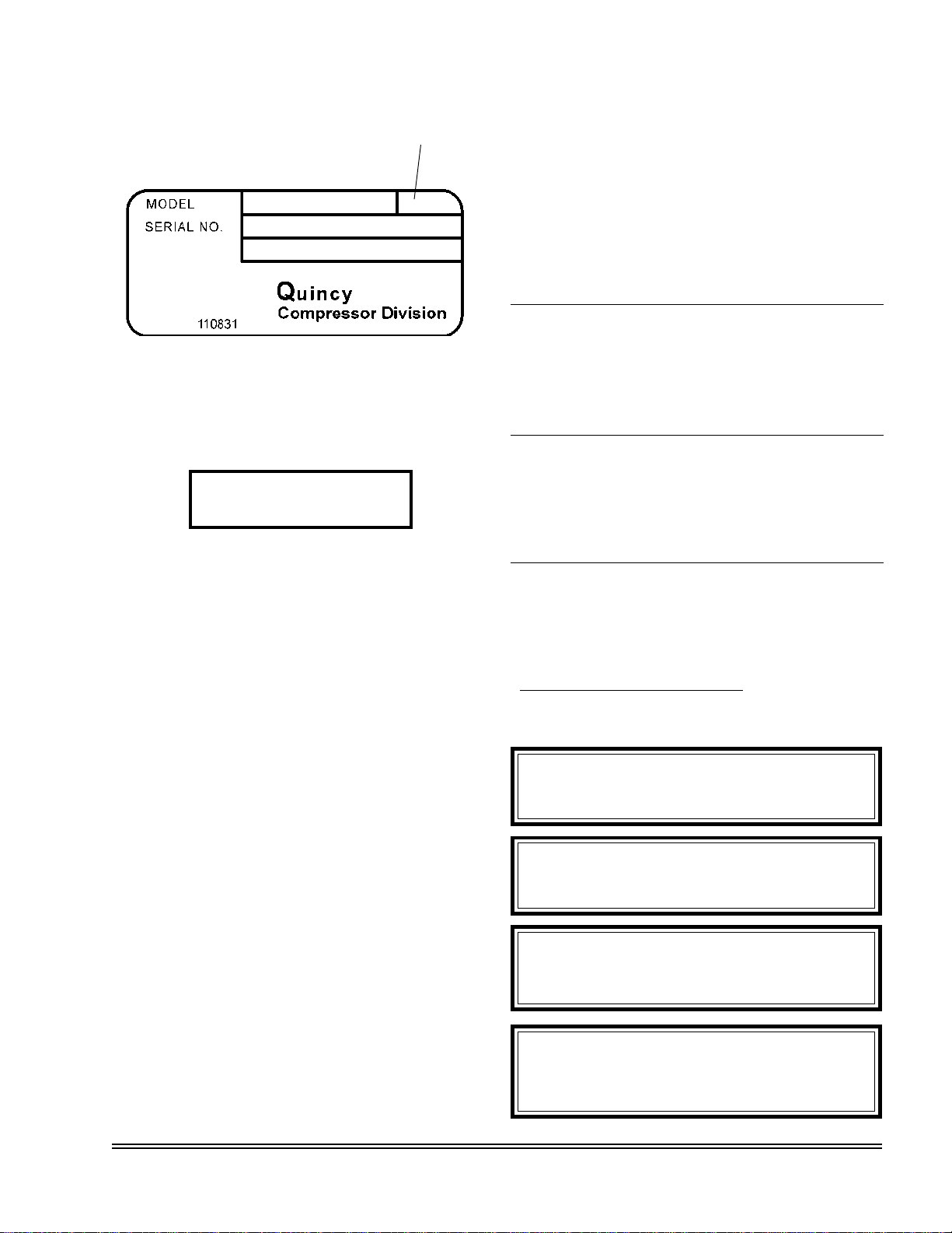
Model & Serial Number
Identification Tag
The model & unit serial number identification tag is
located on the air tank top plate.
Record
of
Change No.
Serial Number
___________
The basic compressor serial number decal is located
on the cylinder flange. Fill in the numbers from your
compressor unit and basic compressor in the corre-
sponding spaces provided here, and reference this
page when ordering replacement parts.
All replacement parts are to be ordered through an
authorized Quincy Compressor Distributor. Insist on
genuine Quincy parts only! Failure to do so may void
warranty.
ORDERING
REPLACEMENT PARTS
Prompt service can be rendered on repair parts or-
ders if the following information is given:
Item 1) the model number, record of change num-
ber, & serial number.
Item 2) the exact part number needed. (Do not
order by item numbers.)
Item 3) the exact quantity needed.
Item 4) the preferred type of transportation.
QUIN-CIP OIL
Refer to the chart below to order QUIN- IP compres-
sor oil from your local Authorized Quincy Compressor
Distributor.
DANGER !
Follow all safety precautions outlined in the AirMasterTwo
Stage Series instruction manual.
Do not operate this compressor without a totally enclosed
belt guard or any other required safety equipment.
Air used for breathing or food processing must meet O.S.H.A.
9 0. 34 or F.D.A. 2 C.F.R. 78.3570 regulations. Failure to
do so may cause severe injury or death.
WARNING !
CAUTION !
CRANKCASE LUBRICANT
CAPACITY
Refer to the AirMaster Series instruction manual for vital
lubrication information.
CAUTION !
Model Capacity
QT-7.5 15/8 Qts. (1.5 lit.)