Valhalla Zeus User manual

Zeus
Turntable
Motor Speed
Controller /
Tachometer

1Product Overview ..................................................................................................3
2Installing and connecting the controller.................................................................3
2.1 Safety...............................................................................................................3
2.2 Overview.........................................................................................................4
2.2.1 Connecting the FFC ribbon cables...........................................................4
2.2.2 Basic installation overview –LP12 .........................................................5
2.2.3 Configuration menu and tuning software ................................................6
2.2.4 Configuration menus and parameters - introduction ...............................7
2.2.5 Setup Menu - item entry ..........................................................................7
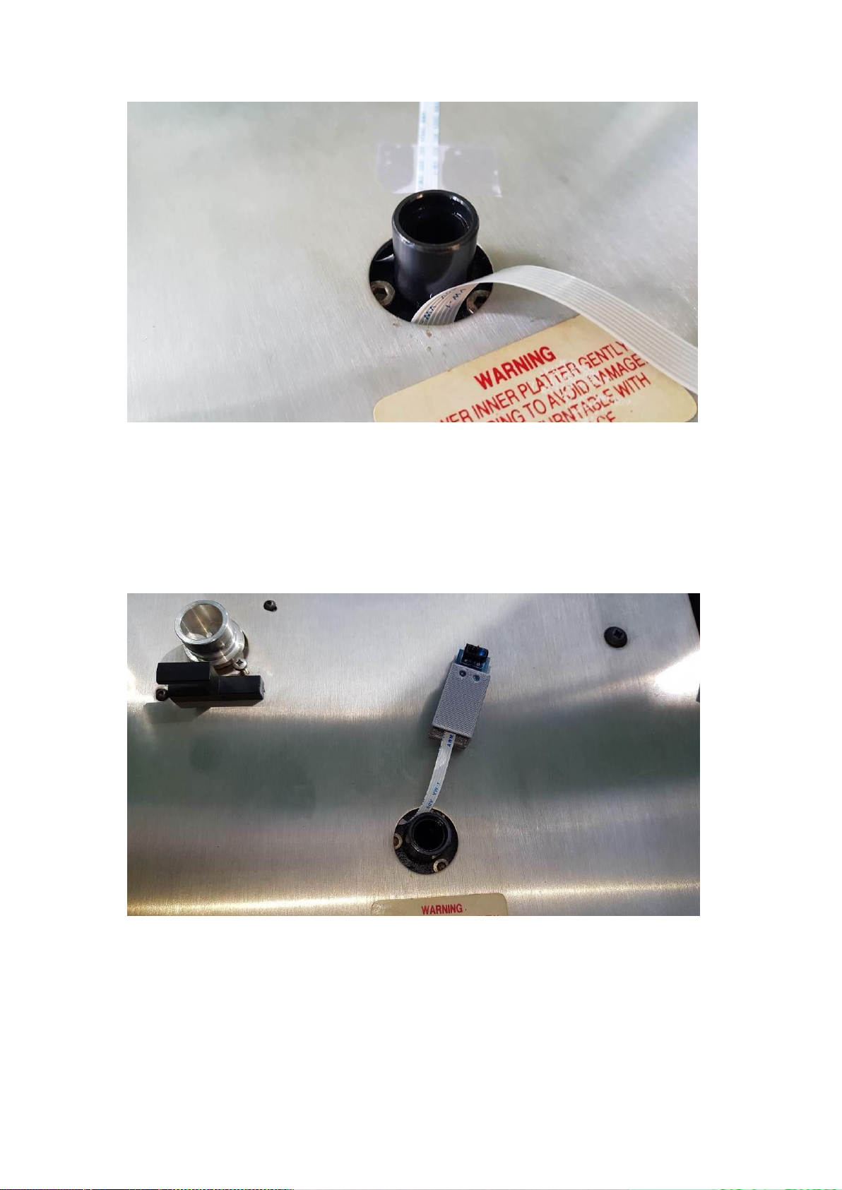
2.3 Mounting the platter internal IR sensor –LP12..............................................7
2.4 Mounting OLED Display –LP12 .................................................................10
2.5 Adaptive Speed Control –PID......................................................................12
2.5.1 Turntable PID values .............................................................................12
2.5.2 Final installation note.............................................................................13
3Configuration menus and parameters ..................................................................14
3.1.1 Setup Menu - item entry ........................................................................14
3.1.2 System Parameters.................................................................................14
3.1.3 Motor Parameters...................................................................................16
3.1.4 PID Control parameters .........................................................................16
3.1.5 Test platter Sensor Trigger.....................................................................17
3.1.6 RequestedvsProgrammed Values...........................................................17
3.1.7 Write to eeprom .....................................................................................17
3.1.8 Motor ON/OFF ......................................................................................17
3.2 PID Tuning - Theory.....................................................................................18
3.3 Step response.................................................................................................19
3.4 Stability in the time domain..........................................................................19
3.4.1 Analysing step response plots................................................................20
3.5 Tutorial –Manually tuning from scratch ......................................................22
4Appendix - MAC Users.......................................................................................26
5Specifications.......................................................................................................28
6Manufacturer Details ...........................................................................................28

1 Product Overview
The Zeus motor controller is a sub assembly intended for incorporation into an audio
HiFi turntable to provide necessary drive signals to the originally installed turntable
24 pole AC 115v synchronous motor. The Zeus provides two independent AC signals
for each phase of the AC synchronous motor. The following parameters may be
adjusted using configuration values defined and stored in the on-board
microprocessor: phase drive voltage, frequency and phase delay. Adjustable values
mean the user may adjust the parameters to achieve minimum motor vibration and
noise in their turntable which is highly desirable.
The microprocessor also incorporates a Proportional, integral and Derivative (PID)
control algorithm. By utilising an optical sensor to read the turntable platter rotation
speed and using the PID algorithm adjustment of the AC signals fed to the motor is
possible. The feedback loop created by the sensor and PID result in accurate speed
control and low WOW values and compensate for turntable wear and tear, also stylus
drag.
2 Installing and connecting the controller
2.1 Safety
WARNING: The Zeus motor controller MUST be installed inside a
turntable plinth that does not allow any physical contact with the Zeus
printed circuit board. Hazardous voltages exist on the printed circuit
board that may result in injury or death. If in doubt consult your dealer
who will be happy to install the controller board for you.
WARNING: Only ever connect a Laptop/PC USB connection via USB
cable routed out of your turntable plinth –do not operate the board
with the plinth baseboard removed as hazardous voltages exist within
the Zeus board.
INFORMATION: It is usual for the heatsinks to get hot during normal
operation typically 70-80 degrees centigrade.

2.2 Overview
The Zeus board may be mounted inside the LP12 turntable on a Linn (or compatible)
cross brace. The minimum connections are mains power and motor wiring. It’s
possible to operate the board with just these two connections, however, most users
will want the start/33/45/stop switch, the OLED display and IR sensor for adaptive
(PID) speed control.
Figure 1 - Pictorial wiring for a 2 phase synchronous motor
The on/off/speed switch is a standby switch. The board may be configured to go into a
low power sleep state after a period of inactivity.
The procedure for installation is in two parts. Basic installation and adaptive PID
speed control.
2.2.1 Connecting the FFC ribbon cables
Slide the black retaining clip forward about 1.5mm away from the connector –this
will release the latch. When connecting the cable back the contacts face towards the
PCB. Slide the blue tab in and push the black retaining latch back so it clicks into
place. This will lock the FFC cable in place. When inserting the FFC cables the
contacts on the FFC cables always face the PCB.

2.2.2 Basic installation overview –LP12
1. Remove the turntable power cord from the mains supply, inner & outer platter,
arm counterweight and secure your tonearm with its retaining clip or use
masking tape to secure. To prevent oil leaking out the baring, ensure you tape
over the top of bearing or use a bung
2. Remove the platter base board.
3. Mount the Linn internal cross-brace using plastic stand-off clips. The Linn
bearing should be central in the large circular cut out on the Zeus PCB.
4. Connect the motor to the controller board using the Motor connector block.
The board has legends that should match RED, BLUE and GREY standard
motor colours. If your platter runs backwards the colour coding on your motor
does not match the Linn/Airpax standard so reverse the BLUE & RED wires.
5. If using the original Linn Valhalla switch and flexible cable attach to the black
connector marked LINN-PSW1 with the copper contacts uppermost. If using
the supplied switch remove the existing square LINN switch and replace with
the square switch/PCB assembly. You will need to angle the switch into the
hole –it will be a snug fit. Connect the FFC cable to PSW1 (underneath the
black LINN-PSW1 connector) with the contacts facing towards the PCB.
6. Connect the mains supply cord to the Zeus to either the 230v or 115v
connections as appropriate for your geography.
7. Connect the supplied USB cable to the board Serial connector and route
outside the plinth using the mains power cable cut-out.
8. If you have purchased the OLED/Speed Sensor, route the cables for these
next. See section 2.3 and 2.4 for detailed instructions. Calibrate the sensor.
9. Replace the platter base board.
10. Connect the turntable to the mains supply.
11. Switch on depress the start switch briefly < 0.5 second. The platter should turn
now at 33.3 rpm. If all is fine test 45 rpm by depressing the switch until the

LED flashes. (Approx. 3 seconds). You can switch back to 33.3 by depressing
the switch until the LED flashes.
12. To go into standby, depress the switch for approx. 1 second.
If the controller works without issues and you have purchased the Speed Sensor move
on to the adaptive speed control (PID) step. This section requires critical placement
and adjustment of the IR sensor which you will do after a brief overview of the
configuration menu and software.
2.2.3 Configuration menu and tuning software
It’s best to get your turntable platter spinning first without using the IR platter sensor
and PID control. The motor controller is pre-configured with a set of defaults that
assume you are using a 110v synchronous 2 phase motor. These defaults should get
you through the basic testing for the board.
To configure the board for basic testing use the PIDTuning application (or a serial
console application set to 9600,N,8,1). Interaction with the controller firmware is via
the serial command input and output area:
A configuration menu should be displayed upon initial connection. Note that in later
steps when PID tuning the menu will not display, however, you can always get the
menu to print by inputting the “M” character (not case sensitive) in the Serial Cmd:
Input area and pressing Enter/Return (CR). Any values that you input will remain in
place until power is removed unless you use the Write Current Values to EEPROM
option. On controller power up the EEPROM values are read back into the program.
Your Anti-Virus (AV) program may block the PIDTuning.exe program or show a
warning –this is normal as the program is not digitally signed. You may need to
create an exception in your AV software.

The PIDTuning app is only available on Windows. Although this program makes it
easier to tune the board PID parameters a standard serial console application may be
used on other platforms (e.g. Mac/Linux) for board configuration. Mac users may
need to install drivers to interface correctly with the Zeus –consult section 4
2.2.4 A full list of all the menu options and the default values has been
provided in section 3Error! Reference source not found. -
introduction
The PIDTuning app is only available on Windows. Although this program makes it
easier to tune the board PID parameters a standard serial console application may be
used on other platforms (e.g. Mac/Linux) for board configuration. The board is
already pre-configured for LP12 users.
2.2.5 Setup Menu - item entry
When in each of the menu items you will be asked to respond to a question. For
example: “Enter 33.3 rpm frequency, Hz: (45 –65): 50.0”. The question will be
followed by the units, the range of acceptable values in between the brackets (45 -
65), and finally the current value: 50.0. Either provide a new value within the range
specified or press the Return key (CR) to accept the current value. The section
questions will repeat until the Q key is pressed. The Q key can pre pressed at any
time, not just at the end of a section to exit the current setup menu. You must be back
at the main menu to save any settings to the EEPROM.
2.3 Mounting the platter internal IR sensor –LP12
For Linn LP12 turntables (or turntables with a large space under the platter) an
internal platter IR sensor mounting position is available. Route the 4 way FFC
connecting cable through the central bearing hole (or other available access point).
However, ensure there are no sharp edges to damage the insulation of the FFC cable.
Often the bearing bolt heads have sharp edges so endure the FFC cables are routed in
the spaces between the bolt heads.

Position the IR sensor towards the inside edge of the outer platter. Lightly tack down
the FFC cable for the positioning test. Use either double sided sticky tape or a couple
of small balls of blue/white tack to stick down the IR sensor lightly. Connect the other
end of the 4 way FFC cable to connector P3 on the underside of the motor controller
PCB (silver contacts towards the PCB).
Position the IR sensor diodes to the outside of the platter. Use the supplied black label
approx. 10mm in width, and affix to the inside edge of the platter. Mount the IR
sensor close so that the transmitting and receiving diodes can register the passing of
the tape.

WARNING: Do not connect your turntable to the main supply at this
stage.
With the motor controller powered up on Laptop/PC only, use the PIDTuning app and
choose option 4 from the menu. This will display a message on the terminal area each
time the IR sensor is triggered. Hand rotate the platter and adjust the position the
speed box so that, each time the marker passes the trigger message is displayed. (Also
brief flash from the IR sensor registration indicator LED flashes –it may be possible
to see this light by reflection on the plinth top).
The trim pot location is accessed either through the top or underneath (depending on
the IR sensor supplied). Adjustment of the IR Sensor Trim pot may be required with a
small screwdriver.

Finally tape the FFC down so it does not rub against the inner platter and press the IR
sensor firmly into its final place. You can optionally secure the IR sensor more
permanently by using the supplied double sided tape.
Once a reasonably accurate rpm indication is obtained you can move onto setting up
PID control and tuning the parameters.
2.4 Mounting OLED Display –LP12
Route the 8 way FFC connecting cable through the central bearing hole (or other
available access point). However, ensure there are no sharp edges to damage the
insulation of the FFC cable. Often the bearing bolt heads have sharp edges so endure
the FFC cables are routed in the spaces between the bolt heads.
Position the OLED case outside of the outer platter wherever you find it aesthetically
pleasing. Lightly tack down the FFC cable. Use either double sided sticky tape or a
couple of small balls of blue/white tack to stick down the OLED case. Connect the
other end of the 8 way FFC cable to connector P1 on the underside of the motor
controller PCB (silver contacts towards the PCB).


2.5 Adaptive Speed Control –PID
Once you have the controller board installed and providing basic 33.3 or 45 rpm
operation; the IR sensor is installed, adjusted and correctly displaying the platter RPM
to a reasonable degree of accuracy (i.e. around 33 or 45 rpm) then you are ready to
enable PID control.
The advantage of PID control is that it reads the actual platter rotation and
compensates for any wear in your components (and stylus drag). It does this by
calculating speed corrections every 50ms using a PID control algorithm. You should
be able to achieve rotation speed accuracy to at least two decimal places. Typically,
the third decimal place will fluctuate.
To enable PID control connect your Laptop to the USB port and go into 1. System
parameters menu. Step through the configuration until you reach “Are you using PID
and platter sensor” –set to Yes and quit out to the main menu. Consult section 2.5.1
to see if there are specific PID values for Kp, Ki and Kd for your turntable. If there
are, use option 3 Set PID control variables and step through the questions setting
values for Kp, Ki and Kd. Quit out to main menu and write the changes to EEPROM
using option 6.
You may find the turntable takes a little longer to reach initial speed (around 8-12
seconds) but when running the accuracy of rotation speed should be far enhanced.
2.5.1 Turntable PID values
If you can find your turntable in the list below you can probably skip the PID Tuning
sections and just enter the values for Kp, Ki and Kd either by using the serial terminal
or the PIDTuning windows application. The boards come supplied with Linn LP12
parameters set. This should get all turntables going with a basic initial set of
parameters. However, you may be able to reduce the time to stable rpm values by
adjusting the parameters below. Please read section 3.2 before attempting to work out
specific PID values for your individual turntable make/model.
Turntable
Model
Motor
Kp
Ki
Kd
Linn
LP12
Linn/Airpax/Philips 2
phase synchronous
0.25
0.25
0.191
Manticore
Mantra
Airpax/Philips 2 phase
synchronous
0.4
0.31
0.191
If you are able to improve on the parameters listed above, please email us with your
turntable details (as per above table) so we can update the table for other users.

2.5.2 Final installation note
Congratulations you have installed the controller. There are many configuration
options and items in the controller that you can tweak and adjust to your specific
turntable. Please feel free to read through section 3 for a full explanation of all of the
parameters. You may find that through experimentation of the motor drive voltages
and slight adjustment of phase angles you can significantly reduce motor vibration
and hence audible noise. Some of the parameters require a re-boot of the controller to
take effect –remember to write to the EEPROM before a re-boot otherwise changes
will be lost. Each time you connect to the controller using the PIDTuning application
or a serial console utility the controller will re-boot.
As a quick start to reducing motor noise start by reducing “Motor full speed voltage
percentage” described in the system parameters section then proceed to adjust motor
phase settings.

3 Configuration menus and parameters
3.1.1 Setup Menu - item entry
When in each of the menu items you will be asked to respond to a question. For
example: “Enter 33.3 rpm frequency, Hz: (45 –65): 50.0”. The question will be
followed by the units, the range of acceptable values in between the brackets (45 -
65), and finally the current value: 50.0. Either provide a new value within the range
specified or press the Return key (CR) to accept the current value. The section
questions will repeat until the Q key is pressed. The Q key can pre pressed at any
time, not just at the end of a section to exit the current setup menu.
3.1.2 System Parameters
Configuration items in this menu relate to general behaviour of the overall controller.
If you live in the UK and are using a 110v synchronous motor, then the default values
should work fine. Worldwide users may need to set the 33.3 & 45 rpm frequencies:
Parameter / Description
Units
Range
Default
value
Enter 33.3 rpm frequency, Hz:
The frequency that needs to be supplied to the
motor to achieve 33.3 rpm rotation
Hz
30-65
50
Enter 45 rpm frequency, Hz:
The frequency that needs to be supplied to the
motor to achieve 33.3 rpm rotation
Hz
65-90
67.5
Soft start frequency delta, Hz:
The difference from the 33.3 rpm starting
frequency when first powered on.
Hz
0-30
10
How many phases on motor:
The number of windings on the motor you are
controlling. Most synchronous motors are 2
phase. Three and four phase motors require an
additional expansion board that contains
additional DDS generators and motor amplifiers.
#
1-4
2
Motor full speed voltage, %:
When the motor is running at full speed (WOW
<=0.02%) the voltage drive can be reduced in
order to reduce motor vibration. This parameter
will reduce the drive from 100% to the specified
value. Keep at 100% if feature is not used. You
must have a platter sensor for this function to
work.
%
50-100
100
Power standby sleep time, min:
If the motor drive is idle (not spinning) for longer
than the specified period, the board switches to
low power/sleep mode. It is woken by pressing
Min
1-360
60

the power switch.
Display blank time, min:
Time for the display to blank after starting or
changing speed. 0 disables feature.
Min
0-360
0
Are you using PID and platter sensor?
Have you mounted an IR speed sensor and
connected it to the board. This switches on PID
control. If set to N then the speed of the platter
will still be displayed but adaptive motor speed
control will not be available. We suggest enabling
this after you have the basic non adaptive control
working first.
Y / N
N
Is platter sensor active low?
This means the sensor will output 5v (high) until
the white platter marker or magnet is encountered
when it will output 0V. When using a black label
on a reflective surface this should be set to ‘N’ –
change to ‘Y’ for a white label.
Y / N
N
Automatically start platter on application of
power?
The board can automatically start the platter on
the application of power rather than having to
press a start switch.
Y / N
N
Crystal trim value:
Allows fine trimming of the Arduino crystal
frequency if it is not exactly 16MHz. This is the
master clock so it’s essential that this is set
correctly to achieve exact platter rotation speed.
** You will find a white panel on the PCB which
specifies the correct value to enter here and it
should be set from manufacturing.
#
0 to
18000
**
Display WOW percentage?
This is the % the current rpm is away from the
target rpm
Y / N
N
Enable Frequency Up/Down button on A6
Allows a manual up/down push buttons to be
added to set the frequency. Consult Appendix
Error! Reference source not found. for wiring
Y / N
N
Display set frequency on line 2 of OLED?
Set Frequency will display in place of WOW
indication (If WOW indication set to N)
Y / N
N

3.1.3 Motor Parameters
Configuration items in this menu relate to the motor and turntable.
Parameter / Description
Units
Range
Default
value
Winding 1 phase is always starts at 0 degrees.
This is a statement. Subsequent windings
probably require 90, 180, 270 degree phase angles
respectively depending if you are using 2,3,4
phase motors.
-
-
-
Enter winding %d, phase angle in deg
Windings probably require 90, 180, 270-degree
phase angles respectively depending if you are
using 2,3,4 phase motors.
Slight adjustment of phase angles can reduce
motor vibration. Start with the defaults and adjust
on test. If you can hold the motor in your hand
this is the best way to determine vibration.
Listening to the motor noise is also a good
indication.
degrees
45 –
300
90, 180, 270
for each
phase 2, 3, 4
respectively
Enter winding n, drive voltage (rms)
The voltage that should be applied to each
winding. For 110v synchronous motors 85v rms is
a good starting point. Slight adjustment of phase
voltages can reduce motor vibration. Start with
the defaults and adjust on test. If you can hold the
motor in your hand this is the best way to
determine vibration. Listening to the motor noise
is also a good indication. However, if you set to
low a voltage then the platter will fail to turn or
not make it up to 45 rpm.
Volts
(rms)
5-100
85
3.1.4 PID Control parameters
Proportional, Integral, Derivative control is an adaptive speed control algorithm. It
uses the IR platter rotation sensor to adjust the frequency fed to the motor to help
maintain an accurate 33.3 or 45 rpm rotation speed. Further details on setting the
values are provided in a separate section. We recommend initial testing is done only
with motor drive and IR sensor to get the system initially working. Once you get an
rpm indication in the region of 33 or 45 rpm from the IR sensor, only then proceed to
configure PID. To get to the parameters in this setup section you must answer Y to
“Are you using PID and platter sensor?” in the system parameters section.

Parameter / Description
Units
Range
Default
value
Enter Kp:
Value for proportional term (up to 6 decimal
places)
#
0-5
0.4
Enter Ki:
Value for term (up to 6 decimal places)
#
0-5
0.31
Enter Kd:
Value for derivative term (up to 6 decimal places)
#
0-5
0.191
Enter Motor frequency to rotation ratio:
(to7 decimal places). As the PID controller works
on frequency it is necessary to convert the rpm
value into an equivalent frequency. This will be
dependent on the type of motor used and the
pulley size. However, it may be simplified to the
ratio of the frequency to platter rotation speed at
33.3 rpm. Use the formula to work out the ratio:
33.333/Motor frequency (to obtain 33.333 rpm).
For UK: 33.333/50 = 0.66666. For US 33.333/60
= 0.55555
#
0-1
0.66666
Debug PID to Serial Monitor?
Displays setpoint, output, feedback values to the
serial console. When adjusting the PID values
using the PIDTuning app this parameter will be
set to Y automatically to enable the tuning graph
to work. The rpm indication on the serial monitor
will be temporarily disabled.
Y / N
N
3.1.5 Test platter Sensor Trigger
This menu option turns enables/disables an on screen message each time the RPM
sensor is triggered. Primarily used during sensor placement.
3.1.6 RequestedvsProgrammed Values
This is an internal debugging menu which will convert requested frequency values
into the closest values the DDS generator can produce
3.1.7 Write to eeprom
Use this option to save configuration parameters to the internal EEPROM so they are
used when the board is powered up,
3.1.8 Motor ON/OFF
Turns the platter on or off instead of the manual power switch,

3.2 PID Tuning - Theory
The following explanation of PID theory will help you to understand the control
system and common terms that are used.
Proportional Gain (Kp)—Proportional gain is the system stiffness. It determines the
contribution of restoring force directly proportional to the position error. Restoring
force is comparable to a spring in a mechanical system.
A high proportional gain gives a stiff responsive system but can cause instability from
overshooting and oscillation.
Derivative Gain (Kd)—Derivative gain is the damping effects on the system. It
determines the contribution of restoring force proportional to the rate of change
(derivative) of position error. This force is much like viscous damping in a damped
spring and mass mechanical system—a shock absorber, for example.
Increasing derivative gain reduces oscillation at the commanded position, or it rings
because of high acceleration.
Integral Gain (Ki)—Integral gain is the static torque load on the system. It determines
the contribution of restoring force that increases with time, ensuring that the static
position error in the servo loop is forced to 0. This restoring force works against
constant torque loads to help achieve zero position error when an axis is stopped.
Integral gain improves positional accuracy. High static torque loads need integral
gains to minimize position error when stopped.

3.3 Step response
We will use a step response to determine values for Kp, Ki and Kd. This will be in the
form of starting the turntable from 0 rpm to 33.3 rpm or 33.3 rpm to 45 rpm. The
system is the combination of the Zeus motor controller, your motor, belt, pulley and
platter. To view your system’s step response, use the PIDTuning application, connect
the serial port and click the Start button. Use this graph panel will plot the transient
response of your system. Typically, the transient response is measured by first
commanding a step, then measuring how quickly a system takes to reach a steady
state. Using the transient response, you can calculate the maximum overshoot, rise
time, peak time, and settling time of your system.
3.4 Stability in the time domain
Use Step Response to determine the relative stability of the system. A system is
considered stable if the actual value is finite when the commanded value is finite. In
other words, a system is stable if a commanded position results in the motor coming
to the desired speed.
A system is considered unstable when any commanded value typically results in an
exponential increase in rotational speed error. In other words, a system is unstable
when its attempts to achieve a set value that results in oscillations that never dampen.
The following graphs are for illustration of general PID tuning theory –they are not
from the PIDTuning application. The PIDTuning application will produce similar
results but the graphs will not be quite as smooth.
The following figure, illustrates a Step Response and shows a typical step response
for a motor. Following the chart is a description of elements to consider when
determining the stability of a PID control system.

Settling Time—the time required by the response curve to reach and stay within a
range that is approximately the final value of size specified by the absolute percentage
of the final value (2% to 5%).
Rise Time—the time required by the response to rise from 10% to 90% of its final
value; the faster the response time of the system, the faster the rise time.
Peak Time—the time required for a response to reach the first peak of the overshoot.
Maximum Overshoot—the maximum peak value of the response curve measured
from the desired position. The maximum overshoot directly indicates the relative
stability of the system.
Commanded Position—the desired position (or rotation speed). In this case, the
commanded value is 1,000. For the Zeus motor controller this will be the value in Hz
for 33.33 rpm or 45 rpm.
Steady-State Position Error—the error that occurs when the system is at rest.
Settling Band—the area the position must be within in order to determine settling
time.
3.4.1 Analysing step response plots
This section provides definitions and sample diagrams of the six most common
response types.
An unstable system, shown below, produces an oscillatory, exponentially diverging
step response. This kind of system never settles down; in fact, the oscillations tend to
worsen over time.
Table of contents