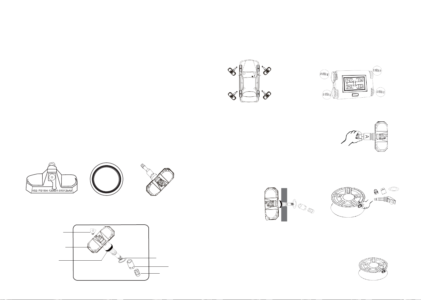
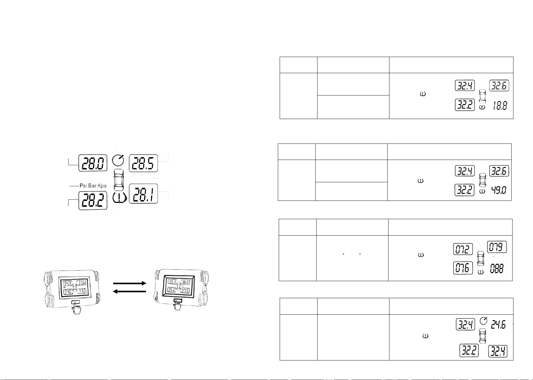
1.4 Start-up Screens
After you turn on the unit, you will see start-up screens as follows.
Screen test Model & Version Normal Pressure Screen
PART TWO System Installation
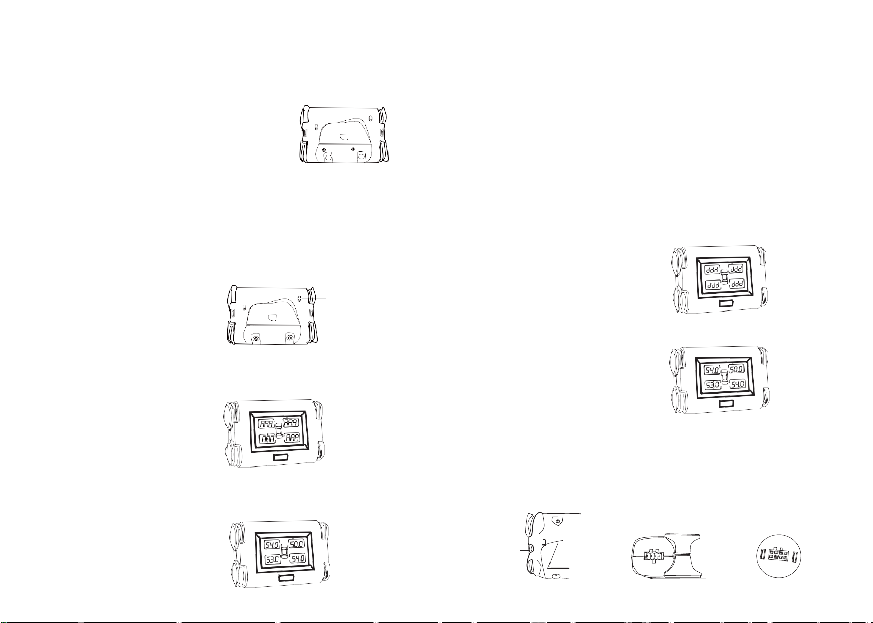
2.1 Mounting of Display
Fix the display unit on the dashboard with double-sided tape. Do not block the driver's view. Pay attention
to the viewing angle of the display.
2.3 Mounting of Power Cord
Option 1: Connect the power cord with permanent battery
We recommend option 1. In this option, display is electrified and shows
the data collecting from transmitters even the car is stopped.
1. Connect the power cable with main harness with fuse.
2 .Remove the cover on the side of the dashboard or below the dashboard.
3. Now, if correctly connecting the red wire and the blue wire with the
positive pole and cathode in the circuit board of the car respectively, the
screen backlight will light up in white and display “000” at the four corners
in the display. If the display doesn’t light up, make sure the connection is
right or the switch on the back of display is on.
We recommend to install display on the dashboard near the “A” post but not next to “A” post, or in the
middle of dashboard for better signal receiving.
2.2 Mounting of Dual Long Antenna
1.
Place the cable of the antennas underneath rubber layer along the front edge of the dashboard.
2.
Place the two antennas underneath the rubber layers of two ‘A’ posts.
4. The joint should be safely wrapped with friction tape. Tie up all the cables with a strap and put in the
compartment. Then replace the dashboard cover.
Option 2: Plug adapter into cigarette lighter
1.
Connect the lighter adapter with main harness with fuse.
2.
Plug the head of lighter adapter into the cigarette lighter socket.
3.
Switch on the power of vehicle (unnecessary to ignite the vehicle), the
screen backlight will light up in white and display “000” at the four corners
in the display. If the display doesn’t light up, make sure the connection is
right or the switch on the back of display is on.