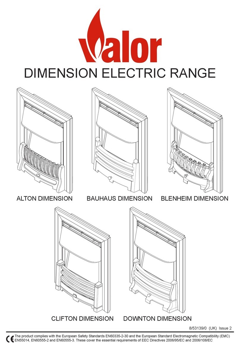
Valor 495 Assembly instructions
Other Valor Indoor Fireplace manuals
Valor
Valor LEGEND G4 780JN (NG) Installation instructions
Valor
Valor LEGEND G3.5 User manual
Valor
Valor Valorstar VN12-N User manual
Valor
Valor 738BVN Installation instructions
Valor
Valor OXYSAFE CONTOUR 3290 User manual

Valor
Valor 1500IN Operating instructions

Valor
Valor 941 Instructions for use
Valor
Valor AutoFire G3.5 User manual
Valor
Valor Horizon 673EDN User manual

Valor
Valor Ultimate Assembly instructions

Valor
Valor C1 Assembly instructions
Valor
Valor 517 User manual

Valor
Valor Black Beauty Unigas II Assembly instructions
Valor
Valor H5 1100MN Planning guide

Valor
Valor Sunfire 337 User manual

Valor
Valor CHURCHILL 32-810-58 Assembly instructions

Valor
Valor 785ILN User manual
Valor
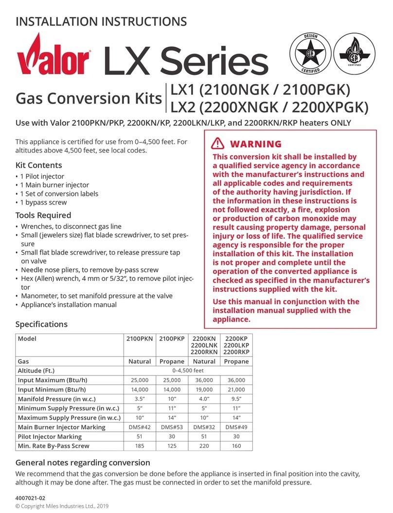
Valor LX Series User manual
Valor
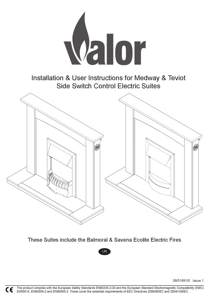
Valor medway User manual
Valor
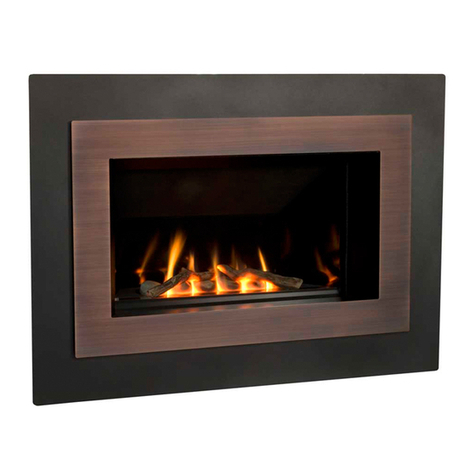
Valor 650ILN Manual
Popular Indoor Fireplace manuals by other brands

Brigantia
Brigantia 35-DVRS31N-2 User's installation, operation and maintenance manual

Nordpeis
Nordpeis Bergen Installation and user manual

Superior
Superior BCT2536TMN Installation and operation instructions

Quadra-Fire
Quadra-Fire 5100I-GD-B owner's manual

Renaissance
Renaissance RUMFORD 1000 user manual

Lacunza
Lacunza IV-800 Instruction book

Baxi
Baxi 940 Installer and owner guide

Dru
Dru Maestro 60/2 Tall RCH installation manual

Diamond Fireglass
Diamond Fireglass SS-O22 General assembly, installation, and operation instructions

HearthStone
HearthStone Windsor Bay 8830 Owner's manual and installation guide

Napoleon
Napoleon ASCENT B42 quick start guide

Enviro
Enviro E33GI owner's manual

Smeg
Smeg L30 FABE Installation & user's instructions

KEDDY
KEDDY K700 Installation instructions care and firing instructions

Godin
Godin 3451 manual

Jøtul
Jøtul Jotul GI 535 DV IPI New Harbor Installation and operation instructions

Desa
Desa CCFPDFT Owner's operating & installation manual

Miles Industries
Miles Industries Vogue 1300IRN Installation & operating instructions

