ValueJet MUTOH VJ-1938TX User guide

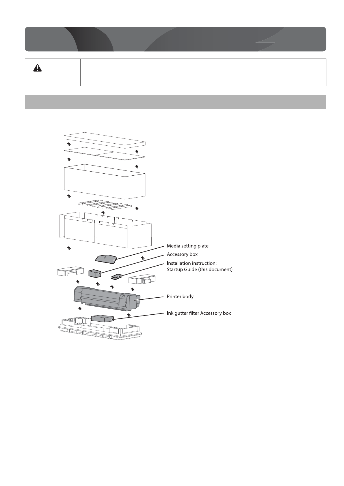
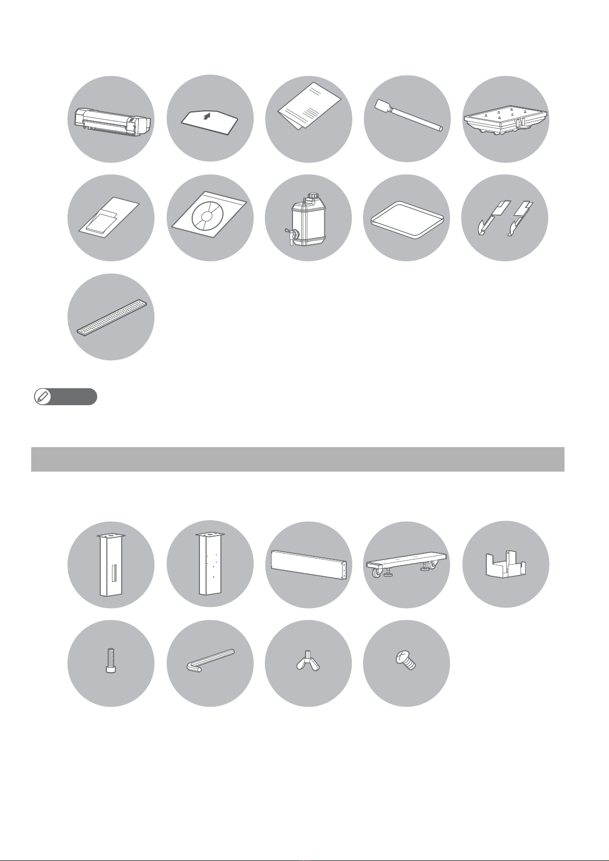
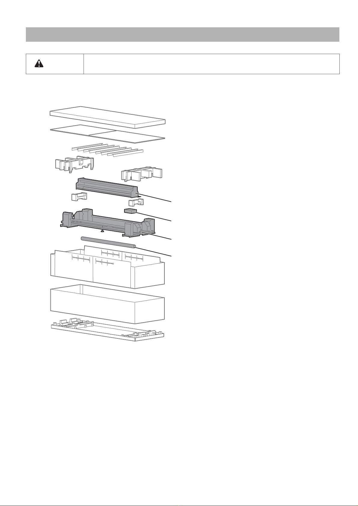
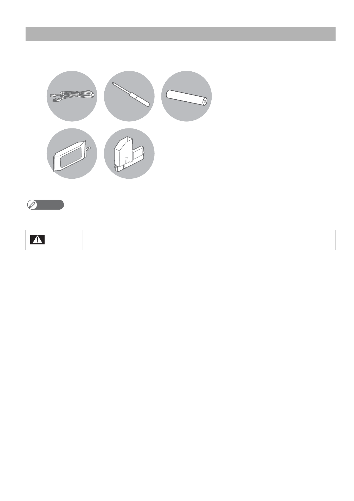
Unpacking . . . . . . . . . . . . . . . . . . . . . . . . . . . . . . . . . . . . 2
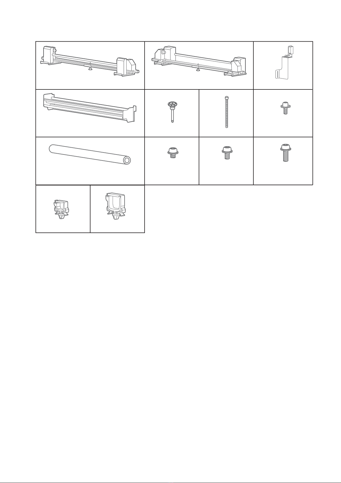
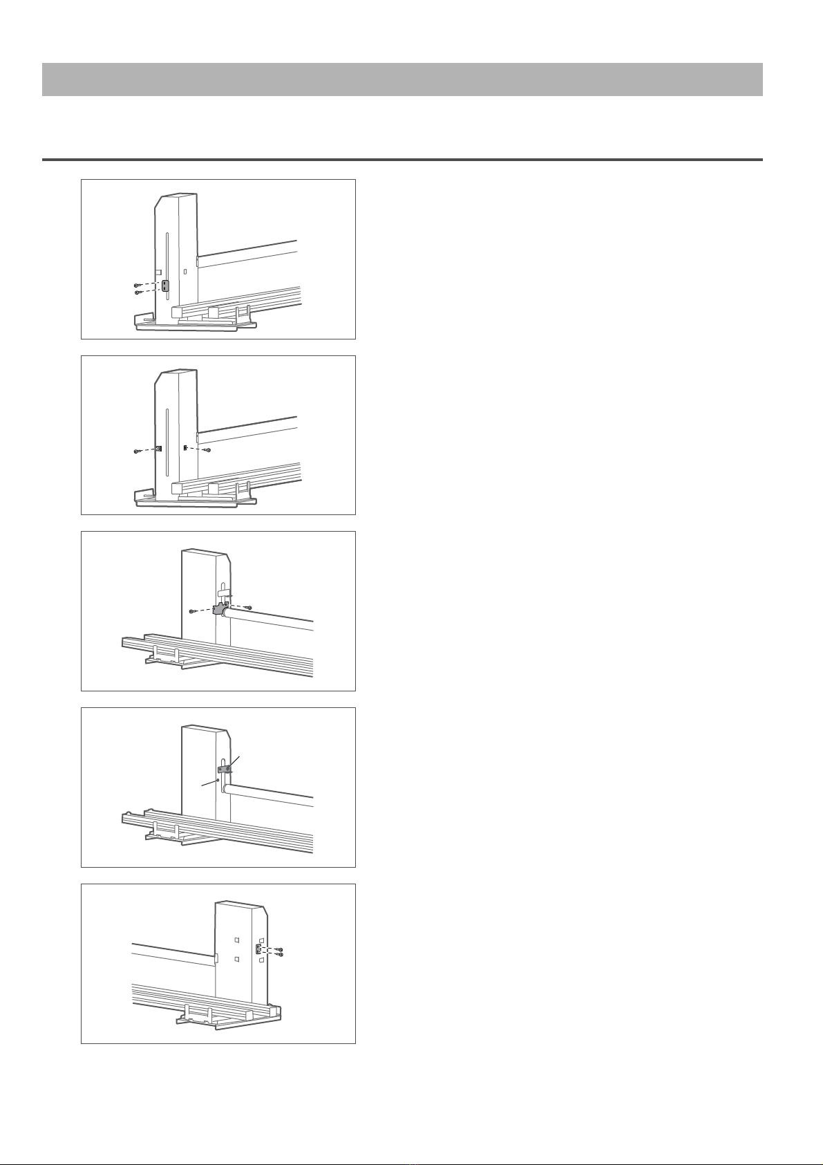
Assembling . . . . . . . . . . . . . . . . . . . . . . . . . . . . . . . . . . 10
Connecting the cables . . . . . . . . . . . . . . . . . . . . . . . . 26
Powering ON / OFF. . . . . . . . . . . . . . . . . . . . . . . . . . . . 28
Setup . . . . . . . . . . . . . . . . . . . . . . . . . . . . . . . . . . . . . . . . 30
Test printing . . . . . . . . . . . . . . . . . . . . . . . . . . . . . . . . . 35
Accessing the Manuals . . . . . . . . . . . . . . . . . . . . . . . . 47
Safety Instructions. . . . . . . . . . . . . . . . . . . . . . . . . . . . 48
• Unauthorized copying or duplication of the whole or part of the contents of this Guide is prohibited.
• Every care has been taken in writing the contents of this Guide, but please contact MUTOH or the dealer you purchased the
product from if you find any unclear, erroneous or otherwise unsatisfactory content in the Guide.
• Please be aware that MUTOH will not be liable in any way for failures or accidents that result from handling or operating the
printer according to any procedures other than those set forth in this Guide.
• Company names and product names that appear in this Guide are registered trademarks of the respective companies.
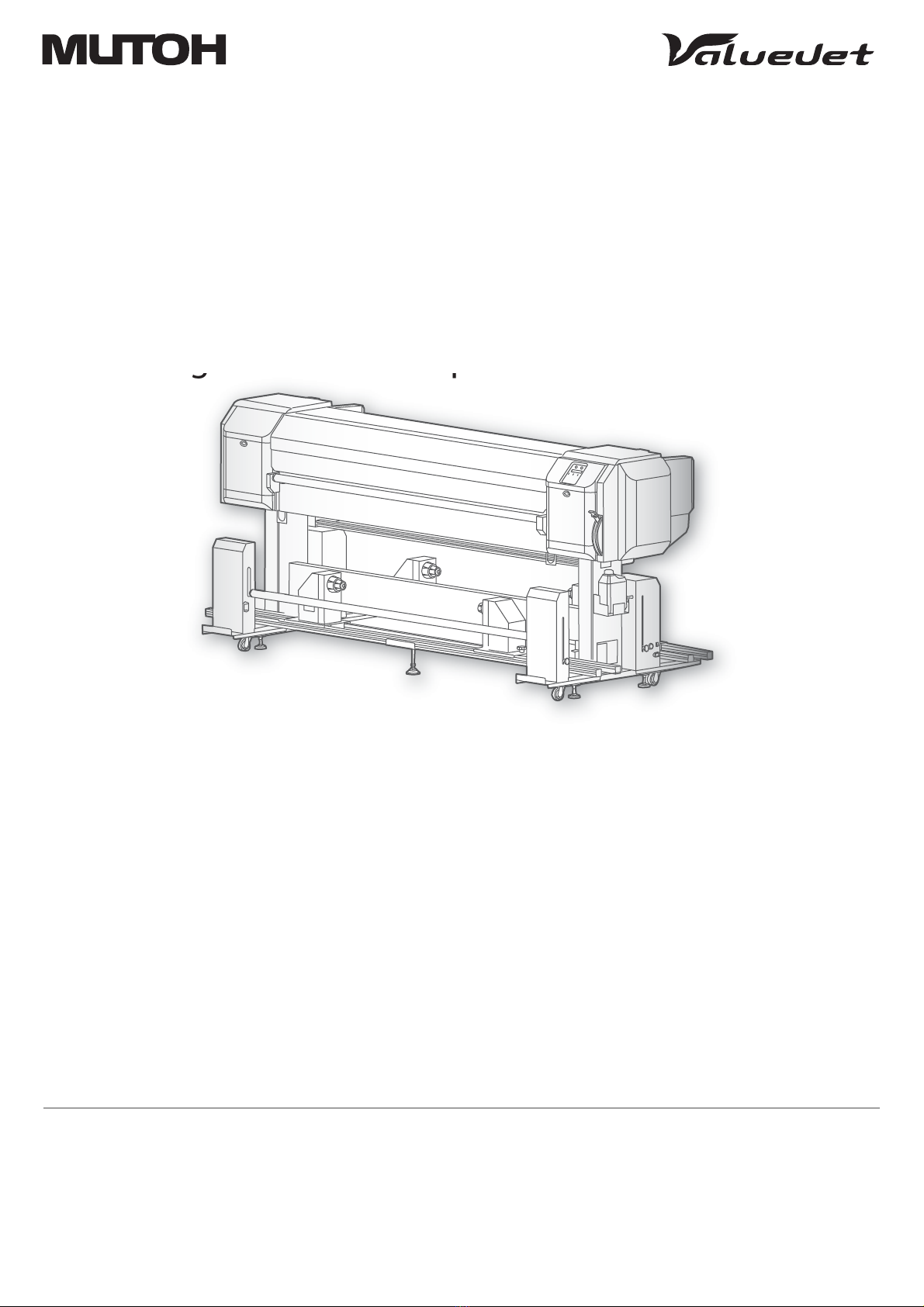
Unpacking and Initial Setup
Startup Guide
VJ-1938TX
gp

2 Unpacking
Unpacking
• The operations of unpacking and moving this product must be carried out by four or more persons
working together.
• Keep this product level when moving it.
Unpacking the printer
[1] Open the packing box and take out each part.
Unpacking
CAUTION

Unpacking 3
[2] Check if the followings are included.
Note
Items marked with an asterisk (*) above are in the accessory box.
Items in the stand box
[1] Check if the followings are included.
Printer: 1
Operation Manual CD: 1
Cleaning stick: 10
Installation Instruction:
Japanese/English (each)
Startup Guide
(this document) Flushing box sponge: 5
**
***
Tray: 1
*
Media holder: 2
Media setting plate: 1
*
Paper towel: 5
*
Waste fluid tank: 1
Ink gutter filter: 8
*
Leg part (Right): 1Leg part (Left): 1
Hexagon socket
head cap screw: 8
Connector bar: 1
Hexagonal wrench: 1 Butterfly screw: 8
Waste fluid tank holder
fixing screw: 4
Waste fluid tank
holder: 1
Base part: 2

4 Unpacking
Unpacking the Take-up System
Unpacking or moving the Take-up System must be done by at least two persons.
[1] Open the box and take out all components.
CAUTION
Take-up unit, Feeding unit
Media tube
Accessory box
Rear roller assembly

Unpacking 5
[2] Make sure that you have all necessary components.
Weight fixing pin: 2
Slack detection sensor: 1Take-up Unit: 1
Rail adjusting screw
:
4
Rear roller Assembly: 1
Feeding Unit: 1
Pan-head screw
with spring washer
and flat washer
M4×12 : 16
Pan-head screw
with spring washer
and flat washer
M4×8 : 7
Media tube: 1
Clamp (small): 5 Clamp (large): 7
Pan-head screw
with spring washer
and flat washer
M3×8 : 2
Pan-head screw
with spring washer
and flat washer
M4×6 : 3

6 Unpacking
To install the product and configure the initial settings, you will need the following items in addition to the packaged items.
Required items for installing and using the printer
Note
Items marked with an asterisk (*) above are accessories or supplies.
Be sure to use a power cable of the specified type.
Using any other power cable could result in electric shock or fire.
**
**
Power cable: 2
High-capacity ink
pack adapter: 8
Media: 1
Phillips-head
screwdriver: 1
1,000 ml ink bag: 8
WARNING

Unpacking 7
Removing the protective materials (Take-up System)
Take-up Unit
[1] Remove the two screws (Pan-head screw with spring washer and flat
washer 4 × 8) from the fixed shaft mounting plate and remove it.
[2] Remove one screw each (Pan-head screw with spring washer and flat
washer M4 × 8) from the tension unit weight fixing materials, and then
remove the two tension unit weight fixing materials.
[3] Remove the two screws (Pan-head screw with spring washer and flat
washer M4 × 8) from the tension roller fixing material and remove it.
[4] Unhook the auxiliary media setting plate from B and hook it to A.
[5] Remove the two screws (Pan-head screw with spring washer and flat
washer 4 × 8) from the fixed shaft mounting plate on the opposite side
and remove it.
B
A

8 Unpacking
[6] Remove one screw each (Pan-head screw with spring washer and flat
washer M4 × 8) from the tension unit weight fixing materials on the
opposite side, and then remove the four tension unit weight fixing
materials.
[7] Remove the two screws (Pan-head screw with spring washer and flat
washer M4 × 8) from the tension roller fixing material on the opposite
side, and remove it.
Feeding Unit
[1] Remove the two screws (Pan-head screw with spring washer and flat
washer 4 × 8) from the fixed shaft mounting plate and remove it.
[2] Remove one screw each (Pan-head screw with spring washer and flat
washer M4 × 8) from the tension unit weight fixing materials, and then
remove the four tension unit weight fixing materials.
[3] Remove the two screws (Pan-head screw with spring washer and flat
washer M4 × 8) from the tension roller fixing material and remove it.

Unpacking 9
[4] Remove the two screws (Pan-head screw with spring washer and flat
washer 4 × 8) from the fixed shaft mounting plate on the opposite side
and remove it.
[5] Remove one screw each (Pan-head screw with spring washer and flat
washer M4 × 8) from the tension unit weight fixing materials on the
opposite side, and then remove the two tension unit weight fixing
materials.
[6] Remove the two screws (Pan-head screw with spring washer and flat
washer M4 × 8) from the tension roller fixing material on the opposite
side, and remove it.

10 Assembling
Assembling
Assembling Procedure
• Make sure you have at least four persons when assembling the printer and stand.
• Make sure you have at least two persons when assembling the Take-up System.
Assembling
CAUTION
Assemble the Take-up System
Assemble the Take-up Unit and Feeding Unit.
Place wires.
Assemble the printer and stand
Assemble the printer and stand.
Install the Rear roller Assembly
Install the Take-up Unit
Install the Feeding Unit
Wire
Install the Rear roller Assembly to the back of the printer.
Install the Take-up Unit to the front of the printer.
Install the Feeding Unit to the back of the printer.
Assembling complete!

Assembling 11
Follow the procedure below to assemble the stand.
Assemble the printer
Four or more persons are required to assemble this printer.
Procedure for assembling the stand
[1] Assemble the right stand.
[2] Attach the right leg part to the right base part so that four screw holes
in the base part are at the front.
[3] Tighten two hexagon socket head cap screws using a hexagonal wrench (supplied accessory).
[4] Assemble the left stand in the same way as in Step 2, 3.
[5] Fasten the connector bar to the right stand using two hexagon socket
head cap screws.
• Attach the connector bar with the groove facing the rear as shown in the
illustration.
[6] Fasten the connector bar to the left stand in the same way as in Step 5.
CAUTION
Leg (right)
Base
Hexagon socket head cap
screws
Screw holes
Front
Screw holes
Front
Leg (left)
Base
Hexagon socket head cap
screws
Stand (right)
Connector bar
Hexagon socket
head cap screws the groove surface
Front
Stand (left)
Connector bar
Hexagon socket
head cap screws
Front

12 Assembling
Follow the procedure below to attach the stand to the printer.
[7] Attach the waste fluid tank holder to the right stand using four screws.
[8] Shake the stand to make sure that each part is firmly attached.
Procedure for attaching the stand
[1] Turn the four adjusters as shown below to prevent the stand from
moving.
[2] Insert the two transfer stays into the right and left transfer brackets, lift
the printer with four or more persons and place it on the stand.
[3] Remove the two transfer stays and fasten the printer to the stand
using eight butterfly screws.
• 1: Transfer stays
•2:Stand
• 3: Butterfly screws
Stand (right)
Screws
Waste fluid tank holder
Stand
Adjusters Adjusters
Stand
Transfer stay
Transfer stay Transfer bracket
Transfer bracket
1
12
2
3
3
3
3
3
3

Assembling 13
Follow the procedure below to attach the waste fluid tank.
Procedure for attaching the waste fluid tank
[1] Place the waste fluid tank in the waste fluid tank holder.
[2] Attach the waste fluid tube to the tank.
[3] Insert the waste fluid sensor cable into the connector on the bottom
of the printer.
Waste uid holder
Waste uid tank
Waste uid tube
Waste uid sensor
cable
Connector

14 Assembling
Follow the procedure below to attach the clamp.
Procedure for attaching the clamp (for the cable of the Take-up System) of the printer base
[1] Attach the clamp (large).
[2] Attach the clamp (small).
[3] Attach the clamp (large).

Assembling 15
Follow the procedure below to detach all protective materials.
Detaching fastening materials (Printer)
[1] Remove all tapes from each cover.
[2] Open the left maintenance cover, then place the tray.
[3] Open the front cover, then remove a screw from the carriage fastening
material (metal plate) and remove the fastening material.
[4] Peel off the tape, be careful not to come in contact with T fence, and
remove the Bearer collapse prevention material and Bearer fix.
Important!
Make sure not to damage T fence during operation. If T fence is damaged, it will affect print results.

16 Assembling
Assembling the Take-up System
Two or more persons are required to assemble the Take-up System.
1. Assembling the Take-up Unit
[1] Install the slack detection sensor using two screws (Pan-head screw
with spring washer and flat washer M3 × 8).
[2] Attach the clamp (small).
2. Assembling the Feeding Unit
[1] Attach one clamp (large) at the position of A.
Attach one clamp (small) at the position of B.
Attach one clamp (large) at the position of C.
Attach one clamp (large) at the position of D.
Attach one clamp (large) at the position of E.
[2] Attach the clamp (large).
CAUTION
A
B
C
DE

Assembling 17
[3] Attach two clamps (small).
Installing the Take-up System
1. Install the rear roller assembly
[1] Hold the rear roller assembly as shown in the illustration.
Important!
• Do not hold the rollers. Otherwise they may deform.
• Make sure you have at least two persons when holding the rear roller
assembly.
[2] Hook the rear roller assembly to the back of the printer.
[3] Temporarily fasten the rear roller assembly using seven screws (Pan-
head screw with spring washer and flat washer M4 × 8).
Important!
When temporarily fastening the rear roller assembly, press it toward the
printer.
[4] Firmly tighten the seven screws that you have temporarily fastened.

18 Assembling
2. Installing the Take-up Unit to the Printer
[1] Loosen the screw with a handle on the front roll unit, and then move
the front roll unit to the center of the rail.
• Once the unit is moved, tighten the screw with a handle.
• Move the front roll units on both sides.
[2] Place the Take-up Unit on the stand.
Note
• Place it so that you can see the screw holes of the stand (four on each side, a total of
eight) through the screw holes of the Take-up Unit.
• Do not hold the tension roller (shown by the arrow A).
Place the front roll unit (drive) so that it is on the waste fluid tank side.
[3] Move the stand so that the projection parts of the stand fit the two
holes on the back of the rail part.
[4] Once the projection parts fit the holes, move the stand to check that the parts firmly fit and do not move.
[5] Secure the Take-up Unit to the stand using eight screws (Pan-head
screw with spring washer and flat washer M4 × 12).
A

Assembling 19
[6] Lower the adjuster so that it touches the floor.
3. Installing the Feeding Unit to the Printer
[1] In the same way as the front side, place the Feeding Unit on the back
of the stand.
Place the rear roll unit (drive) so that it is on the waste liquid tank side.
[2] Secure the Feeding Unit to the stand using eight screws (Pan-head
screw with spring washer and flat washer M4 × 12).
[3] Lower the adjuster so that it touches the floor.

20 Assembling
Wire
1. Wiring from the front side to the rear side
[1] Remove the six screws (cap screw M3 × 6) retaining the cover of the
rear tension unit (Home side), and then detach the cover.
[2] Put the take-up sensor cable (label: J9) and take-up switch cable
(label: J2) through the front side to the rear side.
• A: Untie the cable, and then put it through under the rail.
• B: Put the cable through two clamps on the path.
• C: Put the cable through the grommet.
Note
The take-up sensor cable is the cable that is coming out of the front tension unit (Home
side).
• When you want to put the cable through under the rail in the illustration A
above, make sure that it looks like the left illustration.
[3] Connect the take-up sensor cable (label: J9) to the controller board.
• A: Put the cable around the clamp once.
• B: Connect the cable connector to the connector [J9] on the controller
board.
Note
This illustration only shows the cables that need to be connected in this step and others
are omitted. Other illustrations also follow the same rule.
A
B
C
wv
u
B
A
Table of contents
Other ValueJet Printer manuals