Valueline VL PPC 6015 VW 10 User manual

User manual
Valueline industrial PC
Installation and configuration
UM EN VALUELINE IPC
Order No.: 9047058

PHOENIX CONTACT
Please observe the following notes
User group of this manual
The use of products described in this manual is oriented exclusively to:
– Qualified electricians or persons instructed by them, who are familiar with applicable
standards and other regulations regarding electrical engineering and, in particular, the
relevant safety concepts.
– Qualified application programmers and software engineers, who are familiar with the
safety concepts of automation technology and applicable standards.
Explanation of symbols used and signal words
How to contact us
Internet Up-to-date information on Phoenix Contact products and our Terms and Conditions can be
found on the Internet at:
www.phoenixcontact.com
Make sure you always use the latest documentation.
It can be downloaded at:
www.phoenixcontact.net/catalog
Subsidiaries If there are any problems that cannot be solved using the documentation, please contact
your Phoenix Contact subsidiary.
Subsidiary contact information is available at www.phoenixcontact.com.
Published by PHOENIX CONTACT GmbH & Co. KG
Flachsmarktstraße 8
32825 Blomberg
GERMANY
Should you have any suggestions or recommendations for improvement of the contents and
layout of our manuals, please send your comments to:
This is the safety alert symbol. It is used to alert you to potential personal injury
hazards. Obey all safety measures that follow this symbol to avoid possible in-
jury or death.
There are three different categories of personal injury that are indicated with a
signal word.
DANGER This indicates a hazardous situation which, if not avoided, will re-
sult in death or serious injury.
WARNING This indicates a hazardous situation which, if not avoided, could
result in death or serious injury.
CAUTION This indicates a hazardous situation which, if not avoided, could
result in minor or moderate injury.
This symbol together with the signal word NOTE and the accompanying text
alert the reader to a situation which may cause damage or malfunction to the
device, hardware/software, or surrounding property.
This symbol and the accompanying text provide the reader with additional in-
formation or refer to detailed sources of information.

Please observe the following notes
PHOENIX CONTACT
General terms and conditions of use for technical documentation
Phoenix Contact reserves the right to alter, correct, and/or improve the technical documen-
tation and the products described in the technical documentation at its own discretion and
without giving prior notice, insofar as this is reasonable for the user. The same applies to any
technical changes that serve the purpose of technical progress.
The receipt of technical documentation (in particular user documentation) does not consti-
tute any further duty on the part of Phoenix Contact to furnish information on modifications
to products and/or technical documentation. You are responsible to verify the suitability and
intended use of the products in your specific application, in particular with regard to observ-
ing the applicable standards and regulations. All information made available in the technical
data is supplied without any accompanying guarantee, whether expressly mentioned, im-
plied or tacitly assumed.
In general, the provisions of the current standard Terms and Conditions of Phoenix Contact
apply exclusively, in particular as concerns any warranty liability.
This manual, including all illustrations contained herein, is copyright protected. Any
changes to the contents or the publication of extracts of this document is prohibited.
Phoenix Contact reserves the right to register its own intellectual property rights for the
product identifications of Phoenix Contact products that are used here. Registration of such
intellectual property rights by third parties is prohibited.
Other product identifications may be afforded legal protection, even where they may not be
indicated as such.

2637_en_D PHOENIX CONTACT i
Table of contents
1 Overview................................................................................................................................. 1-1
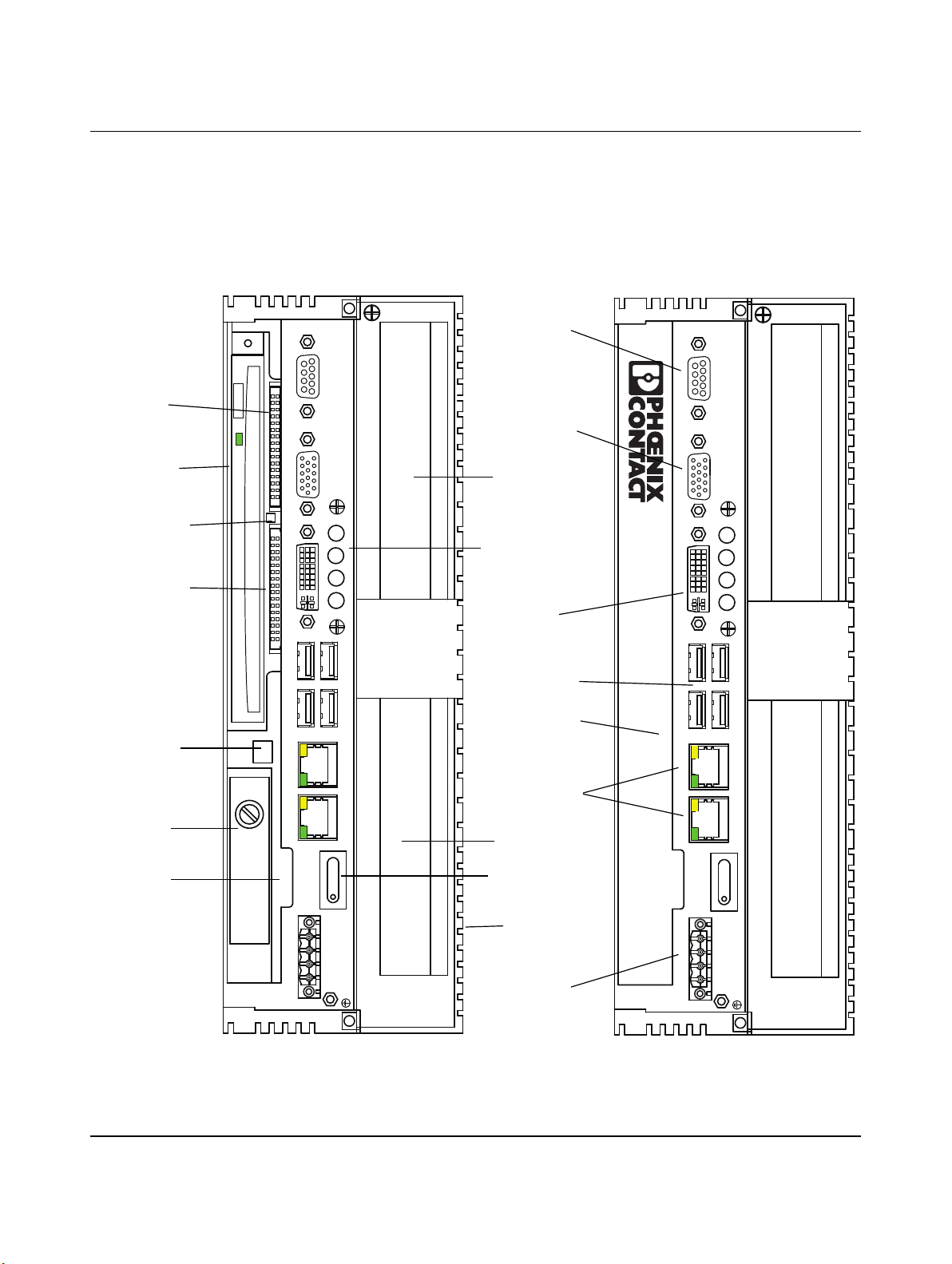
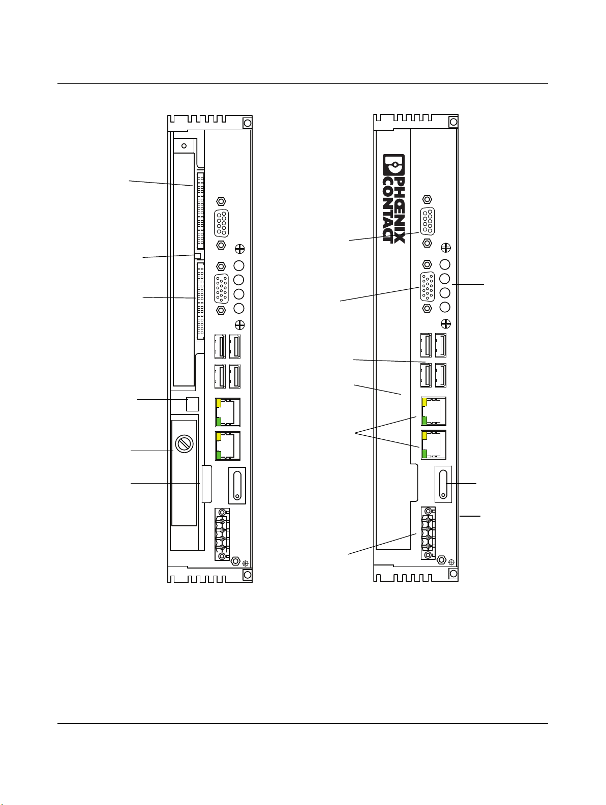
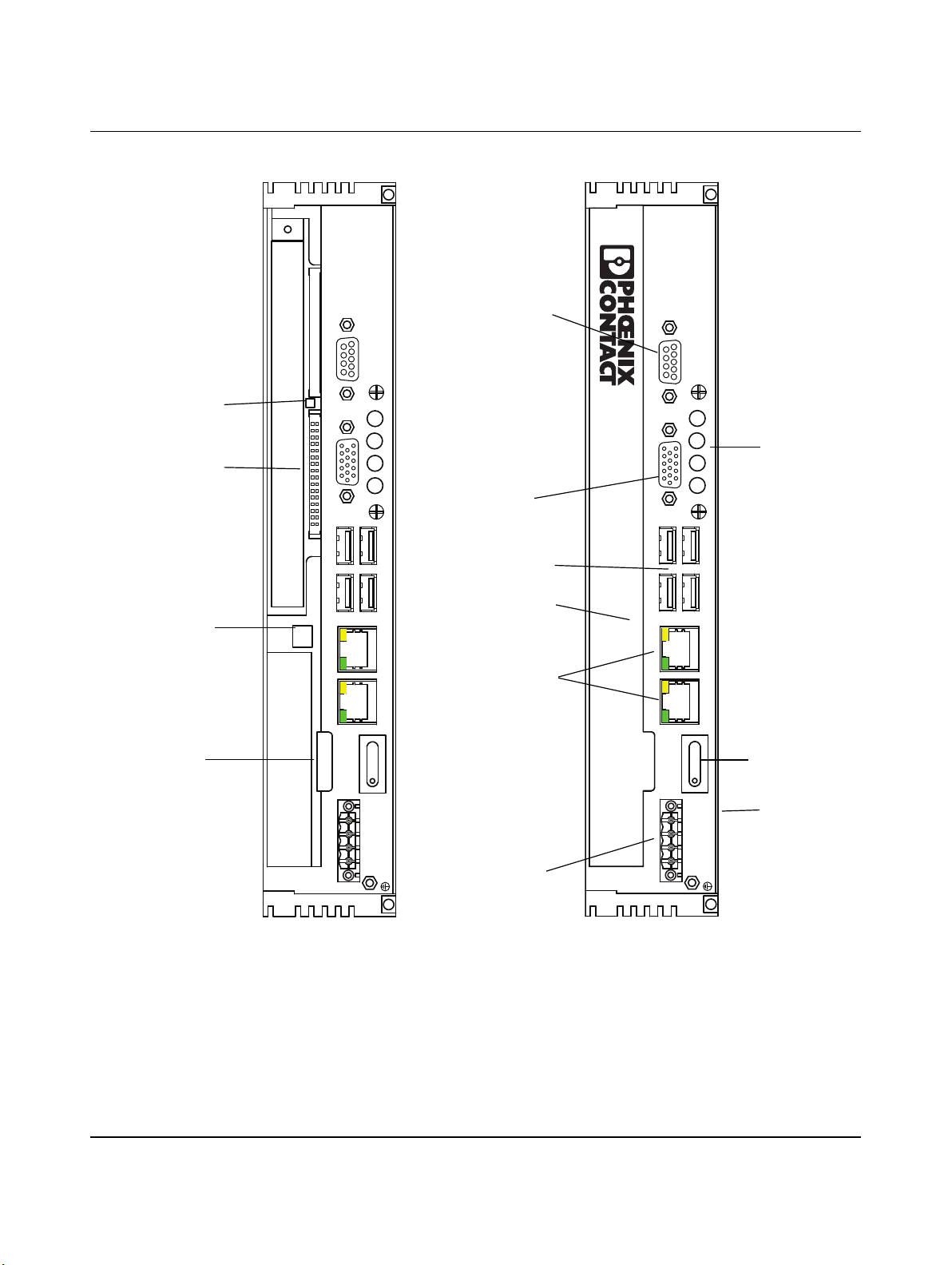
1.1 Getting acquainted with the VL IPC ....................................................................1-2
1.1.1 Status LEDs ........................................................................................1-5
2 Installation............................................................................................................................... 2-1
2.1 Mounting and clearances ...................................................................................2-1
2.1.1 Temperature specifications .................................................................2-1
2.1.2 Wall-mount and bookshelf installation .................................................2-2
2.1.3 Panel mount ........................................................................................2-3
2.2 Interfaces............................................................................................................2-6
2.2.1 Communication interfaces ..................................................................2-7
2.2.2 External display ...................................................................................2-7
2.2.3 Installing PCI cards .............................................................................2-8
3 Startup and Operation ............................................................................................................ 3-1
3.1 Power ................................................................................................................3-1
3.2 Power switch ......................................................................................................3-2
3.3 Software license and activation ..........................................................................3-2
3.4 Firmware and software updates..........................................................................3-3
3.5 Touchkit..............................................................................................................3-3
3.5.1 Touchkit…Setting ...............................................................................3-4
3.5.2 Touchkit… Tools .................................................................................3-7
3.5.3 Touchkit… Edge Compensation .......................................................3-11
3.5.4 Touchkit… Hardware ........................................................................3-13
3.5.5 Touchkit… About ..............................................................................3-14
3.5.6 Touchkit (eGalaxTouch) icon ............................................................3-14
3.6 On-screen Tools...............................................................................................3-15
3.6.1 Brightness Control ............................................................................3-15
3.6.2 Right-Click tool ..................................................................................3-16
3.6.3 On-Screen Keyboard ........................................................................3-17
3.7 Intel®Graphics Media Accelerator user interface.............................................3-18
3.7.1 User interface ....................................................................................3-18
3.7.2 Single Display configuration ..............................................................3-20
3.7.3 Multiple Display configuration ...........................................................3-22
3.7.4 Adjusting 3D operation ......................................................................3-25
3.7.5 Configuring video overlay ..................................................................3-26
3.7.6 Schemes ...........................................................................................3-26
3.7.7 Hot Keys ...........................................................................................3-27
3.7.8 Zoom ................................................................................................3-28
3.7.9 Graphics Information ........................................................................3-29

Valueline IPC
ii PHOENIX CONTACT 2637_en_D
3.8 Uninterruptable power supply...........................................................................3-30
3.8.1 Power supply recommendations .......................................................3-31
3.8.2 QUINT-DC-UPS… installation ..........................................................3-31
3.8.3 TRIO-UPS… installation ...................................................................3-37
3.9 Accessing the optical drive ...............................................................................3-38
3.10 Using CompactFlash cards ..............................................................................3-39
4 Maintenance........................................................................................................................... 4-1
4.1 VL IPC components............................................................................................4-2
4.1.1 Real-time clock battery ........................................................................4-5
4.1.2 Hard disk drive ....................................................................................4-5
4.2 BIOS configuration .............................................................................................4-6
4.2.1 Boot options ........................................................................................4-6
4.2.2 Power on after power fail options ........................................................4-7
4.3 Troubleshooting..................................................................................................4-8
4.3.1 Video driver .........................................................................................4-8
4.3.2 QUINT-DC-UPS… and Valueline IPC (Windows XP) ..........................4-8
4.3.3 Miscellaneous solutions ......................................................................4-9
A Product data ........................................................................................................................... A-1
A 1 Ordering data.................................................................................................... A-1
A 2 Technical data .................................................................................................. A-1
B Appendices............................................................................................................................. B-1
B 1 List of figures .................................................................................................... B-1
B 2 List of tables ..................................................................................................... B-5

Overview
2637_en_D PHOENIX CONTACT 1-1
1 Overview
The Valueline industrial personal computers is a general purpose modular design that can
be manufactured to a wide variety of application requirements. There are three processor
options: Celeron®, Core™2 Duo and Atom™ when ordering a Valueline IPC.
Standard hardware features for all Valueline IPC systems include:
– 24 V DC operation
– Fanless operation
– Uninterruptable power supply interface
– VGA output
– 4 USB ports
– 1 COM port (RS-232, 9-pin D-SUB connector)
– Two integrated 10/100/1000 Ethernet ports with independent MAC addresses
– Power, HDD, Run and Error LEDs
Configuration options include:
– Display size or no display
– RAM memory
– No operating system or a Windows®operating system
– Size and type of mass storage
– Front bezel with or without USB slot
– Mounting options
– NVRAM (non-volatile RAM–only available in some configurations)
Available depending on configuration
– DVI-D video output
– Optical storage
– 2 PCI expansion slots
– 1 or 2 CompactFlash®slots
This manual describes the possible options and features of the Valueline IPC available at
the time of printing. For specific part numbers and components, refer to the configuration
sheet included with the unit to determine the installed options.
In some mounting orientations, the labels with the model number, product serial number,
and the Microsoft®Windows®operating system product key are hidden. Copy the
information from these labels before mounting the VL IPC. It’s a good idea to write this
information on the inside cover of this manual.

Valueline IPC
1-2 PHOENIX CONTACT 2637_en_D
1.1 Getting acquainted with the VL IPC
Depending on configuration options selected, the VL IPC may look different. Also, the
various mounting options provide tremendous flexibility.
Figure 1-1 shows the connector side of the VL IPC including an optional optical storage
device, which installs in the basic system, and the optional PCI slots.
Figure 1-1 Valueline IPC with Core™2 Duo or Celeron® processor and optional PCI
slots
X10 COM1 X9 VGA X8 DVI D
ERROR RUN HDD PWR
X7 USB X5 USB
X4 USBX6 USB X3 ETH X2 ETH
X1: PWR 24VDC
+– AB
4
876
13
2
9
5
PUSH
4
876
13
2
9
5
X10 COM1 X9 VGA X8 DVI D
ERROR RUN HDD PWR
X7 USB X5 USB
X4 USBX6 USB X3 ETH X2 ETH
X1: PWR 24VDC
+– AB
PCI Slot 1
PCI Slot 0
Serial Port
VGA Video
Status LEDs
DVI-D
USB Ports (4)
Ethernet Ports
Power Switch
RTC Battery
Heat Sink
(entire back)
CompactFlash
Slot 0
CompactFlash
Slot 1
Optional
Optical Storage
Device
Removable
Hard Disk
24 V DC
Power Connector
Access Door Open Access Door Closed
Press Here
to open
Access Door
Access Door
Catch
CompactFlash
Slot 1 Eject Button

Overview
2637_en_D PHOENIX CONTACT 1-3
Figure 1-2 VL IPC with Atom processor in Atom enhanced chassis
X9 COM X8 VGA
ERROR RUN HDD PWR
X7 USB X5 USB
X4 USBX6 USB X3 ETH X2 ETH
X1: PWR 24VDC
+– AB
4
87
6
13
2
9
5
ERROR RUN HDD PWR
X7 USB X5 USB
X4 USBX6 USB X3 ETH X2 ETH
X1: PWR 24VDC
+– AB
X9 COM X8 VGA
4
87
6
13
2
9
5
PUSH
Serial Port
Status LEDs
USB Ports (4)
Ethernet Ports
Power Switch
24 V DC
Power Connector
Access Door Closed
Press Here
to open
Access Door
RTC Battery
CompactFlash
Slot 0
CompactFlash
Slot 1
Removable
Hard Disk
Access Door
Catch
CompactFlash
Slot 1 Eject Button
Access Door Open
VGA Video
Heat Sink
(entire back)

Valueline IPC
1-4 PHOENIX CONTACT 2637_en_D
Figure 1-3 VL IPC with Atom processor in Atom standard chassis
ERROR RUN HDD PWR
X7 USB X5 USB
X4 USBX6 USB X3 ETH X2 ETH
X1: PWR 24VDC
+– AB
X9 COM X8 VGA
4
87
6
13
2
9
5
PUSH
Serial Port
Status LEDs
VGA Video
USB Ports (4)
Ethernet Ports
Power Switch
X9 COM X8 VGA
ERROR RUN HDD PWR
X7 USB X5 USB
X4 USBX6 USB X3 ETH X2 ETH
X1: PWR 24VDC
+– AB
4
87
6
13
2
9
5
24 V DC
Power Connector
Access Door Closed
Press here
to open
Access Door
Heat Sink
(entire back)
RTC Battery
CompactFlash
Slot 1
Access Door
Catch
CompactFlash
Slot 1 Eject Button
Access Door Open

Overview
2637_en_D PHOENIX CONTACT 1-5
1.1.1 Status LEDs
There is a set of four LEDs.
Figure 1-4 LED layout
Table 1-1 LED status indicators
LED Indication Description
ERROR Yellow
Red
Indicates reduced performance due to processor
temperature
Indicates an over temperature condition has caused the
processor to shut down
RUN Reserved for future use
HDD Flashes
green
Indicates hard drive activity
PWR Green When 24 V DC is applied and the power switch is turned
On
X8 DVI D
ERROR RUN HDD PWR

Valueline IPC
1-6 PHOENIX CONTACT 2637_en_D

Installation
2637_en_D PHOENIX CONTACT 2-1
2 Installation
The flexibility of the Valueline IPC allows many different installation options.
2.1 Mounting and clearances
Depending on the configuration ordered, there are several ways to mount the VL IPC. Use
the appropriate section below to mount the VL IPC.
When installing the VL IPC in a cabinet, follow these general rules:
– Verify clearances within the cabinet. Typically, leave at least 5 cm (2 in.) on each side
with 12.7 cm (5 in.) on the connector side if the VL IPC has the optional optical storage
drive.
– Drill all holes and make all cuts before beginning installation. Be sure to protect already
installed components from shavings.
– Supporting panels must be at least 14 gauge to provide proper support.
– Make sure that there is adequate space around the heat sink (on the back of the VL IPC)
and air inlets and outlets to provide sufficient cooling.
2.1.1 Temperature specifications
Operational temperature limits depend on the specific configuration of the Valueline IPC
(see Table 2-1 “Temperature limits” for details).
NOTE:
Install the VL IPC with adequate clearance around the heat sink to provide sufficient air
flow such that ambient temperatures do not exceed the operating limits listed in
Section 2.1.1, “Temperature specifications”. Install cooling fan(s) in the enclosure, if
necessary.
Table 2-1 Temperature limits
Configuration Ambient range (operating)
Any processor with no display, 12-, 15- or 17-in.
display, solid state drive or CompactFlash®card
-20°C … 55°C (-4°F … 131°F)
Any processor with no display, 12-, 15- or 17-in.
display and rotating hard drive
5°C … 55°C (41° … 131°F)
Any processor with 19- or 24-in. display, solid
state drive or CompactFlash®card
0°C … 50°C (32° … 122°F)
Any processor with 19- or 24-in. display and
rotating hard drive
5°C … 50°C (41° … 122°F)
Please be aware that adding PCI cards can add heat to the system.

Valueline IPC
2-2 PHOENIX CONTACT 2637_en_D
2.1.2 Wall-mount and bookshelf installation
Wall mounts are valid for VL IPCs that do not include a display. Use this type of mounting to
install the VL IPC on the inside of a cabinet. The VL IPC can be attached to a flat surface in
either a wall mount or bookshelf orientation. Either way, attach the unit using the four key
holes. The mounting surface must be flat and not subject to vibration.
Figure 2-1 Wall and bookshelf mounts
To install a wall mounted VL IPC, follow these steps:
1. Use the VL IPC as a template and mark the locations of the key holes on the mounting
surface.
2. Use the correct anchor type for the mounting surface and securely attach the VL IPC to
the wall. Anchor hardware must be smaller than 6 mm. Ensure the attaching hardware
is in the small section of the key holes.
3. Tighten mounting screws. Be careful not to overtighten the attachment hardware.
NOTE:
Exceeding the system temperature limits can result in performance degradation of any or
all components. It is therefore important that the ambient temperature of the installation
environment is kept within the system temperature limits of your Valueline IPC.
X10 COM1 X9 VGA X8DVI D
ERROR RUN HDD PWR
X7 USB X5 USB
X4 USBX6 USB X3ETH X2ETH
X1:PWR 24VDC
+–AB
X10 COM1 X9 VGA X8DVI D
ERROR RUN HDD PWR
X7 USB X5 USB
X4 USBX6 USB X3ETH X2ETH
X1:PWR 24VDC
+–AB
PUSH
PUSH
50.0 mm
289.0 mm
140.0 mm
280.0 mm
24.0 mm
Without PCI
Slots
With PCI
Slots
(11.4 in.)
(5.5 in.)
(2.0 in.) (0.9 in.)
(11.0 in.)
NOTE:
The unit must be installed with the small end of the key hole oriented up.

Installation
2637_en_D PHOENIX CONTACT 2-3
2.1.3 Panel mount
Panel mounts are the only valid mounting system for VL IPCs with a display. This mounting
system permits installation of the VL IPC in a cabinet so the display panel is visible on the
outside (see Figure 2-2).
Figure 2-2 Panel mount
NOTE:
Connectors and switches must be accessible from the rear. A wall panel thickness of at
least 1.9 mm (14 ga.) is required for correct mounting with IP65 protection
INSPIRING INNOVATIONS
Cabinet wall
VL IPC

Valueline IPC
2-4 PHOENIX CONTACT 2637_en_D
1. Cut a hole in the enclosure according to the dimensions for the selected display.
Figure 2-3 Panel cut-out dimensions for displays
2. From the front, push the VL IPC through the opening. Ensure the gasket is properly
positioned in the groove.
Table 2-2 Cutout dimensions
Display size X (mm) Y (mm)
12 in. 334.0 253.0
15 in. 386.6 285.6
17 in. 424.0 329.5
19 in. 443.0 360.0
24 in. 620.4 352.8
X
Y

Installation
2637_en_D PHOENIX CONTACT 2-5
3. From the rear, place the display clamps, 1, in the slots, 2, on the display and slide the
clamp to the right (see Figure 2-4). Clamps must be used in every slot.
Figure 2-4 Panel mount clamps
4. Tighten the screws with a screwdriver on all clamps, alternating from one side to the
other until the front bezel is secure against the panel. Torque the bolts to 1.2 Nm.
1
2

Valueline IPC
2-6 PHOENIX CONTACT 2637_en_D
2.2 Interfaces
After mounting the VL IPC, make any necessary cable connections. Depending on the
mounting method, connections are made at the rear or bottom of the VL IPC (see
Figure 2-5). If the Valueline computer includes PCI slots, additional connections may be
required to the PCI cards inserted in the PCI slots.
Figure 2-5 Interface connections
4
876
13
2
9
5
X10 COM1 X9 VGA X8 DVI D
ERROR RUN HDD PWR
X7 USB X5 USB
X4 USBX6 USB X3 ETH X2 ETH
X1: PWR 24VDC
+– AB
Serial Port
VGA Video
DVI-D
USB Ports (4)
Ethernet Ports
PCI Slot 1
PCI Slot 0
ERROR RUN HDD PWR
X7 USB X5 USB
X4 USBX6 USB X3 ETH X2 ETH
X1: PWR 24VDC
+– AB
X9 COM X8 VGA
4
87
6
13
2
9
5
PUSH
Core2 Duo and
Celeron Processor
Atom Processor

Installation
2637_en_D PHOENIX CONTACT 2-7
2.2.1 Communication interfaces
Various ports and connections allow the VL IPC to communicate with other devices. The
connections available on the IPC module are
–Ethernet: Two RJ45 connectors are located on the rear of the VL IPC. These allow the
computer to communicate on a 10/100/1000 Base-T Ethernet network.
–Serial: Serial devices connect to the DB-9 RS-232 port.
–USB: USB devices connect using Type A connectors. The VL IPC has four USB ports.
–VGA: This port connects the VL IPC to an external analog display with a corresponding
VGA connector.
–DVI-D: This port connects the VL IPC to an external digital display with a corresponding
DVI-D connector.
2.2.2 External display
External displays can be connected to the VL IPC to function as a desktop extension or as
an auxiliary display. Use the VGA port for analog displays and DVI-D port for digital displays.
(see Figure 2-5).
Extended Display Identification Data (EDID) displays will download its capabilities to the
display driver while non-EDID displays will not. In either case, additional settings can be
applied through the Intel®Graphics Media Accelerator (see “Intel®Graphics Media
Accelerator user interface” on page 3-18).
NOTE:
The VL IPC DVI-D port only passes digital signals; therefore, connecting an analog display
to the DVI-D port and using a VGA to DVI adapter will not work.

Valueline IPC
2-8 PHOENIX CONTACT 2637_en_D
2.2.3 Installing PCI cards
Installing a PCI card in the optional PCI slots is done as follows:
1. Ensure the card does not exceed the maximum dimensions for the intended slot (see
“Computer data” on page A-2).
2. Remove power from the unit.
Figure 2-6 Cover removal
3. Place the unit on a soft cloth on a flat, horizontal surface with the ribbed surface (cover)
up.
4. Remove the four Phillips-head screws, 1, from the cover, 2, and remove the cover.
NOTE:
Use standard ESD precautions when removing or installing PCI cards to avoid damage to
the cards and the VL IPC.
The PCI card option is not available with the Atom standard chassis.
PCI Slot 0
PCI Slot 1
2
3
1
Do not remove the tamper-proof (Torx®) screws, 3.
This manual suits for next models
1
Table of contents
Popular Industrial PC manuals by other brands

B&R
B&R Panel PC 3100 user manual

Allen-Bradley
Allen-Bradley 6181X-NPXPDC installation instructions

IEI Technology
IEI Technology FLEX-BX200-Q370 user manual

MiTWell
MiTWell KUBER-2000-IT Series user manual

DMP Electronics
DMP Electronics EBOX-3310MX-TS4C user guide

Cincoze
Cincoze CV-100/P1201 Series user manual