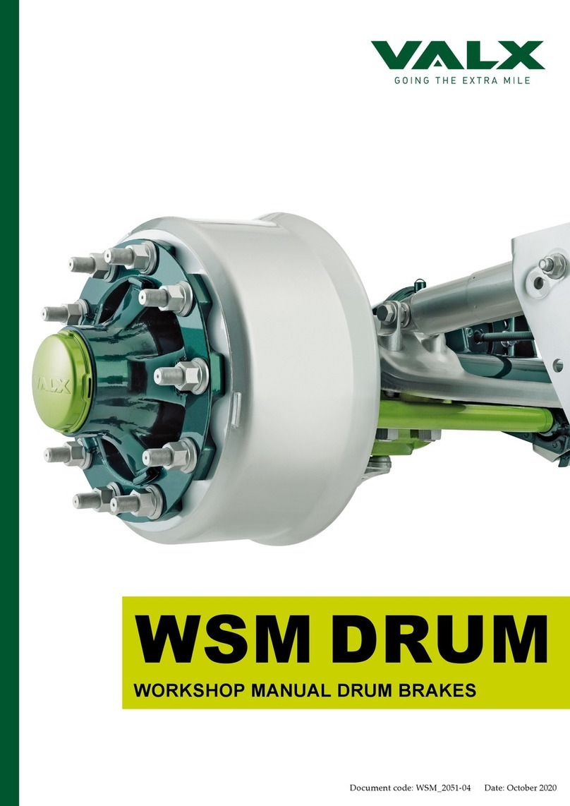
Valx Landing leg S User manual

Document code: M_2080-01_EN Date: February 2020
LANDING GEARS
Installation and operation instructions
Landing leg S and Landing leg H

2 M_2080-01_EN
For additional information on assembly, disassembly, adjustments, maintenance and repair, contact
VALX B.V.:
De Amert 700C, 5462 GH Veghel
The Netherlands
Tel: +31 (0)88-40 58 800 (general)
Tel: +31 (0)88-40 58 899 (breakdown number)
Fax: +31 (0)88-40 58 820
E-mail: [email protected] (general)
www.valx.eu
Document code: M_2080-01_EN
Copyright © 2020
Revision summary
Date Revision number Comment
February 2020 01 Initial version

M_2080-01_EN 3
This document and all information herein is and remains at all times the exclusive property of VALX B.V. and shall not - in
whole nor in part - without the prior wrien permission of VALX B.V. be disclosed to any other person, published in any
form of publicity or news story, copied, photographed, reproduced or stored in any retrieval system of any nature.
The information in this document has been prepared solely for the purpose of providing information about assembly,
disassembly, repair and maintenance on the trailer landing leg. It has been compiled in good faith by VALX B.V. and
is provided without any express or implied warranty as to its completeness or accuracy. We reserve the right to make
amendments to this document to reect further developments.
The original English text in this document will be legally binding and shall prevail in case of any variance between the
English text and a translation. As any translation may be imprecise and inaccurate in whole or in part, VALX B.V. does not
accept any risk, liability and responsibility for any translation.
Any quotations, oers and agreements relating to goods to be delivered and/or services to be provided by VALX B.V. shall
always be subjected to VALX B.V.’s Terms of Sale and Delivery. All other terms and conditions are expressly rejected.
© 2020 VALX B.V. All rights reserved.

4 M_2080-01_EN
Preface
Use of this manual
This Manual is intended for trained and for qualied persons to enable them to perform design, installation and repair
tasks on VALX products in an ecient, safe and environmentally sound way.
TAKE THE TIME TO READ THIS MANUAL THOROUGHLY BEFORE STARTING WORK ON THE TRAILER,
LANDING LEG AND/OR ON OTHER VALX COMPONENTS.
KEEP THIS MANUAL IN A SAFE PLACE, BUT READY TO USE WHEN NEEDED.
THIS MANUAL REPLACES ALL PREVIOUS VERSIONS, IF ANY.

M_2080-01_EN 5
Table of contents
Pictograms in this manual 6
1 General safety instructions and regulations 8
1.1 General 8
1.2 This manual 8
1.3 Decals and instructions on the trailer landing legs 8
1.4 Warranty and original VALX parts 8
1.5 Maintenance and repair 8
1.6 A contribution to the protection of our environment 9
2 Explanation of the landing gears type code 10
2.1 Location of the identication plate 10
2.2 Information on the identication plate 10
2.3 Ordering of parts 10
3. Landing gears complete 12
3.1 Overview 12
4. Installation 13
4.1 Place the wheel chocks 13
4.2 Support trailer 13
4.3 Retract both landing legs 14
4.4 Set minimum ground clearance 14
4.5 Measure and adjust the connection shaft 15
4.7 Mounting and bolting the landing legs 16
4.8 Weld stop blocks (only for H landing legs) 17
5. Operation 18
5.1 Safety instructions 18
5.2 General operations 19
5.3 Un coupling the trailer vehicle 19
5.4 Coupling the trailer vehicle 19
5.5 Loading the supported vehicle 20
6. Maintenance 21
6.1 Periodic maintenance and inspection 21
6.2 Cleaning 21
6.3 Lubricants 22
6.4 Troubleshooting 23
7. Technical data 24
7.1 Landing leg S 24
7.2 Landing leg H 25
8. VALX bv Warranty Commitment 26
9. Repair work time allowances 27

6 M_2080-01_EN
Pictograms in this manual
Pictograms for general alerts
In this manual the following pictograms and symbols may be used for general alerts:
NOTE
Important instruction, recommendation or tip that you must always observe.
If the safety instruction is not observed, a potential hazardous situation can occur, causing personal
injury or damage to the landing leg, the workshop or the environment.
Pictograms for specic alerts
In this manual the following pictograms and symbols are used for specic alerts:
CAUTION
Risk of injury due to heavy weight.
CAUTION
Risk of injury: crushing of ngers.
>25 kg
CAUTION
Weight exceeds 25 kg.

M_2080-01_EN 7
Symbols
Sometimes, a picture or a pictogram tells more than text can. For that reason, the maintenance, assembly and
disassembly procedures in the chapters 5 through 10 mainly consist of graphical instructions.
In these graphical instructions the following pictograms may be used:
Tools
Use an appropriate torque wrench
Tighten the fastener to the torque (in Nm) given in the left-hand corner.
Welding
Lubricants
Mobil XHP 222
Miscellaneous
This step requires two trained and qualied service technicians
Measure with caliper
Measure with tape

8 M_2080-01_EN
1 General safety instructions and regulations
1.1 General
- VALX accepts no liability for any damage or physical injury caused by non-compliance with the safety
instructions and regulations in this manual, or by carelessness during any maintenance or repair task on the
VALX trailer landing gears.
⁻ Depending on the trailer type, the specic repair or maintenance task(s) that have to be carried out, the
workshop conditions, the environmental circumstances and the cargo that may be loaded, additional safety
instructions may be applicable. As VALX has no direct control over these specic working conditions or
trailer congurations, it is the workshop’s sole responsibility to ensure that the national accident prevention
guidelines and the local Health and Safety regulations are adhered to. Please inform VALX immediately if
you have dealt with unsafe situations that have not been described.
1.2 This manual
- Read this manual thoroughly before performing any maintenance or repair task on the trailer landing gears.
- Keep this manual for future reference. Retain the manual in a safe place in the workshop.
- Carry out the procedures in the order given. Do not change the order of the steps.
1.3 Decals and instructions on the trailer landing legs
- Decals or instructions ed on the trailer landing legs are part of the safety features provided. They must not
be covered or removed, but must be present and legible throughout the entire life of the trailer landing leg.
Damaged or illegible decals and instructions must be replaced or repaired immediately.
1.4 Warranty and original VALX parts
- All products of VALX are covered by warranty as stipulated in the “VALX Warranty Conditions” supplied
with the product. The “VALX Warranty Conditions” can also be downloaded from our website www.valx.
eu.
- Modication and / or conversion of the product without the wrien consent of VALX is not allowed at the
risk of forfeiting all warranty rights.
- When replacing parts, ONLY use original VALX spare parts. Parts approved by VALX for use in trailer
landing gears periodically undergo severe tests. As a result, VALX is able to guarantee the quality of these
parts.
- VALX can not assess for every single third-party product whether it can be used for VALX trailer landing
gears without any safety risk. This applies even if such products have already been tested by an accredited
test authority. Therefore, the guarantee becomes null and void if spare parts other than original VALX parts
are used.
1.5 Maintenance and repair
- In order to maintain the safe operation and the road worthiness of the trailer, all maintenance tasks must be
carried out according to the prescribed VALX service intervals (see the maintenance chart in chapter 6), and
in accordance with the operation and service instructions of the trailer builder.
- Maintenance and repair is strictly reserved to trained and qualied service technicians.
1.5.1 Before starting work
- Make sure that the trailer is properly secured against rolling.
- Support the trailer close to the landing legs so it can’t fall down.
- Make sure that unauthorized persons have no access to the working area.
- Make sure that the working area is suciently lit and ventilated.
- Dress properly. Do not wear torn or loose ing clothes, but wear protective clothing. Remove jewelry,
watches, etc. to prevent them from being caught in moving parts.
- Wear protective shoes and keep long hair out of the way.

M_2080-01_EN 9
1.5.2 During work
- Stay alert and watch what you are doing. Use common sense. Do not work on the trailer landing gears when
you are tired or have been taking alcohol, medicine or drugs. Do not smoke.
- Use a hoist when lifting 25 kg or more. Only use suitable and technically perfect lifting devices with
adequate lifting capacity built in compliance with all safety measures. Fastening of loads and instructions to
the operator of the lifting device are restricted to experienced personnel who are within sight or sound of the
operator of the lifting device.
- Only use tools, parts, materials, lubricants and service techniques that were approved by VALX. Do not use
contaminated or used lubricants. Used lubricants, cleansing agents and expended landing gears parts must
be disposed of in an environmentally safe way.
- Avoid bodily contact with lubricants.
- Never use worn tools and do not leave tools behind on the trailer landing gears or on the trailer.
- Never weld on any part of the trailer landing gears or suspension without the prior wrien permission of
VALX.
- Never re-use self-locking xing materials. Always replace them.
1.5.3 When work is nished
- Inspect the landing legs. Check for damage, leakage or defects. Any part removed for maintenance or repair
purposes must be reed and checked immediately upon completion of the work.
- Do not clear a trailer landing leg for operation unless it was established that it is absolutely safe and in
perfect working order.
1.6 A contribution to the protection of our environment
Please obtain information about recycling or environmentally friendly processing of parts and materials that
have been replaced during maintenance or repair tasks.
Almost all used lubricants are considered to be chemical waste. For the disposal of these a specialized company
must be contacted.

10 M_2080-01_EN
2 Explanation of the landing gears type code
2.1 Location of the identication plate
2.2 Information on the identication plate
The identication plate consists of the following elds:
A VALX article number Landing legs
B Type number (see table next page)
C Serial number
D Lift capacity per set
E Load capacity per set
2.3 Ordering of parts
See www.valx.eu or contact at +31 (0)88-40 58 800.
Exclusively use genuine spare parts!
Otherwise, warranty regulations might be violated and product liability risks incurred.
A
B
C
D
E

M_2080-01_EN 11
Landing leg type code
The landing leg type code is built up as shown in the table below.
Description Type Stroke Mounting
plate
Gear - Shoe - Connection
shaft
- Crank
Heavy duty (80.000 kg) / e-coating H
Standard (60.000 kg) / e-coating S
Standard (60.000 kg) / e-coating + powder coating P
Stroke 350 mm 350
Stroke 400 mm 400
Stroke 430 mm 430
Stroke 450 mm 450
Stroke 470 mm 470
Stroke 500 mm 500
Stroke 520 mm 520
Stroke 550 mm 550
Stroke 560 mm 560
Top mounting plate T
Boom mounting plate B
Full mounting plate F
Landing leg set
Landing leg with gear G
Landing leg without gear W
Rocking shoe A
Roller shoe R
Compensating shoe S
Sand shoe T
Low sand shoe (= LT) L
No shoes
Connection shaft 1500
Crank 465
Example S 450 F G S - 1500 - 465

12 M_2080-01_EN
3. Landing gears complete
3.1 Overview
NOTE
The landing gears are intended for installing on a trailer vehicle. They provide support during the
coupling and uncoupling, as well for adjusting the height of the laden or unladen trailer.
The landing gear may only be used if the relevant operating and service regulations of the vehicle
manufacturer and the landing gear are observed. Operating the vehicle with damaged landing gear is
prohibited.
Operating safe functioning can only be guaranteed if all the instructions, seings and performance
limits for the product will not be exceeded.
Any other usage requires the wrien approval of Valx B.V.

M_2080-01_EN 13
4. Installation
4.1 Place the wheel chocks
Position the trailer on an even surface and use wheel chocks to secure the trailer against rolling away.
4.2 Support trailer
Support the trailer so it cannot fall down.
1

14 M_2080-01_EN
4.3 Retract both landing legs
Loading the legs unevenly will lead to damage.
4.4 Set minimum ground clearance
Length Min L1 = Min L2

M_2080-01_EN 15
4.5 Measure and adjust the connection shaft
Check/measure the length of the connection shaft and adapt if necessary.
A sliding gap of 3-5mm must be maintained.
Length connection shaft = chassis dimension - 25mm

16 M_2080-01_EN
4.7 Mounting and bolting the landing legs
Use at least 10 bolts per landing leg.
All bolts, nuts and washers must be class 10.
Torques
Item Size Amount Width across ats Torque (Nm)
Landing legs M16 x 1.5 2x10 24 300 Nm ± 10 Nm
Bracing M16 x 1.5 1x8 24 300 Nm ± 10 Nm
>25 kg
Bolt amount: 2x10
Bolt amount: 18

M_2080-01_EN 17
4.8 Weld stop blocks (only for H landing legs)
For H landing legs with a static capacity of 80 [t] per set, weld 2 stop blocks on the mounting bracket of
the trailer.

18 M_2080-01_EN
5. Operation
5.1 Safety instructions
Carry out the following safety instructions before taking the landing gears into operation.
- The landing gear must only be operated by authorized personnel.
- Before operating the landing gear, the vehicle has been secured to prevent it rolling away.
- Make sure no person is under the trailer vehicle when coupling and uncoupling.
- Make sure no person is under the trailer vehicle when it is being supported.
- Make sure no person is under the trailer vehicle during operating the landing legs.
- Only park the trailer vehicle on a even surface
- When supporting the vehicle, make sure the ground underneath is suciently rm, with a suitable base
being provided if necessary.
- The landing gear foot must be freely movable.
- Low or high gear must always be engaged.
- When releasing the crank, remember it may recoil.
- The landing legs always need to be fully retracted before the vehicle comes in motion.
- When the vehicle is in motion, always place the crank in the crank holder.
- The landing gear must be in proper condition, driving with a damaged landing gear is prohibited.
- Do not exceed the lower lifting limit of the landing gear (red line).

M_2080-01_EN 19
5.2 General operations
High gear
- Function: To lower and retract the landing gear quickly and to bridge ground clearance.
- Gear change: Pull out the crank fully until the gear engages, a slightly turning motion facilitates the gear
change.
Low gear
- Function: To raise and lower the laden and unladen trailer vehicle.
- Gear change: Push the crank in fully until the gear engages, a slightly turning motion facilitates the gear
change.
5.3 Un coupling the trailer vehicle
- Check the landing gear for damage and have any damage repaired before use.
- Park the trailer on a rm and level surface, using a base if necessary.
- Secure the vehicle from rolling away.
- Engage high gear and wind down until it touches the ground.
- Switch to low gear and adjust height if needed.
- Mount the crank handle in the crank holder.
- Uncouple the towing vehicle.
5.4 Coupling the trailer vehicle
- Engage low gear.
- Adjust the coupling height by rotating clockwise (raise) or counter-clockwise (lower).
- Couple the towing vehicle.
- Fully retract the landing gear, low gear till foot is free from the ground, then high gear.
- Mount the crank handle in the crank holder.
Please observe the general safety instructions before operation!
Always check the landing gear for damage before use.
Beware of recoil when releasing the crank handle.
Do not move the uncoupled trailer.

20 M_2080-01_EN
5.5 Loading the supported vehicle
The supported trailer vehicle may only be loaded using a crane or forklift. Do not exceed the centre of
gravity of the vehicle during the loading procedure.
This manual suits for next models
1
Table of contents
Other Valx Lifting System manuals
Popular Lifting System manuals by other brands

NIFTYLIFT
NIFTYLIFT SD34T Series Operating/safety instructions

AMGO
AMGO HS-12 Installation and service manual

Braun
Braun NCL954 Service manual

Tractel
Tractel Davitrac Installation, operating and maintenance manual

morse
morse 400A-72SS-114 Operator's manual

Skyjack
Skyjack SJIII 3220 operating & maintenance manual