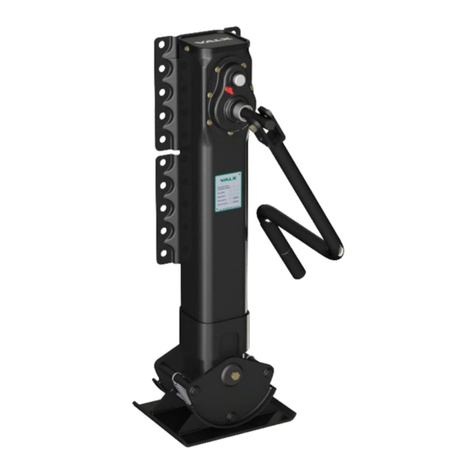
Valx WSM DRUM Instruction manual

Document code: WSM_2051-04 Date: October 2020
WSM DRUM
WORKSHOP MANUAL DRUM BRAKES


WSM_2051-04 3
For additional information on assembly, disassembly, adjustments, maintenance and repair,
contact VALX B.V.:
De Amert 700C
5462 GH Veghel
The Netherlands
Tel: +31 (0)88 405 88 00 (general)
Fax: +31 (0)88 405 88 20
E-mail: [email protected] (general)
www.valx.eu
Document code: WSM_2051-04
Copyright © 2020
Revision summary
Date Revision number Comment
June 2010 01 Initial version
August 2011 02 -
December 2011 03 Address update
October 2020 04 General update
This document and all information herein is and remains at all times the exclusive property of VALX B.V. and shall not - in
whole nor in part - without the prior wrien permission of VALX B.V. be disclosed to any other person, published in any form
of publicity or news story, copied, photographed, reproduced or stored in any retrieval system of any nature.
The information in this document has been prepared solely for the purpose of providing information about assembly,
disassembly, repair and maintenance on the trailer axle and the suspension system (hereafter: trailer axle). It has been
compiled in good faith by VALX B.V. and is provided without any express or implied warranty as to its completeness or
accuracy. We reserve the right to make amendments to this document to reect further developments.
The original English text in this document will be legally binding and shall prevail in case of any variance between the English
text and a translation. As any translation may be imprecise and inaccurate in whole or in part, VALX B.V. does not accept any
risk, liability and responsibility for any translation.
Any quotations, oers and agreements relating to goods to be delivered and/or services to be provided by VALX B.V. shall
always be subjected to VALX B.V.’s Terms of Sale and Delivery. All other terms and conditions are expressly rejected.
© 2020 VALX B.V. All rights reserved.

4 WSM_2051-04
Preface
Use of this manual
This Workshop Manual is intended for trained and qualied service technicians to enable them to perform all required
maintenance and repair tasks on VALX products in an ecient, safe and environmentally sound way.
TAKE THE TIME TO READ THIS MANUAL THOROUGHLY BEFORE PERFORMING ANY MAINTENANCE OR
REPAIR TASK.
KEEP THIS MANUAL IN A SAFE PLACE, IN THE WORKSHOP.
THIS MANUAL REPLACES ALL PREVIOUS VERSIONS, IF ANY.

WSM_2051-04 5
Conventions
In this manual:
- The steps required to perform a certain task are always numbered. The procedures must imperatively be carried out
in the order given.
- Enumerations (without a prescribed order) are always preceded by a dash (-).
- The words ‘left’ and ‘right’ are used to indicate a certain part or assembly as viewed from the perspective of the
service technician who is doing the job.
- “VALX” is used as a substitute for “VALX B.V.”
NOTE
The VALX drum brake trailer axle has been designed for 0-oset wheels.
0-offset
0
Document code
The document code of this manual can be found in the footer of each page. The document code consists of two elds:
- Document type (WSM = Workshop Manual, TBM = Trailer Builder Manual, DM = Driver Manual)
- Document number
The third eld contains the document revision number.
Related documents
The following related documents are available:
- Trailer Builder Manual (TBM_20XX)
- Driver Manual (DM_20XX)
- Air suspension systems (WSM_20XX)
Conversion SI-units – imperial units
SI-units -> non-metric units non-metric units -> SI-units
1 kg ≈ 2.2046 lb 1 lb ≈ 0.453592 kg
1 mm = 0.03937 in 1 in = 25.4 mm
1 m = 3.28 ft 1 ft = 0.3048 m
1 km = 0.62 mile 1 mile = 1.609 km
1 Nm ≈ 0.7376 ft-lb 1 ft-lb ≈ 1.3558 Nm
1 MPa (10 Bar) = 145 psi 1 psi = 0.0068966 MPa (0.0689 bar)
Service and technical support
For information about specic maintenance or repair tasks, adjustments or test procedures that are beyond the scope of
Make sure that you have the axle type code at hand. See chapter 2.

6 WSM_2051-04
Table of contents
Pictograms in this manual 7
Symbols 8
Symbols for quick reference 11
1 General safety instructions and regulations 13
1.1 General 13
1.2 This manual 13
1.3 Decals and instructions on the product 13
1.4 Warranty and original VALX parts 13
1.5 Maintenance and repair 13
1.6 A contribution to the protection of our environment 14
1.7 Safety instructions when working on the brake system 14
1.8 Safety instructions when working on the wheel hub unit 14
1.9 Safety instructions when working on the axle beam 14
2 Explanation of the axle type code 15
2.1 Locationoftheidenticationplate 15
2.2 Informationontheidenticationplate 15
2.3 Ordering of parts 16
3 Maintenance chart 17
4 Tightening torques 18
5 Axle complete 19
5.1 Overview 19
6 Preparatory actions 20
6.1 Place the wheel chocks 20
6.2 Jack up the trailer 21
6.3 Remove the wheel(s) 22
6.4 Install the wheel(s) 23
7 Brake system 25
7.1 Safety instructions 25
7.2 Overview 25
7.3 Periodic maintenance and inspection 26
7.4 Disassembly, assembly and adjustments 32
8 Wheel hub unit 51
8.1 Safety instructions 51
8.2 Overview 51
8.3 Periodic maintenance and inspection 52
8.4 Disassembly, assembly and adjustments 53
9 Axle beam 63
9.1 Safety instructions 63
9.2 Overview 63

WSM_2051-04 7
Pictograms in this manual
Pictograms for general alerts
In this manual the following pictograms and symbols may be used for general alerts:
NOTE
Important instruction, recommendation or tip that you must always observe.
If the safety instruction is not observed, a potential hazardous situation can occur, causing personal
injury or damage to the product, the workshop or the environment.
If the safety instruction is not observed, an imminent hazardous situation will occur, causing severe
personal injury or death.
Pictogramsforspecicalerts
In this manual the following pictograms and symbols are used for specic alerts:
CAUTION
Risk of injury due to hazardous dusts.
CAUTION
Risk of injury due to heavy weight.
CAUTION
Risk of injury: crushing of ngers.
>25 kg
CAUTION
Weight exceeds 25 kg.

8 WSM_2051-04
Symbols
Sometimes, a picture or a pictogram tells more than text can. For that reason, the maintenance, assembly and
disassembly procedures in the chapters 5 through 9 mainly consist of graphical instructions.
In these graphical instructions the following pictograms may be used:
Tools
32
Use a spanner
The value in the left-hand corner is the width across ats.
8
Use a ring spanner
The value in the left-hand corner is the width across ats.
290 Nm
Use an appropriate torque wrench
Tighten the fastener to the torque (in Nm) given in the left-hand corner.
1 mm
Use a feeler gauge
The value in the left-hand corner is the thickness of the feeler gauge.
14
Use a hex key
The value in the left-hand corner is the hex key size.
Use a pair of circlip pliers
Use a hammer
Use an appropriate wire brush
Use a chisel
Use a crowbar
Use an inside calliper

WSM_2051-04 9
Special tools
Use the central nut locking tool
75
Usethesocketwrench(widthacrossats75)
The value in the left-hand corner is the width across ats.
Usethespecialsockettool(widthacrossats103)
The value in the left-hand corner is the width across ats.
Lubricants
Optimol
White Paste
Lubricate with Optimol White Paste
Mobilith SHC 220
Lubricate with Mobilith SHC 220
Renolit HLT1
Lubricate with Renolit HLT1
WABCO ABS
sensor grease
Lubricate with ABS sensor grease
Clean with an appropriate degreasing agent

10 WSM_2051-04
Miscellaneous
Release the brake
Release the brake prior to this step.
Actuate the brake
Actuate the brake prior to this step.
Visual check
Check for damage, wear, corrosion, correct fastening.
Thissteprequirestwotrainedandqualiedservicetechnicians
Clean with a lint free cloth
Measure

WSM_2051-04 11
Symbols for quick reference
Place the wheel chocks (see § 6.1 )
Jack up the trailer (see § 6.2 )
Remove the wheel(s) (see § 6.3 )
Install the wheel(s) (see § 6.4 )
Remove the brake shoes (see § 7.4.1 )
Install the brake shoes (see § 7.4.2 )
Remove the dust cover (see § 7.4.3 )
Install the dust cover (see § 7.4.4 )
Remove the brake drum (see § 7.4.5 )
Install the brake drum (see § 7.4.6 )
Remove the slack adjuster (see § 7.4.7 )
Install the slack adjuster (see § 7.4.8 )

12 WSM_2051-04
Adjust the slack adjuster (see § 7.4.9 )
Remove the brake cylinder (see § 7.4.10 )
Install the brake cylinder (see § 7.4.11 )
Remove the S-cam and the S-cam bearing (see § 7.4.12 )
Install the S-cam and the S-cam bearing (see § 7.4.13 )
D
E
F
C
2
3
4
C
D
A
B
E
F
B
A
5 6
1
SCALE:1:2
SHEET 3 OF 5
DATE
DATE
FINISH:
GENERAL TOLERANCES:
CHK'D proposal
MATERIAL:
TITLE:
WEIGHT:
A3
DOC NO.
DEBURR AND BREAK
ALL SHARP EDGES
UNLESS OTHERWISE SPECIFIED:
DIMENSIONS IN MILLIMETERS
SYSTEM:
THIRD ANGLE PROJECTION
DO NOT SCALE DRAWING
Solidworks
TR=2040 STR=1200-1300 ABS prepared with slack adjusters
Axle assy drum 9t 420x180 OS=0
REVISION
-
Released
DATE
DATE
-
CHK'D proto
DRAWN
DWG NO.
ABS sensor
24-08-2020
-
CH
DrawingType:
Production
20015422
REV.
DATE
APPROVED
-
-
-
-
-
-
-
-
-
-
-
-
Install the ABS sensor (see § 7.4.14 )
Remove the hub assembly (see § 8.4.1 )
Install the hub assembly (see § 8.4.2 )
Remove the inner/outer bearings (see § 8.4.3 )
Install the inner/outer bearings (see § 8.4.4 )
Install the ABS ring (see § 8.4.5 )

WSM_2051-04 13
1 General safety instructions and regulations
1.1 General
- VALX accepts no liability for any damage or physical injury caused by non-compliance with the safety
instructions and regulations in this manual, or by carelessness during any maintenance or repair task on the
VALX trailer axle.
- Depending on the trailer type, the specic repair or maintenance task(s) that have to be carried out, the
workshop conditions, the environmental circumstances and the cargo that may be loaded, additional safety
instructions may be applicable. As VALX has no direct control over these specic working conditions or
trailer congurations, it is the workshop’s sole responsibility to ensure that the national accident prevention
guidelines and the local Health and Safety regulations are adhered to. Please inform VALX immediately if
you have dealt with unsafe situations that have not been described.
1.2 This manual
- Read this manual thoroughly before performing any maintenance or repair task on the trailer axle.
- Keep this manual for future reference. Retain the manual in a safe place in the workshop.
- Carry out the procedures in the order given. Do not change the order of the steps.
1.3 Decals and instructions on the product
- Decals or instructions ed on the product are part of the safety features provided. They must not be
covered or removed, but must be present and legible throughout the entire life of the product. Damaged or
illegible decals and instructions must be replaced or repaired immediately.
1.4 Warranty and original VALX parts
- All products of VALX are covered by warranty as stipulated in the “VALX Warranty Conditions”. The
“VALX Warranty Conditions” can also be downloaded from our website www.valx.eu.
- Modication and / or conversion of the product without the wrien consent of VALX is not allowed at the
risk of forfeiting all warranty rights.
- When replacing parts, ONLY use original VALX spare parts. Parts approved by VALX for use in the product
periodically undergo severe tests. As a result, VALX is able to warranty the quality of these parts.
- VALX can not assess for every single third-party product whether it can be used for the VALX product
without any safety risk. This applies even if such products have already been tested by an accredited test
authority. Therefore, the VALX warranty becomes null and void if spare parts other than original VALX
parts are used.
1.5 Maintenance and repair
- In order to maintain the safe operation and the roadworthiness of the trailer, all maintenance tasks must be
carried out according to the prescribed VALX service intervals (see the maintenance chart in chapter 3), and
in accordance with the operation and service instructions of the trailer builder.
- Maintenance and repair is strictly reserved to trained and qualied service technicians.
1.5.1 Before starting work
- Make sure that the trailer is properly secured against rolling. See chapter 6.
- Make sure that unauthorised persons have no access to the working area.
- Make sure that the working area is suciently lit and ventilated.
- Dress properly. Do not wear torn or loose ing clothes, but wear protective clothing. Remove jewelery,
watches, etc. to prevent them from being caught in moving parts.
- Wear protective shoes and keep long hair out of the way.
- Use a dust mask when advised.

14 WSM_2051-04
1.5.2 During work
- Stay alert and watch what you are doing. Use common sense. Do not work on the product when you are
tired or have been taking alcohol, medicine or drugs. Do not smoke.
- Use a hoist when lifting 25 kg or more. Only use suitable and technically perfect lifting devices with
adequate lifting capacity built in compliance with all safety measures. Fastening of loads and instructions to
the operator of the lifting device are restricted to experienced personnel who are within sight or sound of the
operator of the lifting device.
- Only use tools, parts, materials, lubricants and service techniques that were approved by VALX. Do not use
contaminated or used lubricants. Used lubricants, cleansing agents and expended parts must be disposed of
in an environmentally safe way.
- Avoid bodily contact with lubricants.
- Never use worn tools and do not leave tools behind on the trailer axle or on the trailer.
- Never weld on any part of the trailer axle or suspension without the prior wrien permission of VALX.
- Never re-use self-locking xing materials. Always replace them.
1.5.3 Whenworkisnished
- Inspect the product. Check for damage, leakage or defects. Any part removed for maintenance or repair
purposes must be reed and checked immediately upon completion of the work.
- Do not clear a product for operation unless it was established that it is absolutely safe and in perfect working
order.
1.6 A contribution to the protection of our environment
Please obtain information about recycling or environmentally friendly processing of parts and materials that
have been replaced during maintenance or repair tasks.
Almost all used lubricants are considered to be chemical waste. For the disposal of these a specialized company
must be contacted.
1.7 Safety instructions when working on the brake system
See chapter 7.
1.8 Safety instructions when working on the wheel hub unit
See chapter 8.
1.9 Safety instructions when working on the axle beam
See chapter 9.

WSM_2051-04 15
2 Explanation of the axle type code
2.1 Locationoftheidenticationplate
Type: Axle nr.:
Prod. nr.:
Brake
appr.:
Perm. axle
cap. stat.:
V Max.:
km/h
ABHD
CFEG
A
C
H
D
F
B
E
G
D
E
F
C
2
3
4
C
D
A
B
E
F
B
A
5 6
1
SCALE:2:1
SHEET 1 OF 1
DATE
DATE
FINISH:
GENERAL TOLERANCES:
CHK'D proposal
MATERIAL:
TITLE:
WEIGHT:
A3
DOC NO.
DEBURR AND BREAK
ALL SHARP EDGES
UNLESS OTHERWISE SPECIFIED:
DIMENSIONS IN MILLIMETERS
SYSTEM:
THIRD ANGLE PROJECTION
DO NOT SCALE DRAWING
Solidworks
Tag axle
See notes
REVISION
-
Released
DATE
DATE
-
CHK'D proto
DRAWN
DWG NO.
Type plaatje manuals
05-08-2020
-
CH
DrawingType:
Production
20015409
REV.
DATE
APPROVED
-
-
-
-
-
-
-
-
-
-
-
-
2.2 Informationontheidenticationplate
The identication plate consists of the following elds:
A Axle type code
The axle type code is built up as shown in the table below.
Brake
type
Brake
diameter
Wheel Steering Load capacity
(in kg)
Wheel bolts
Drum brake D
Disk brake (rotor) R
Small 300x200 mm (17.5” rimsize) S
Medium 370 mm disk (19.5” rimsize) M
Medium 360x200 mm drum (19.5” rimsize) M
Large 430 mm disk (22.5” rimsize) L
Large 420x180 drum (22.5” rimsize) L
Extra large 420x220 (22.5” rimsize) X
Single wheel / 0-oset S
Double wheel D
Single wheel / 120-oset O
Rigid axle X
E2! energy axle E
E2!HD energy axle G
Forced steering axle F
Self steering axle S
Heavy duty rigid axle H
9.000 kg 09
10.000 kg 1 0
11.000 kg 1 1
12.000 kg 1 2
13.000 kg 1 3
6 wheel bolts 0 6
8 wheel bolts 0 8
10 wheel bolts 1 0
B Brake approval (with test report number)
C Permissible axle capacity static (in kg)
D Barcode (axle number )
E Barcode (production number)
F Maximum allowable speed (in km/h)
G Production number

16 WSM_2051-04
H Axle number
The axle number is built up as shown in the table below.
Axle type
Axle specs
ID number
12345678
Disk brake axle 17,5” incl. ABS 1/9 4
Disk brake axle 17,5” 1/9 5
Disk brake axle 19,5” incl. ABS 1/9 6
Disk brake axle 19,5” 1/9 7
Disk brake axle 22,5” incl. ABS 1/9 8
Disk brake axle 22,5” 1/9 9
Drum brake axle 17,5” incl. ABS 2 4
Drum brake axle 17,5” 2 5
Drum brake axle 19,5” incl. ABS 2 6
Drum brake axle 19,5” 2 7
Drum brake axle 22,5” incl. ABS 2 8
Drum brake axle 22,5” 2 9
Single mounting OS = 0 0
Double mounting 1
Single mounting OS = 120 2
Rigid axle (X) 0
Forced steering axle (F) 1
Self steering axle (S) 2
Energy axle (E/G) 3
Heavy duty axle (H) 4
Load capacity 9.000 kg 9
Load capacity 10.000 kg 0
Load capacity 11.000 kg 1
Load capacity 12.000 kg 2
Load capacity 13.000 kg 3
Hub with 6 wheel bolts 6
Hub with 8 wheel bolts 8
Hub with 10 wheel bolts 0
Unique ID number axles 0 1
9 9
2.3 Ordering of parts
See the parts ordering procedure on www.valx.eu or contact VALX at tel: +31 (0)88 405 88 00.

WSM_2051-04 17
3 Maintenance chart
NOTE
As road conditions may vary from one country to another, and specic use of the trailer axle may
dier per user, the maintenance intervals given below are only indicative. The maintenance tables
dierentiate between on-road use (X) and o-road use (0).
Inspection item Maintenance task See section Maintenance interval
every 3
months
every 6
months
every
year
every 3
years
every 5
years
Brake lining Check the thickness of the brake lining
through the hole in the dustcover.
(minimum thickness: 5 mm)
7.3.1 0 / X
Brake drum Check for cracks, damage or wear - 0 X
Check the internal diameter of the brake
drum when replacing brake shoes.
7.3.2
Brake cylinder 1Check the general condition of the
brake cylinder (connection, damages,
corrosion, leakage)
- 0 X
Slack adjuster Check the correct functioning 7.3.4 0 X
Lubricate the slack adjuster
(2 grease nipples per axle)
7.3.5 0 X
S-cam bearing Lubricate the S-cam bearing
(4 grease nipples per axle)
7.3.6 0 X
All parts of the
wheel hub unit
Check for damage or wear - 0 X
Tyres Check for damage or uneven wear - X / 0
Outer and inner
bearing
Check for play 8.3.1 0 X
Outer and inner
bearing
Replace bearing and bearing grease 8.4.3 & 8.4.4 0 X
Seal Replace 8.4.3 & 8.4.4 0 X
Wheel nuts 2Check for correct fastening 6.4 0 X
Axle beam Check for irregularities, the brake
cylinder seat and the s-cam bearing
bracket
- 0 X
Check for damage, waer or corrosion - 0 X
1Always check that the draining plug(s) at the boom of the brake cylinder have been removed.
2Always check the correct fastening of the wheel nuts after the rst journey with a loaded trailer and whenever the
wheel in question has been replaced.

18 WSM_2051-04
4 Tightening torques
NOTE
Always tighten or check the fasteners with a calibrated torque wrench.
1
5
32
6
4
1
Torques
Subassembly Chapter Item Size Widthacrossats
Inspection When replacing
Brake system 7 1 Dust cover bolt M8 13 20 Nm 22 Nm ± 4 Nm
2Brake cylinder nut M16 x 1.5 24 175 Nm 210 Nm – 30 Nm 1
3Set nut yoke M16 x 1.5 24 60 Nm 65 Nm ± 4 Nm 1
4Ball bearing nut M8 13 20 Nm 22 Nm ± 4 Nm
Wheel hub unit 8 5 Central nut M55 x 1.5 75 N.A. 630 Nm ± 30 Nm
6Wheel nuts M22 x 1.5 32 600 Nm 630 Nm ± 30 Nm
1The torque refers to WABCO brake cylinders. If other brake cylinders are used, the brake cylinder nuts must be
tightened to the torque specied by the supplier.

WSM_2051-04 19
5 Axle complete
5.1 Overview
D
C
B
A
NOTE
The VALX drum brake trailer axle has been designed for 0-oset wheels.
A Brake system (drum brake) (see chapter 7 )
B Wheel hub unit (see chapter 8 )
C Air suspension system
D Axle beam (see chapter 9 )

WSM_2051-0320
6 Preparatory actions
6.1 Place the wheel chocks
1
Position the trailer on an even surface and use wheel chocks to secure the trailer against rolling away.
Table of contents
Other Valx Lifting System manuals
Popular Lifting System manuals by other brands

NIFTYLIFT
NIFTYLIFT SD34T Series Operating/safety instructions

AMGO
AMGO HS-12 Installation and service manual

Braun
Braun NCL954 Service manual

Tractel
Tractel Davitrac Installation, operating and maintenance manual

morse
morse 400A-72SS-114 Operator's manual

Skyjack
Skyjack SJIII 3220 operating & maintenance manual