VAN DER ENDE Enmix Light User manual

Assembly Manual
Enmix Light
Agitator/mixer
Version: 1.9
Date: February 2022

Van der Ende Groep. · Aartsdijkweg 23, 2676 LE, Maasdijk · Telefoon 0174 515050
IBAN NL71 RABO 0340341610 · KvK Den Haag 27230471 · Btw-nummer NL8000.78.378.B01 · [email protected] · www.vanderendegroep.nl
Pagina 2 van 16
Foreword
This assembly manual is intended for use by technicians who are qualified to install this type of
machine. It is not a user manual.
The Enmix Light has no real function when it is not connected to the appropriate facility for this
installation and consequently it is classified as an unfinished machine. This assembly manual contains
only those instructions pertinent to the safe assembly, correct installation and safe operation of the
Enmix Light. It does not contain operating instructions for the entire installation. The approved
installer should provide these.
Each chapter is numbered and, where appropriate, the chapters are divided into sections. The table of
contents on page 3 gives an overview of the chapters and sections and a reference to the appropriate
page number.

Van der Ende Groep. · Aartsdijkweg 23, 2676 LE, Maasdijk · Telefoon 0174 515050
IBAN NL71 RABO 0340341610 · KvK Den Haag 27230471 · Btw-nummer NL8000.78.378.B01 · [email protected] · www.vanderendegroep.nl
Pagina 3 van 16
Table of Contents
Foreword ...................................................................................................................................... 2
Table of Contents .......................................................................................................................... 3
1Identification .......................................................................................................................... 4
1.1 General .......................................................................................................................... 4
1.1.1 Description of the machine .......................................................................................... 4
1.1.2 Specifications.............................................................................................................. 4
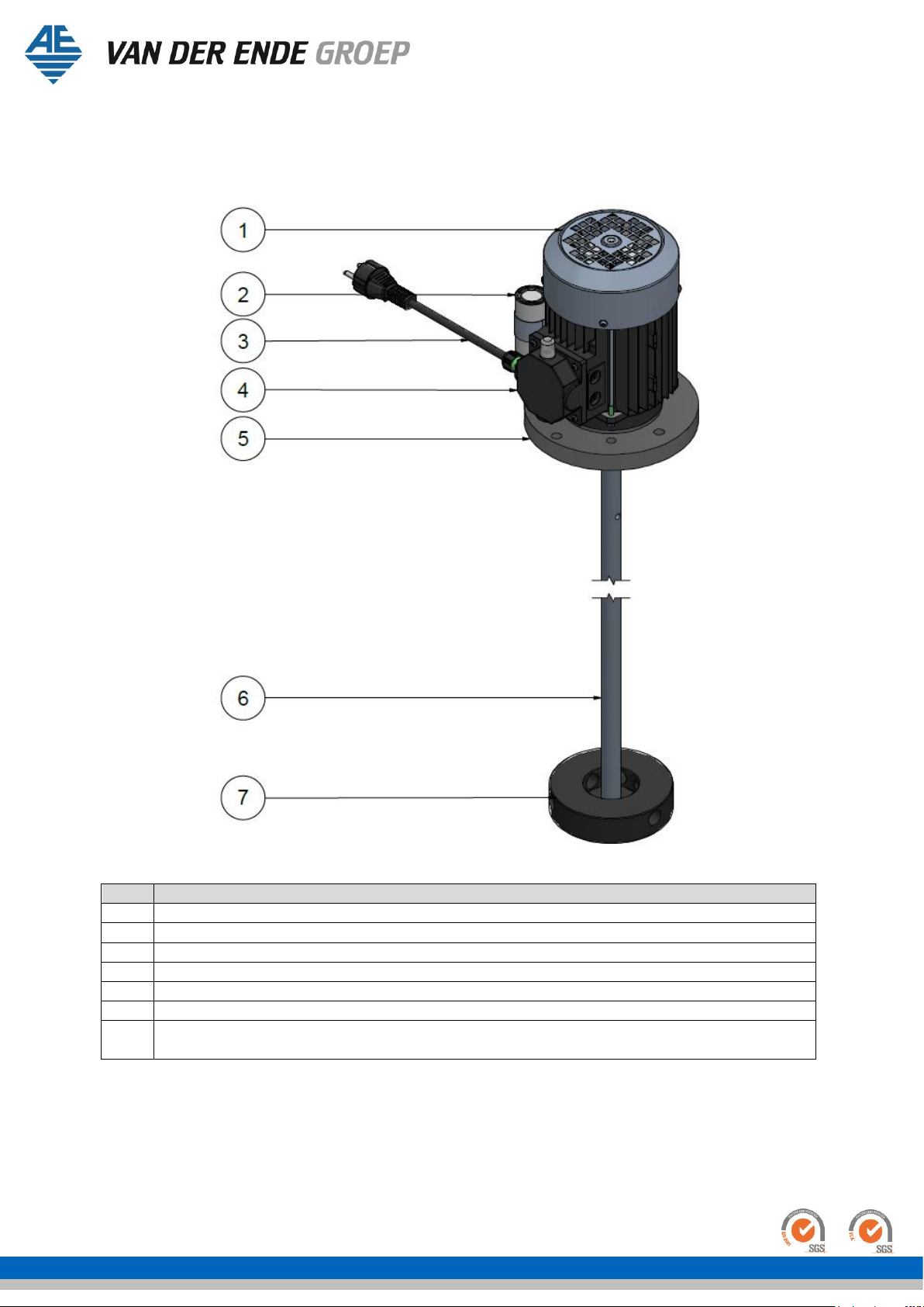
1.1.3 Schematic diagram of the machine............................................................................... 5
1.2 Operation....................................................................................................................... 6
1.3 Use................................................................................................................................ 7
1.4 Users ............................................................................................................................. 7
1.5 Media............................................................................................................................. 7
1.6 Operating environment ................................................................................................... 7
1.7 Guarantee conditions ...................................................................................................... 8
1.8 CE mark ......................................................................................................................... 8
1.9 Residual risks ................................................................................................................. 8
2Description............................................................................................................................. 9
2.1 General .......................................................................................................................... 9
2.2 Operating principle ......................................................................................................... 9
2.3 Transport and storage..................................................................................................... 9
3Safety instructions .................................................................................................................10
4Assembly ..............................................................................................................................11
4.1 General .........................................................................................................................11
4.2 Installation instructions ..................................................................................................11
4.3 Delivery checklist ...........................................................................................................11
4.4 Assembly ......................................................................................................................12
4.5 Installation ....................................................................................................................13
4.6 Connecting / start-up .....................................................................................................13
5Operation/using for the first time............................................................................................14
6Maintenance..........................................................................................................................14
6.1 Regular checks ..............................................................................................................14
7Malfunctions..........................................................................................................................14
8Declaration of Conformity.......................................................................................................15
Notes...........................................................................................................................................16

Van der Ende Groep. · Aartsdijkweg 23, 2676 LE, Maasdijk · Telefoon 0174 515050
IBAN NL71 RABO 0340341610 · KvK Den Haag 27230471 · Btw-nummer NL8000.78.378.B01 · [email protected] · www.vanderendegroep.nl
Pagina 4 van 16
1Identification
This overview contains general information about the machine. The aim of this document is to define
the purpose, the overall functioning and the application field of the machine.
1.1 General
1.1.1 Description of the machine
The Enmix Light consists mainly of four components:
1. Electric motor (1)
2. Assembly plate; PVC black (5)
3. Mixing shaft; stainless steel 316, max. length: 1250 mm (6)
4. Mixing disc; PVC black (7)
A mounting frame which can be placed between the Enmix Light and the liquid reservoir is optionally
available. The material for this frame is stainless steel 304. It’s also possible to request the mounting
frame as stainless steel 316. This all must be specifically requested.
The purpose of the machine is to keep liquids in motion in order to promote their dissolution and
prevent precipitation. The Enmix Light drive unit must be mounted above a fertilizer bin or other
container of liquid substances such that the mixing disc will continue to rotate below the surface of
the liquid up to the lowest liquid level.
1.1.2 Specifications
Standard specifications Enmix Light
Motor power
0,37 kW
Sealant
IP55
Condenser
12,5 µF
Material
Stainless steel 316
Engine specifications
Frequency
Supply
voltage
Current
Motor
revolutions
Fase
Cos φ
Weight
No. VDEG
50 Hz
200 V
3.0 A
1400 RPM
3F
0.69
6.0 kg
53010460
50 Hz
230 V
3.0 A
1370 RPM
1F
0.96
6.2 kg
53010400
50 Hz
230 V /
400 V
1.99 A /
1.15 A
1400 RPM
3F
0.69
5.4 kg
53010440
60 Hz*
230 V
3.6 A
1650 RPM
1F
0.99
6.2 kg
53010420
Table 1: Specifications
* cURus certificated

Van der Ende Groep. · Aartsdijkweg 23, 2676 LE, Maasdijk · Telefoon 0174 515050
IBAN NL71 RABO 0340341610 · KvK Den Haag 27230471 · Btw-nummer NL8000.78.378.B01 · [email protected] · www.vanderendegroep.nl
Pagina 5 van 16
1.1.3 Schematic diagram of the machine
Below are the main components of the Enmix Light, represented by a number and corresponding
name.
Figure 1: Overview of components Enmix Light
No.
Description
1
Electric motor
2
Capacitor 12.5 µF
(Only at 1-fase motors)
3
Cable + Plug (2 meter)
(Only at 1-fase motors)
4
Terminal box + thermal protection
(Only at 1-fase motors)
5
PVC mounting plate
6
Mixer shaft
Length max. 1250 mm
7
PVC mixing disc
Ø128 mm @50Hz
Ø112 mm @60Hz
Table 2: Main components of the Enmix Light

Van der Ende Groep. · Aartsdijkweg 23, 2676 LE, Maasdijk · Telefoon 0174 515050
IBAN NL71 RABO 0340341610 · KvK Den Haag 27230471 · Btw-nummer NL8000.78.378.B01 · [email protected] · www.vanderendegroep.nl
Pagina 6 van 16
1.2 Operation
The Enmix Light is supplied without controls. The Enmix Light 230 Vac version is supplied with locking
thermal protection and with approximately two meters of cable.
The Enmix Light must be connected to a switched socket outlet or a timer to operate the machine.
The reset button for the thermal protection is located in the cover of the motor’s terminal box.
Figure 2: Location of the reset button
Reset button
Thermal switch

Van der Ende Groep. · Aartsdijkweg 23, 2676 LE, Maasdijk · Telefoon 0174 515050
IBAN NL71 RABO 0340341610 · KvK Den Haag 27230471 · Btw-nummer NL8000.78.378.B01 · [email protected] · www.vanderendegroep.nl
Pagina 7 van 16
1.3 Use
The Enmix Light is intended to be used for the mixing and continuous agitation of liquids containing
additives. To achieve this, the Enmix Light must be mounted above a fertilizer bin or other container
with the mixing disc in the liquid.
In connection with the chemical resistance properties of the materials which make up the Enmix, the
Enmix cannot and must not be used in just any medium. The manufacturer should be contacted for
questions and advice in this matter. Upon request, the manufacturer can also provide a list of suitable
and unsuitable chemicals.
Under no circumstances may the media contain long fibers (longer than 5mm), neither may viscous
media (>1000 mPas) be mixed with the Enmix Light.
The supplier or the manufacturer should be contacted for advice on the use of media and the Enmix
Light in general.
The Enmix Light is not intended to be used without being placed on a liquid reservoir. The Enmix is
not intended to be used for the purpose of processing foodstuffs.
1.4 Users
Intended users are at least 18 years of age, employed by the company where the Enmix Light is
installed and appointed by the management as the competent and qualified person to operate the
Enmix Light.
Unintended users are users who do not meet the above requirements. Unintended users are all users
who, by using the Enmix Light, create unsafe situations or cause danger to themselves and/or others
1.5 Media
Placing an image/comment in relation to the Enmix Light should always be discussed in advance with
the producer/supplier. If this is not observed, any consequential damage can be recovered from this
person/company.
1.6 Operating environment
The Enmix Light is intended to be used as a mixer that is mounted on a fertilizer bin or other
container. When installing the mixer, care should be taken to ensure there is sufficient free space
around the Enmix Light. The Enmix Light must be mounted on a fertilizer bin or other container of
liquid substances.
The Enmix Light is not intended for use in explosive surroundings.

Van der Ende Groep. · Aartsdijkweg 23, 2676 LE, Maasdijk · Telefoon 0174 515050
IBAN NL71 RABO 0340341610 · KvK Den Haag 27230471 · Btw-nummer NL8000.78.378.B01 · [email protected] · www.vanderendegroep.nl
Pagina 8 van 16
1.7 Guarantee conditions
This product is guaranteed for a period of 6 months from the proven date of commissioning, with a
maximum date of 2 years after the date of production. The proven date of commissioning means the
date on which the machine was installed.
If a claim is made on the guarantee, the parts in question must be submitted to the manufacturer for
evaluation.
The warranty will cease to be valid if any of the following conditions apply:
•Improper use or installation
•Repeatedly ignoring the advice of the supplier and/or manufacturer
•Repair, maintenance or use by unauthorized persons
•Use of unsuitable connections with regard to power supply or cables
•Use of the machine in an unsuitable environment
•Intentional damage or adaptations to the machine
The guarantee conditions are conform to the METAALUNIE CONDITIONS (the Dutch organization for
small and medium-sized enterprises in the metal industry) published in January 2014.
1.8 CE mark
The CE mark relates to compliance with the Machinery, Low Voltage, EMC and PED Directives. The
Enmix Light is an unfinished machine and consequently does not meet all the conditions and essential
safety requirements at the time of delivery. A list of the conditions and safety requirements that the
Enmix Light does not meet at the time of delivery may be obtained from the manufacturer.
The CE mark can be found on the sticker affixed to the motor.
According to the Low Voltage Directive, the Enmix Light is classified as a Class I device.
1.9 Residual risks
It is practically and economically impossible to cover all risks for the full 100%. Furthermore, one of
the risks of the machine may be closely connected to its functionality. The so-called residual risks are
shown in the table below. It is important that the user is aware of the risks involved when using this
machine. All safety regulations should be followed in order to minimize the risks as much as possible.
Risk page No.
Residual risk description
Risk factor
Category
1.
If the mixer is longer than the support legs, which
may or may not be present, the Enmix cannot be
placed in a stable position. This is only applicable
prior to the installation of the Enmix.
1
A
Table 3: List of residual risks

Van der Ende Groep. · Aartsdijkweg 23, 2676 LE, Maasdijk · Telefoon 0174 515050
IBAN NL71 RABO 0340341610 · KvK Den Haag 27230471 · Btw-nummer NL8000.78.378.B01 · [email protected] · www.vanderendegroep.nl
Pagina 9 van 16
2Description
This chapter contains an explanatory description of the machine, which is the background information
that is required to correctly and safely use the machine.
2.1 General
The rotation of the mixer shaft and the mixing disc sets the liquid in the reservoir in motion. The
mixing disc takes in the liquid from above and then sends the liquid downwards and to the side via
the channels in the mixing disc. In the disc there are 3 channels towards the bottom of the disc and 3
channels directly to the side of the mixing disc. This causes the liquid to move as shown in Figure 3.
The standard direction of rotation of the mixing disc is clockwise (viewed from above).
Figure 3: Position of the mixing disc
2.2 Operating principle
The Enmix Light construction comprises a motor and an extended shaft to which a mixing disc has
been attached. The shaft can be customised to fit every fertilizer bin or other container of liquid
substances shorter or shallower than 140 cm. The mixing disc must be mounted at least 10 cm from
the bottom and must be able to rotate freely while submerged in the liquid.
The material used is predominantly stainless steel type 316 and POM black. When working with low
pH values (under pH4) or with other stronger chemicals ensure beforehand whether the material is
sufficiently resistant to these chemicals.
The shaft is not supported. Because the mixing disc propels the liquid in two directions (downwards
and sideways) and from the centre (from the top), the shaft remains balanced.
It is recommended to check the mixing disc once a month to ensure that it is not clogged.
2.3 Transport and storage
The Enmix Light is transported and should be stored in special packaging. The Enmix is transported as
a complete product, the shaft length should be adjusted at the end-user by an approved installer.
When storing the Enmix Light, care must be taken not to allow the mixer shaft and, where
appropriate, the shaft guide to bend.

Van der Ende Groep. · Aartsdijkweg 23, 2676 LE, Maasdijk · Telefoon 0174 515050
IBAN NL71 RABO 0340341610 · KvK Den Haag 27230471 · Btw-nummer NL8000.78.378.B01 · [email protected] · www.vanderendegroep.nl
Pagina 10 van 16
3Safety instructions
Please read this assembly manual carefully and ensure that you observe the safety instructions before
installing or using the Enmix Light.
The Enmix Light may only be used within the application areas for which it has been designed.
The Enmix Light has been designed to operate as a mixer for a system in which liquid media are used.
These media may only contain chemical substances that are compatible with the materials of the
Enmix Light components that come in contact with them. Further information on the application areas
can be found under paragraphs 1.5, 1.6 and 1.7.
Work on the machine or installation of the electrical part of the Enmix Light may only be carried out
by qualified personnel.
Make sure the power supply is connected to a final circuit with an earth connection with a maximum
fuse value of 16A and a circuit breaker with residual current of 30mA.
Add solids gradually to prevent blockage of the mixing discs.
Always follow all assembly and safety instructions. Failure to observe these instructions may cause
serious damage to persons or property.
Safety symbol
Description
Automatic starting machine!
Electric voltage present!
Hot surface!
Rotating parts!
Reading instructions obligated!
Table 4: Safety instructions Enmix Light

Van der Ende Groep. · Aartsdijkweg 23, 2676 LE, Maasdijk · Telefoon 0174 515050
IBAN NL71 RABO 0340341610 · KvK Den Haag 27230471 · Btw-nummer NL8000.78.378.B01 · [email protected] · www.vanderendegroep.nl
Pagina 11 van 16
4Assembly
4.1 General
The Enmix Light is an unfinished product, and consequently the manufacturer cannot install all the
required safety devices such as control logic or an emergency stop. It is, therefore, important that the
approved installer takes care of these requirements.
4.2 Installation instructions
Please make sure that the Enmix Light is out of reach of children at all times.
Advice with regard to dosage rates and types of fertilizer should be obtained from your supplier.
•Make sure the fluid reservoir which the Enmix light is mounted to is placed on a stable surface.
•Make sure that the Enmix Light is firmly attached to the fertilizer bin or container.
•Make sure at all times that the mixing disc can rotate freely.
•Make sure that contact with the agitator-mixer is prevented by placing a safety grid or lid on the
fertilizer bin or container.
During each phase of the assembly the approved installer or the user must ensure that he or she can
work safely. The use of a stepladder or the helping hand of an extra person or persons will make
assembly of the machine easier and safer.
4.3 Delivery checklist
Make sure all components have been delivered prior to commencing assembly. The Enmix light will be
assembled at the supplier before shipping. At every batch of Enmix light there will be an assembly
manual attached.

Van der Ende Groep. · Aartsdijkweg 23, 2676 LE, Maasdijk · Telefoon 0174 515050
IBAN NL71 RABO 0340341610 · KvK Den Haag 27230471 · Btw-nummer NL8000.78.378.B01 · [email protected] · www.vanderendegroep.nl
Pagina 12 van 16
4.4 Assembly
the numbers between parentheses referring to the numbers and parts in Figure 4.
−Measure the depth. from the surface where the mounting plate (5) is assembled to, to the
bottom of the reservoir.
−Shorten the shaft (6) if necessary and ensure that the mixing disc (7) is at least 100 mm
above the bottom of the fluid reservoir.
oThe shaft (6) can be shortened using a hacksaw or cutting disc.
oFile away any burrs.
−Insert the shaft (6) through the opening in the mixing disc (7).
oPlease note that the suction side is facing to the top (see Figure 4).
−Fix the mixing disc (7) to the shaft (6) using two stainless steel set screws m6x16 (8).
−Place the mixing shaft (6) tot the electric motor (1) and fix it to each other with one stainless
steel set screw m5x8.
−Attach the mounting plate (5) to the reservoir or a structure above this.
Figure 4: Assembly of the Enmix light

Van der Ende Groep. · Aartsdijkweg 23, 2676 LE, Maasdijk · Telefoon 0174 515050
IBAN NL71 RABO 0340341610 · KvK Den Haag 27230471 · Btw-nummer NL8000.78.378.B01 · [email protected] · www.vanderendegroep.nl
Pagina 13 van 16
4.5 Installation
−Select a suitable location for the Enmix Light:
oEnsure the mixing disc can rotate freely.
oEnsure the mixing disc rotates +/- 100 mm from the bottom of fluid reservoir
▪see Figure 3
oEnsure that the mixing disc is submerged during standard operation.
oEnsure there is sufficient space around the Enmix Light.
oEnsure there is a socket outlet within a maximum range of 2 metres from the Enmix Light.
oEnsure the Enmix Light is within view of the socket outlet.
−Prepare for installation:
oConsider where to place the Enmix Light.
oMake the necessary arrangements to mount the Enmix Light onto the bin or container.
▪Use the pre-drilled holes in the mounting plate to mount the Enmix Light.
oIn a round bin or container, the water sometimes turns and swirls in one direction instead
of mixing. In consultation with the manufacturer, place a dividing plate in the bin or
container to prevent this from happening or position the Enmix Light away from the
centre.
oEnsure the Enmix Light can be mounted safely onto the bin or container.
▪Request assistance and use practical aids such as a stepladder or a footstool.
−Mount the Enmix Light onto the bin or container.
−Make sure the mixer is fitted with a safety guard and poses no danger to people!
oUse a cover or grid or any other appropriate guard.
−Assemble the mixing disc following Figure 3 and Figure 4. If the assembly of the mixing disc is
done in the wrong way, the fluid can be sprayed upwards. This could create dangerous situations.
4.6 Connecting / start-up
−Check that the Enmix Light is securely mounted.
−Check that the motor and mixing disc are firmly attached to the mounting plate.
−Check that the shaft can rotate freely.
−Check that the mixing disc can rotate freely.
oMake sure there are no obstacles in the way of the mixing disc.
−Make sure that the mixing disc is mounted at least 100 mm from the bottom of the bin or
container.
−Fill the bin or container with liquid up to at least 100 mm above the mixing disc.
−Make sure the mixer is has a safety guard and poses no danger to people!
−Insert the plug in the socket.
oThe Enmix must be within view of the socket outlet.
oThe socket outlet must have an earth connection.
oA switched socket outlet is highly recommended.
−Check the rotational direction. The standard direction, viewed from above, is clockwise.
Note: In most cases, it is not necessary to continue mixing. Operating the Enmix Light with a timer
and/or low water circuit is recommended. This will prevent unnecessary turning and will significantly
increase the lifespan of the machine.

Van der Ende Groep. · Aartsdijkweg 23, 2676 LE, Maasdijk · Telefoon 0174 515050
IBAN NL71 RABO 0340341610 · KvK Den Haag 27230471 · Btw-nummer NL8000.78.378.B01 · [email protected] · www.vanderendegroep.nl
Pagina 14 van 16
5Operation/using for the first time
Use the Enmix Light to dissolve chemical agents in water. Do not dissolve long fibres (longer than
5mm) or viscous agents (viscosity > 1000 MPas) with the Enmix.
•Always make sure that the agents and liquids used are suitable for use in the Enmix Light. The
supplier or manufacturer should be able to send you a list, free of charge, containing a complete
overview of the agents that may or may not be used.
The Enmix Light may be used for acids to a minimum level of pH4.
6Maintenance
The Enmix Light is practically maintenance free. It is recommended to check the installation each
month and to report any defects to the supplier or the manufacturer.
Always disconnect the power supply before performing any maintenance work on the Enmix. Pull the
plug out of the socket.
6.1 Regular checks
Frequency: monthly
•Check that the mounting plate is still firmly attached to the reservoir.
•Check that the motor and reduction gearbox are still firmly attached to the mounting plate.
•Check that the mixer disc can rotate freely.
•Make sure that the mixing disc is mounted at least 100 mm from the bottom of the reservoir.
•Make sure that the mixing disc is free of fixed elements and that all ports are open.
•Check that the mixer shaft is straight
7Malfunctions
Below is a table of possible malfunctions and their cause. Always make sure that the power supply is
disconnected prior to carrying out any repair work to the Enmix Light.
Problem
Cause
Solution
The mixer no longer turns
No power
Check power supply
Thermal protection is switched
off
Remove any large parts in the bin
or container and press the
thermal protection reset button
Condenser is broken
Replace condenser
Thermal protection switches off
repeatedly
Too much dirt on the mixing
disc (clogged)
Remove large parts and press the
thermal protection reset button
Shaft is bent
Contact your supplier
Table 4 Malfunctions and solutions

Van der Ende Groep. · Aartsdijkweg 23, 2676 LE, Maasdijk · Telefoon 0174 515050
IBAN NL71 RABO 0340341610 · KvK Den Haag 27230471 · Btw-nummer NL8000.78.378.B01 · [email protected] · www.vanderendegroep.nl
Pagina 15 van 16
8Declaration of Conformity
EC-DECLARATION OF CONFORMITY
(according to Annex II B of the Machinery Directive 2006/42/EC)
We,
declare under our sole responsibility that the machine:
to which this declaration relates, complies with all the provisions of the following Directives:
and (where applicable) complies with the following standards or other normative documents.
The Netherlands
Maasdijk
14 January 2020
L. van der Ende
Van der Ende Pompen B.V
Aartsdijkweg 23
2676 LE Maasdijk
The Netherlands
Enmix Light agitator-mixer
Machinery Directive 2006/42/EC
Low Voltage Directive 2006/95/EC
EMC Directive 2004/108/EC

Van der Ende Groep. · Aartsdijkweg 23, 2676 LE, Maasdijk · Telefoon 0174 515050
IBAN NL71 RABO 0340341610 · KvK Den Haag 27230471 · Btw-nummer NL8000.78.378.B01 · [email protected] · www.vanderendegroep.nl
Pagina 16 van 16
Notes
Other manuals for Enmix Light
1
Table of contents
Other VAN DER ENDE Mixer manuals