Vanguard Laser Quick start guide

LASER GO-FAST TIP #1:
Read This Rigging Guide First.
Laser Rigging Guide
Laser Radial Laser 4.7

Congratulations on the purchase of your new Laser! The Laser is a very unique boat that can
accommodate many different sized sailors and abilities, due to its three interchangeable rigs. The
Laser, the Radial and the Laser 4.7 all use the same hull and equipment with the exception of the
lower mast and sail.
We suggest that you read through this guide to better familiarize yourself with the parts and rigging
of your new boat. If you have any questions please contact your dealer or call Vanguard’s customer
service at 1-800-966-SAIL.
Image 2
1. Sail Numbers
2. Line Bag
3. Tiller with 48” extension
4. Rudder
5. Daggerboard
6. Battens
7. Boom
8. Upper mast
9. Cleat base with cleats
10. Lower vang block/cleat
assembly
11. Mainsheet ratchet block
12. Spring
13. Forkhead block base
14. 16 mm Forkhead blocks (2)
15. Large traveler block
16. Small traveler block
17. Vang key
18. Pin and ring
19. Double micro block
with becket (2)
20. Small double block with
becket
21. Micro block with becket (2)
22. Micro single block (2)
Unpacking and Preparation: Laser, Radial & Laser 4.7 Standard Delivery Kit
Image 1
1. Sail Numbers
2. Line Bag
3. Tiller with 33” extension
4. Rudder
5. Daggerboard
6. Battens
7. Boom
8. Upper mast
9. Large traveler block
10. Small traveler block
11. Large vang block
12. Small vang block
13. Vang Key
14. Mainsheet ratchet block
15. Spring
16. Bullseye fairlead
17. Clam cleat
Depending of which Laser you have selected (Laser, Radial or Laser 4.7) you will have one of the following sails and corresponding lower masts
located in your delivery kit.
Locate your delivery kit. Depending on which model you have purchased (Pro or Standard) there will be a few differences in some of the
hardware. The differences between the two models are the cunningham, outhaul, vang and tiller extension. Using images 1 or 2, identify the
contents of your kit. To avoid damaging the contents, be sure not to cut into the packaging inside the box.
Above from left to right: Laser lower mast,
Radial lower mast, and Laser 4.7 lower mast.
Above from left to right: Laser sail, Radial sail, Laser 4.7
sail
Your boat rigged will resemble one of the Lasers shown above. From left
to right: Laser, Radial, and Laser 4.7.
Image 2
Image 1
Image 2
Image 2
48
6
1
2
5
5
7
9
10
7
2
4
6
1
8
3
9
10
12
11
14
13
11
12
13
14
15
17
16
18
17
15
16
19
20
21
22
Unpacking and Preparation: Laser, Radial & Laser 4.7 Pro Delivery Kit
3

Useful Knots to Know:
Figure 8 Knot or
Stopper Knot
Square Knot
Bowline
Clove Hitch
Cleat
Nautical Terminology:
Port: Left side of the boat when looking forward
Starboard: Right side of the boat when looking forward
Gunwale: Upper edge of a boat’s side
Leeward: Direction away from the wind
Windward: Direction from which the wind is coming
Bow
Luff
Foot of the Sail
Clew
Leech
Boom Tack
Port Side
Tiller Mainsheet
Starboard Side
Traveler
Stern
Boom Vang
Mast
Daggerboard
Rudder
Cockpit
Gunwale

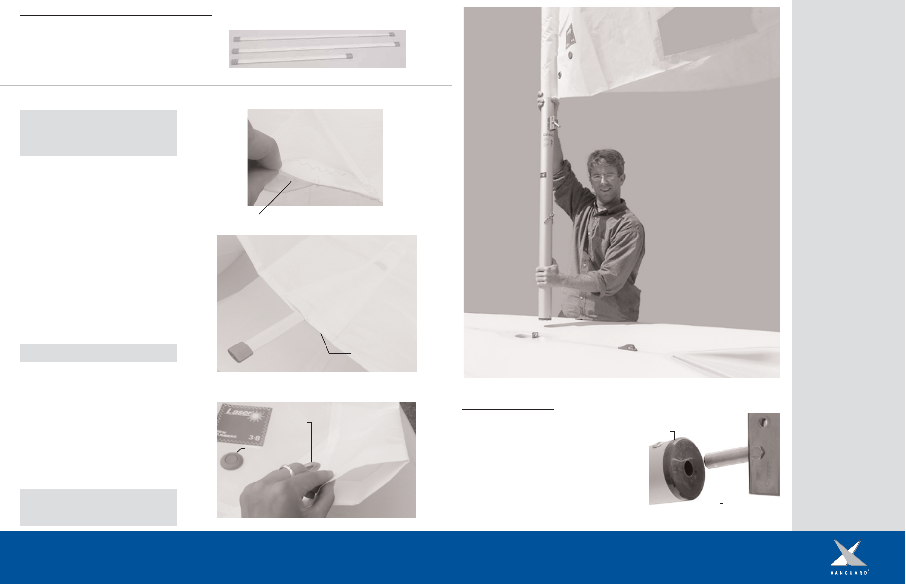
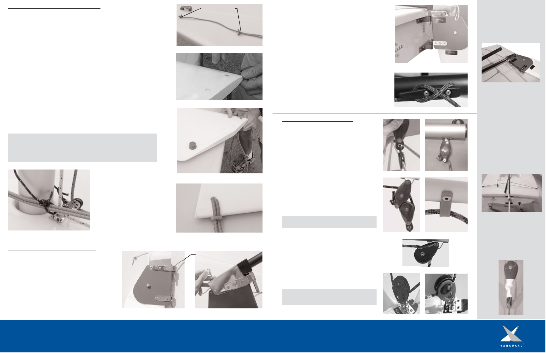
1. From the delivery kit locate the 2, 16mm
forkhead blocks and base. Unscrew the two
screws located by the mast step. Align the
block base over the holes and screw into place
(Figure 9). Attach the forkhead blocks to the
base using the provided pins and rings
(Figure 10).
Here is a list of tools
that we recommend
you have in order to
assemble your new
Laser:
Utility Knife
White Electrical Tape
Phillips Head
Screwdriver
Silicone Sealant
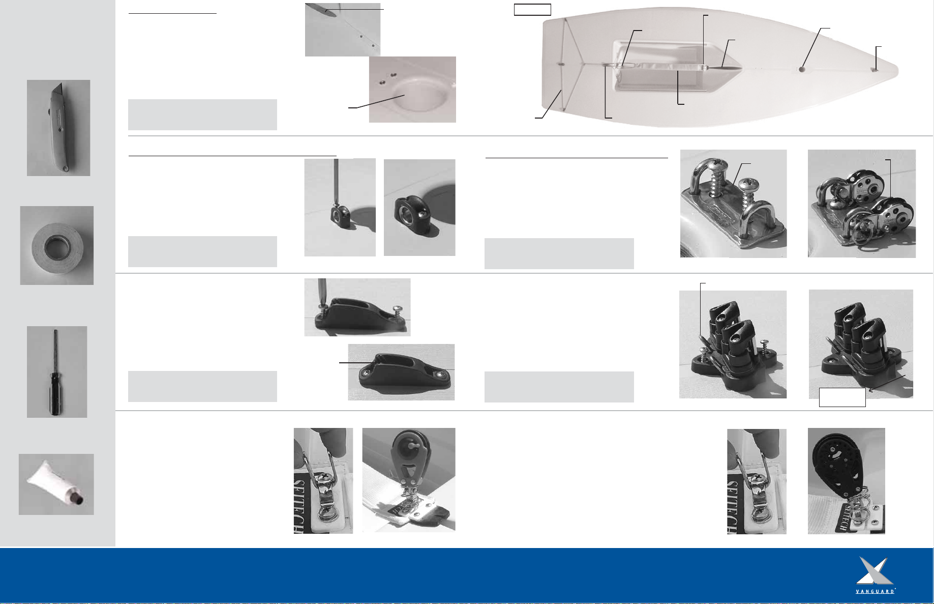
2. Unscrew the set of screws located in front
of the daggerboard well. Align the holes of
the cam cleat and screw into place (Figure 5).
Be sure that the open end of the cleat is
facing towards the cockpit (Figure 6).
3. Locate the ratchet block and spring from
the delivery kit. In the cockpit, at the forward
end of the hiking strap, locate the eyestrap
(Figure 7).
4. Remove the shackle from the bottom of the
ratchet block and place it around the eyestrap
(Figure 7).
5. Place the spring over the eyestrap, and
compress. While the spring is compressed,
attach the block to the shackle with the pin
and ring (Figure 8).
1. In the delivery kit locate the bullseye
fairlead and the clam cleat. Unscrew the two
screws located by the mast step (Figure 3).
Align the bullseye fairlead over the two holes
and screw into place (Figure 4).
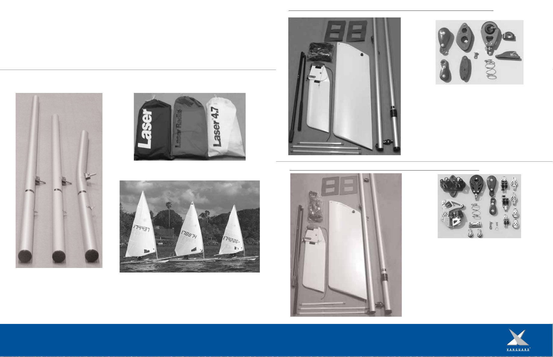
There are a few pieces of hardware that you
will need to install on your new hull before
continuing to rig your Laser. Locate the two
sets of screws that are positioned on the deck
of the boat (Figure A, far right image). One
set of screws will be forward of the
daggerboard well (Figure 1) while the other set
will be aft of the mast step (Figure 2).
Hardware Installation: Laser Standard Models
Tip: Before replacing the screws be sure to dip
them into a silicon based sealant to allow for
a water tight and secure fit.
Hardware Installation: Laser Pro Models
Open end
2. In the delivery kit locate the cleat base
with cleats. Unscrew the two screws located
by the daggerboard well. Align the cleat base
over the two holes and screw into place
(Figure 11). Make sure that the shorter of the
metal fairleads are facing the bow. When
looking at the cleat base from the side, the
cleats should be angled down towards the bow
(Figure 12).
Shorter metal fairleads
Angled down
towards mast
3. Locate the ratchet block and spring from
the delivery kit. In the cockpit, at the forward
end of the hiking strap, locate the eyestrap
(Figure 13).
4. Remove the shackle from the bottom of the
ratchet block and place it around the eyestrap
(Figure 13).
5. Place the spring over the eyestrap, and
compress. While the spring is compressed,
attach the block to the shackle with the pin
and ring (Figure 14).
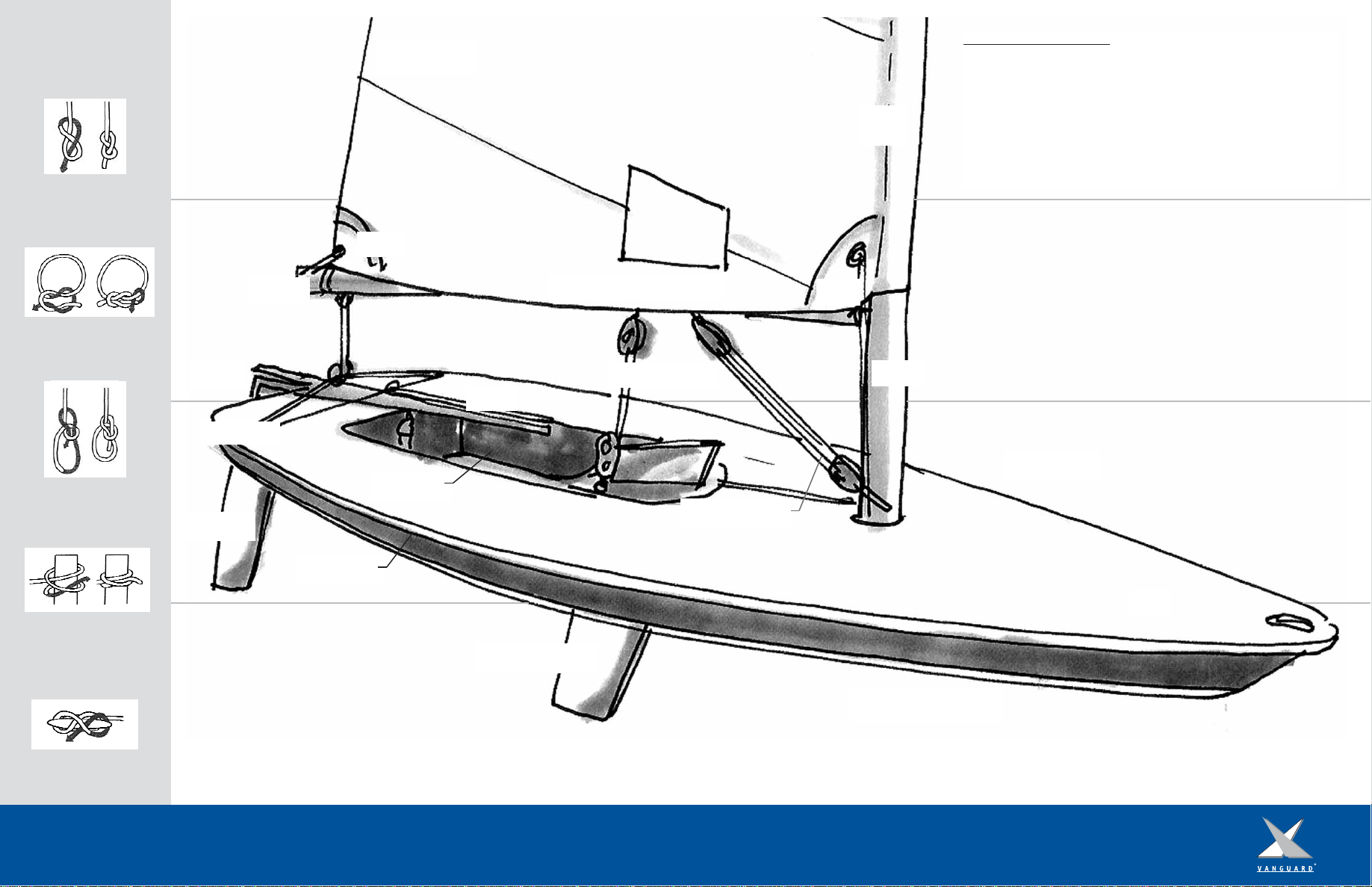
Bow eye
Mast Step
Hiking Strap
Daggerboard Well
Traveler Clam Cleat
Bailer Plug
Ratchet Block Eyestrap
Figure 1
Figure 2
Figure 3 Figure 4
Figure 5
Figure 6
Figure 8Figure 7
Figure 9 Figure 10
Figure 11 Figure 12
Figure 13 Figure 14
Figure A
Hardware Location:
Reminder: Before replacing the screws be sure
to dip them into a silicon based sealant to
allow for a water tight and secure fit.
Reminder: Before replacing the screws be sure
to dip them into a silicon based sealant to
allow for a water tight and secure fit.
Reminder: Before replacing the screws be sure
to dip them into a silicon based sealant to
allow for a water tight and secure fit.
Reminder: Before replacing the screws be sure
to dip them into a silicon based sealant to
allow for a water tight and secure fit.
Block Base 16 mm Forkhead Blocks
Mast Step
Daggerboard Well

1. Locate the traveler line and small traveler block from the
delivery kit. On the stern of the boat locate the two fairleads
(Figure B).
2. Run one end of traveler line through the starboard fairlead
(from bow to stern, Figure 15), then through the small traveler
block (Figure 16) and continue through the port side fairlead
(from stern to bow, Figure 16).
1. Locate the traveler line and small traveler block from the
delivery kit. On the stern of the boat locate the two fairleads
(Figure C).
2. Run one end of traveler line through the starboard fairlead
(from bow to stern), then through the small traveler block and
continue through the port side fairlead (from stern to bow,
Figure 20).
3. Tie a bowline in the port side of the traveler line (Figure 20).
Lead the starboard end of the line through the bowline and pull
until snug (Figure 21).
4. With the starboard end of the line tie an overhand knot to
secure the line (Figure 22).
5. With the tail end of the line, lead it through the cleat and
tie off with a bowline handle (Figure 23).
3. Make a loop in the port side of the line as if you were
going to tie a bowline (Figure 17). Keeping in mind that the
free end of the port side line will be cleated off. Take the
starboard end of the line and complete the bowline by going
through the port loop (Figure 18).
4. Continue the tail end of the port side line through the
cleat and tie off with a bowline handle (Figure 19).
Rigging the Traveler: Laser Standard Models Rigging the Traveler: Laser Pro Models
Figure B: Rigged Laser Standard Traveler Figure C: Rigged Laser Pro Traveler Line
Stern
Bow
Starboard
Side
Port Side
Figure 16
Figure 15
Figure 17
Figure 19
Figure 18
Figure 20 Figure 21
Figure 22 Figure 23
Bowline
Port Fairlead Port Fairlead
Starboard Fairlead
Small Traveler Block
Clam Cleat
Small Traveler Block
Starboard Fairlead
Clam Cleat
Port side of the
line goes
through the
clam cleat
Tie off the
starboard line
with a bowline

Pocket opening
Stepping the Mast
1. Make sure the bow
of the boat is pointing
into the wind and that
their are No Overhead
Electrical Wires in the
Area! Also make sure
that the mast step hole
and mast butt are
perfectly clean; any
sand or dirt in the
mast step will grind
into the gelcoat and
can damage the mast
step.
2. Place the mast butt
against a flat solid
object. By placing a
towel or piece of
cardboard on the
ground it will help
prolong the life of the
plastic mast butt.
3. Lift the mast from
the head of the sail
and walk toward the
mast butt, raising the
mast hand over hand
until vertical.
4. Make sure that the
gooseneck is facing the
stern of the boat
before lifting.
5. Keeping your hands
a good distance apart,
lift the mast over the
mast step hole
(Figure D).
6. Allow the mast to
slide into the step. Do
not drop the mast into
the step for it will
cause damage!
7. Remove any wraps
in the sail sleeve.
5. Slide the top section of the mast into the lower
section until the top sections plastic collar is snug
against the aluminum of the lower section.
6. Find the opening in the sail sleeve located at
the foot of the sail (Figure 27). Slide the sleeve
of the sail over the mast, aligning the cunningham
grommet with the gooseneck and removing any
twists in the sleeve (Figure D).
1. Before attaching the boom locate the outhaul line
from the delivery kit line bag. Insert the gooseneck pin
into the forward end of the boom and walk aft, exerting
pressure towards the mast, to keep it in place
(Figure 28).
1. Locate the sail, battens, boom, upper
and lower mast from your delivery kit.
Remove your sail from the sail bag and
have the three battens handy. Your
battens should comprise of: Two long and
one short (Figure 24).
2. Unfold the sail. Starting from the head of the
sail locate the top batten pocket. Insert the
smallest of the three battens into the top batten
pocket (Figure 25).
3. When inserting the batten into the pocket, you
will be applying pressure against elastic located in
the end of the pocket. As you press against the
elastic, slide the batten in and down so that the
tip rests in the closed end of the pocket
(Figure 26).
To remove: press the end into the elastic, and
slide the tip to the open end of the pocket.
4. Continue down the sail, inserting the two
remaining battens.
Rigging the Mast: Standard and Pro Models
Closed end
Tip: When unfolding sail, make sure that the area
is free of sharp objects that could damage the sail!
To ensure the batten tips do not fall off inside the
pocket when the battens are removed, it is
suggested that you tape the batten tips.
Note: Before folding the sail make sure to remove
the battens.
Tip: The head of the sail does not rotate easily on
the masthead, so it is suggested to align the
head of the sail with the gooseneck before
stepping the mast (Figure D).
Attaching the Boom:
Figure 24
Figure 25
Figure 26
Figure 27
Figure D: Stepping the Mast
Figure 28
Class Sail Button
Cunningham
Grommet Boom
Gooseneck Pin

Rigging the Outhaul: Laser Standard Models
Figure 37
6. Lead the outhaul secondary down to the deck,
through the forkhead block, through the starboard
deck cleat and cleat off. Tie a bowline in the tail
to use as a handle.
4. From the line bag find the outhaul secondary
line. Tie a bowline to the becket on the micro
block with becket (Figure 38). Lead the free end
of the line towards the mast and counter clockwise
through one of the micro single blocks
(Figure 39).
Tip: The clew tie down should hold the clew of the
sail close to the boom yet it should still be able
to slide forward and aft when adjusting the
outhaul.
1. Locate the outhaul primary line from the
delivery kit line bag. Tie a bowline to the fairlead
located at the end of the boom (Figure 35). Lead
the free end of the line through the grommet in
the clew of the sail and then back to the end of
the boom.
2. Retrieve the micro block with becket from the
delivery kit. With a bowline, tie the free end of
the outhaul primary line to the micro block with
becket (Figure 36).
1. Locate the clew tie down line from the delivery
kit line bag.
2. Wrap the clew tie down line through the clew
grommet and around the boom two times
(Figure 33) and secure it with a square knot
(Figure 34). Be sure that the line runs on the
inside of the outhaul.
1. Locate the outhaul line from the delivery kit
line bag. Tie a bowline with the outhaul line to
the fairlead located at the end of the boom
(Figure 29).
2. Lead the line through the grommet in the clew
of the sail and then back through the fairlead
(Figure 30).
3. Lead the line forward along the boom and cleat
off at the clam cleat on the top of the boom
(Figure 31). Tie a bowline in the free end of the
line (Figure 32).
Rigging the Clew Tie Down: Laser Standard
Grommet
3. Locate the outhaul retainer from the line bag
and the two micro single blocks from the delivery
kit. Take one end of the outhaul retainer and tie
a bowline to one of the micro single blocks. With
the free end of the retainer line, wrap the line
around the mast, above the gooseneck, and tie a
bowline. Be sure to leave enough length in the
tail of the line to tie on the second micro single
block (Figure 37).
5. Continue the line back through the micro block
with becket and forward to the remaining single
block on the mast (Figure 39).
Rigging the Outhaul: Laser Pro Models
Figure 35
Figure 36
Figure 38
Figure 40 Figure 41
1. Locate the clew tie down line from the delivery kit line bag.
2. Wrap the clew tie down line through the clew grommet and
around the boom two times and secure it with a square knot
(Figure 40). Be sure that the line runs on the inside out the
outhaul.
Rigging the Clew Tie Down: Laser Pro
Option: You can purchase (through your local dealer) a clew tie
down strap (Figure 41). Release the Velcro so that the strap is
straight. Wrap the longer end of the strap (the length without the
Laser logo) around the boom and through the d-ring. Continue the
strap around the boom and secure the Velcro. Thread the Velcro
strap with the Laser logo through the clew grommet and secure.
Figure 29 Figure 30
Figure 31 Figure 32
Figure 33 Figure 34
Complete Outhaul
Figure 39
1
2
3
4
Clew
Outhaul
Becket
Bowline

Complete Vang
1. Locate the vang line from the delivery kit line bag. Retrieve
the two vang blocks and vang key from the delivery kit.
1. Attach the vang key to the micro block with
becket with the provided pin and ring
(Figure 51).
2. Take the vang secondary line and lead it
through the cleat and fairlead of the lower vang
block/cleat assembly. Continue the line around
the internal block and out by the external
sheave. Pull several feet of line through the
cleat and fairlead in order to assemble the
purchase system (Figure 52).
3. Lead the line clockwise through the small
double block with becket. Making sure to go
around the block that does not contain the
becket (Figure 53).
4. Continue the line down through the lower
block on the vang block/cleat assembly and
back up and around the small double block with
becket.
5. Lead the line through the upper block of the
lower vang block/cleat assembly and complete
the purchase by tying the tail end of the line to
the becket of the small double block with a
stopper knot followed by a half hitch
(Figure 54).
6. Attach the lower vang block/cleat assembly
to the mast tang with the provided pin and ring.
Rigging the Vang: Laser Standard Models
2. Take the smaller of the two vang blocks and remove the pin
and ring. Insert the vang key and secure with the pin and ring
(Figure 42). Hook the key into the vang slot on the underside of
the boom (Figure 43).
3. Use the provided pin and ring to attach the larger of the two
vang blocks to the vang tang, located below the gooseneck on
the mast (Figure 44). Make sure that the cleat is on the bottom
side of the block.
4. Take one end of the vang line and tie a bowline to the becket
on the small vang block on the boom (Figure 45).
5. Lead the line to the forward vang block and through the upper
sheave of the large vang block on the mast (Figure 46).
7. Lead the line around the inner block and down through the
teeth of the cleat located on the underside of the block (Figure
48). Tie off the free end of the line with a bowline (Figure 49).
6. Lead the line back up and around the small vang block on the
boom and back down to the large mast vang block (Figure 47).
Rigging the Vang: Laser Pro Models
Becket
Vang Tang
Upper Sheave
1.
2.
3.
4.
5.
6.
From the delivery kit locate: (Figure 50)
1. Lower vang block/cleat assembly
2. Small double block with becket
3. Single block with becket
4. Vang key
5. Vang primary line
6. Vang secondary line Figure 50
Figure 47 Figure 48
Figure 46
Figure 44
Figure 45
Figure 42 Figure 43
Figure 49
Figure 51
7. Take the primary vang line and tie a bowline
to the becket of the single block with key
(Figure 55).
8. Lead the line down to the sheave of the vang
block/cleat assembly (Figure 56) and then back
up through the single block with becket.
9. Tie a bowline to the top of small double
block with becket (Figure 57).
10. Attach the vang key to the boom, making
sure that the key is curved towards the mast
(Figure 58).
Cleat Internal Block
Upper Block
Lower Block
Tie off to
Becket
Figure 54
Fairlead
Figure 52
Figure 53
Attach
to mast
Figure 56
Figure 57
Figure 58
Figure 55
Complete Vang
Vang Key
Vang Key
Small Vang Block
Large Vang Block
Cleat
External Sheave
4.
1.
3.
2.
5.

Fun facts about
the Laser.
Did you know....
That the Laser was
designed in 1971 by
Bruce Kirby.
That in 1996 the Laser
debuted at the Olympic
Games in Atlanta.
That in 2005 the Laser
Radial was chosen as
the newest Olympic
class for women and
will make its debut at
the 2008 Olympic
games.
That the prototype of
what is now commonly
known as the Laser was
originally named the
“Weekender.”
Fact or Fiction:
Bruce Kirby’s original
sketch of the Laser is
known as “the million
dollar doodle.”
Visit
www.teamvanguard.com
to submit your answer
to the Laser “Fact or
Fiction” question and
register to be entered
into a raffle drawing!
5. Lead the line counterclockwise through the
blocks, starting with the lower of the two
double micro blocks with becket. Make sure
not to twist or cross the line (Figure 65).
6. Continue the line down through the
forkhead block (Figure 66), through the port
side deck cleat and cleat off. Tie off the end
of the line with a bowline handle.
3. Feed the tail end of the cunningham
primary line through the grommet in the sail
and tie the free end to the bail of the second
micro block with becket (Figure 64).
4. Take the cunningham secondary line and
tie a bowline to the becket of the upper
double micro block with becket (Figure 65).
1. Attach the lower cunningham micro block
with becket to the top of the lower vang
assembly (Figure 63).
2. Tie a bowline with the cunningham primary
line to the becket at the top of the
cunningham double micro block with becket
(Figure 63).
The Laser class rules state “To secure the mast
in the event of a capsize, a loose retention line
(that will allow 180 degrees of rotation) shall
be tied between the block base and the vang
tang or gooseneck.”
Locate the mast retaining line from the delivery
kit. Tie a small bowline to the port loop on
the block base located by the mast (Figure 67).
Lead the line around the mast and over the
vang tang. Continue the line around the mast
and tie it to the starboard side loop of the
block base (Figure 68). Make sure to tie the
bowlines at the ends of the line in order to
keep the retainer loose. Over tightening of the
retainer can cause the plate to bend.
1. Locate the cunningham line from the
delivery kit.
2. Tie a bowline around the vang tang
(Figure 59).
3. Lead the line up through the cunningham
grommet in the sail (Figure 60) and back down
to the bullseye fairlead on the deck
(Figure 61).
4. Lead the line through the clam cleat and tie
a bowline in the tail (Figure 62)
Tip: Make sure both double blocks line up with
the beckets on the same side.
Mast Retaining Line: Laser Pro Models
Rigging the Cunningham: Laser Pro ModelsRigging the Cunningham: Laser Standard Models
Vang Tang
Grommet
Bullseye Fairlead
Double Micro
Block with Becket
Becket
Upper Double Micro
Block with Becket
Lower Double Micro
Block with Becket
Figure 61
Figure 60
Figure 59
Figure 62Complete Cunningham
Figure 63
Figure 64
Figure 66
Figure 65
Figure 67 Figure 68
Grommet
Forkhead Blocks
Bail
Vang Tang

Laser Standard Block
Attaching the Rudder
When rigging the rudder it
is important to place the
tiller and extension
underneath the traveler
line.
Allow plenty of slack in
the traveler line before
sliding the entire tiller and
extension under only the
traveler line that is
connected between the
two fairleads. Slide the
rudder head back and
insert the pintles of the
rudderhead into place.
Tighten the traveler line
so that it is taught but
still allows the traveler
block to move freely
across the traveler,
clearing the tiller.
Taping the Traveler
Blocks
It is recommended that
you tape the traveler block
brummels so that they do
not become twisted or
disconnected.
1. Locate the mainsheet and large traveler block
from the delivery kit. At the stern of the boat
attach the large traveler block to the small traveler
block by joining the hooks (Figure 74).
2. Take the mainsheet through the becket of the
boom end block and tie a stopper knot
(Figure 75). Lead the line down through the large
traveler block and back through the boom end
block (Figure 76).
3. Continue the line forward through the boom
bail (Figure 77), through the forward boom block
(Figure 78) and down to the ratchet block. Lead
the line through the ratchet block making sure you
hear a ratcheting noise when trimming in the sail.
Tie a stopper knot in the tail end of the line.
Mainsheet, Standard and Pro Models:
Daggerboard Retainer, Standard and Pro Models:
1. Retrieve the daggerboard retainer shockcord from the delivery kit line bag.
On the ends of the shockcord there will be two brummel hooks (Figure 69).
2. Take one end of the daggerboard retainer and fold it a third of the way down
the total length of the line (Figure 69).
3. At the fold in the line, insert the two pieces of shockcord through the hole
in the top of the daggerboard (Figure 70 & 71).
4. Take the free ends of the shockcord and put them through the shockcord loop.
Pull until tight around the edge of the board (Figure 72).
5. When you are ready to launch, place the daggerboard in the trunk with the
shockcord facing towards the bow. Take one end of the daggerboard retaining
line around the starboard side of the mast and through the bow handle. Take
the other end of the line around the port side and connect the two brummel
hooks.
Figure 69
Figure 70
Figure 71
Figure 72
Tip: For the Laser Pro model versions it is recommended that you lead both ends
of the daggerboard retainer to one side of the mast and hook the brummels
around the bow handle. To keep the daggerboard retainer out of the way of the
other lines on the deck it is suggested to tie the mast tie in around the
daggerboard retainer (Figure 73).
4. Slide the tiller with extension under the
traveler line. Align the pintles over the gudgeons
and press down to secure (Figure 81). To release
press on the rudder lift stop and lift the rudder
head straight up.
5. The rudder downhaul line locks the rudder in the
down position. Before launching be sure that the
line is loose so that the rudder can remain in the
upright position. When you are ready to sail, pull
on the rudder downhaul and the rudder blade will
lower into the water. Tie off the line to the cleat
on the tiller while sailing (Figure 82).
Rigging the Rudder, Standard and Pro Models:
Brummel Hooks
Note: Mainsheet block will differ in appearance
depending on whether you have a Laser Standard
Model or Laser Pro Model.
Figure 74 Figure 75
Figure 76 Figure 77
Figure 78
Laser Pro Block
Figure 73
Figure 79 Figure 80
Figure 81
Figure 82
Note: The use of a stopper knot here is so that
maximum mainsheet tension may be achieved.
1. Locate the tiller with extension and rudder from the
delivery kit.
2. Take the tiller with extension and slide the tiller into
the head of the rudder. Make sure that the rudder down-
haul line is threaded up through the pintles (Figure 79).
3. Align the hole in the top of the tiller with that in the
rudder head and insert the rudder retaining pin to secure
(Figure 80). It is suggested to tape over the retaining pin
to prevent the mainsheet from catching on it.
Rudder Downhaul Line

Before Launching:
* Check that the stern
plug and bailer plug
are securely in place
* Make sure that the
automatic bailer is in
the closed position
(the plug located in
the cockpit should be
tightly in the hole)
* Wear your life jacket
* Make sure that you
are wearing the
appropriate clothing
for the conditions that
you are sailing in
* Be sure to check the
weather report before
going sailing.
* Stay hydrated and
bring plenty of water
* Wear plenty of
sunscreen
* Have Fun!
l23456
l23456
Space between
characters 60mm
100mm
100mm
100mm
400mm
400mm
400mm
Provided in the delivery kit are 4 red and 8 blue or black sail numbers. In order to participate in Laser regattas you will need to apply the
numbers to your sail for easy identification.
The sail number corresponds to the identification number that is imprinted on the starboard side of the transom. The identification number
will be a series of letters and numbers. The first three letters are the manufacturers code followed by an additional letter that will stand for
the first two digits of the sail number. The letter A stands for the number 10, and the progression logically continues with B = 11, C = 12
etc... These first two numbers will be represented on the sail with the red numbers.
The following four digits are the remainder of the sail number. Use the blue or black sail numbers for the remaining 4 digits. For example,
if your hull identification number is OQTH4714B506, your sail number would be 174714.
The remainder of the numbers and letters in the identification number will stand for the date in which the boat was manufactured.
Sail Number Application:
SEITECH dollies are the easy-to-use, light-weight, small boat
transportation solution. The Laser dolly has been designed
specifically to fit and support the shape of the hull. Special
features of the Laser dolly include a rounded bow support for
secure transportation and gunwale supports for proper storage.
SEITECH dollies allow you to spend less time getting your boat to
and from the water and more time on the water.
www.seitech.com
Sail Care:
It is important to take proper care of your sail in order for it to last longer and perform to the standard
that they were designed for. Follow these simple tips to help extend the life of your sail.
1. If you are sailing in salt water, be sure to rinse out your sail with fresh water after every use.
Dacron sails do not absorb water or salt but the salt will dry on the sail making them stiff. The salt in
humid weather can attract moisture that may lead to mildew on your sail.
2. To wash your sail, NEVER machine wash them. Doing so will damage the material as well as remove
the finish of the sail. If your sail becomes dirty, clean it with a mild dish detergent and rinse with
fresh water. Do not bleach or use other harsh chemicals on the sail for they can also ruin the finish,
decreasing the life of the sail. It is not recommended to store your sail wet, doing so is an invitation
for mildew to grow.
3. It is not recommended to dry your sail in the sun because other than when in use, over exposure of
UV rays will slowly break down the material of the sail. Be aware of the surface that you are drying
your sail on as asphalt and other parking lot surfaces are very abrasive to the sail material and may
contain chemicals (i. e. oil) that can damage the sail. Avoid hanging your sails up to dry in the
breeze, unnecessary flogging will greatly reduce the life of the sail.
4. Flaking or rolling your sail is highly recommended. Crumpling a sail will crack the finish of the
material which quickly reduces the life of the sail (Figure 83).
5. Make sure to regularly inspect your sail for loose or torn stitching or small tears in the cloth. Have
any stitching or tears repaired by a local sailmaker before they become more of a problem.
Laser 4.7 Radial Laser
Laser Class Association
For more information and to link to Laser
sailors around the world, join the
International Laser Class Association.
www.laserinternational.org
www.laser.org
Figure 83 3
2
1
Tip: Remove the battens before flaking the sail.

Owner Information
Hull Identification Number: OQT__ __ __ __ __ __ __ __
Purchased From: Date of Purchase:
Contact Name: Phone #:
Address:
City: State: Zip Code:
Hull Color: Sail #:
Registration Information (if applicable)
Trailer VIN #:
License Plate Number: State Register in:
Registration Number: State Register in:
Insurance Information:
Maintenance
NOTES:
This manual suits for next models
2
Table of contents
Other Vanguard Boat manuals
Popular Boat manuals by other brands

Sea Eagle Boats
Sea Eagle Boats SE-330 Instruction & owner's manual

GEKKO
GEKKO GTS 20 2015 owner's manual

Sea Eagle Boats
Sea Eagle Boats Fish-n-Troll Instruction & owner's manual

MIVARDI
MIVARDI M-BOAT 320 P user guide

Lake Powell
Lake Powell 46 VOYAGER XL manual

Bertram
Bertram 58 convertible owner's manual