6
55507
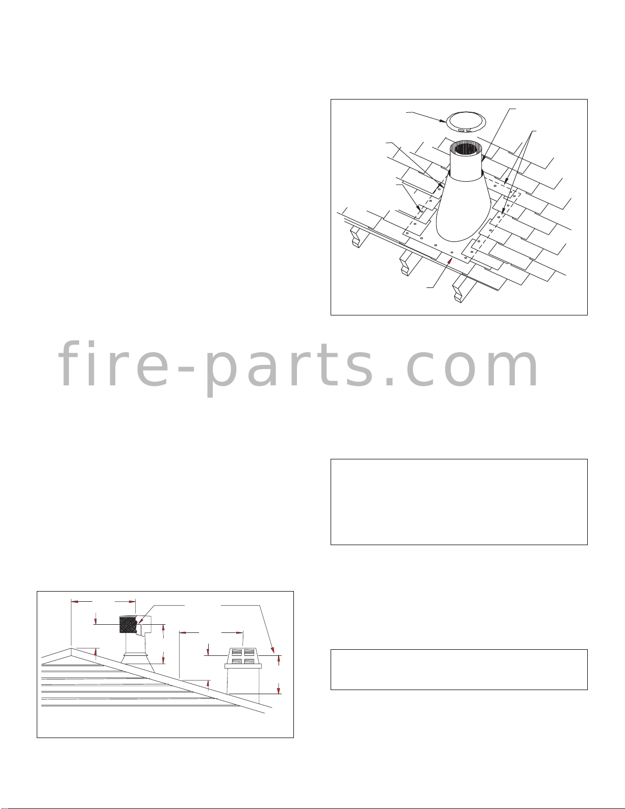
Figure 13
STORM
COLLAR
FLASHING
NAIL ONLY
OUTER
PERIMETER
OF FLASHING
UNDERLAP
SHINGLES
AT BOTTOM
OVERLAP
SHINGLES
TOP AND
SIDES ONLY
CHIMNEY PIPE
Figure 12
WITHIN 10'
(3.048m)
WITHIN 10'
(3.048m)
LEVEL OF FLUE
GAS OUTLET
2' MIN.
(609mm)
2' MIN.
(609mm)
3' MIN.
(914mm)
3' MIN.
(914mm)
NOTE: ANY OFFSET GREATER THAN 6 FEET MUST USE A
V12S-10DM.
PENETRATING THE ROOF
To maintain a 2-inch clearance to the pipe on a roof with a pitch, a
rectangular opening must be cut.
STEP 1: Determine the center point through which the pipe will
penetrate the roof.
STEP 3: From the center point determined in STEP 1, measure an
opening 20 inches wide (10 inches to each side of the center point).
For a roof pitch between 0/12 (flat) and 6/12, measure and opening
241/4inches long (121/4inches above and below). 12/12 to 18/12
pitches: Measure 30 inches (18 1/4above and below).
18/12 to 24/12 pitches: Measure 44 inches (22 above and below).
STEP4: Removetheshingles around theopeningmeasuredand cut
out this section.
STEP5: Addthenextsectionsofpipeuntiltheendpenetratetheroof
line. Check to see that proper clearance is maintained. Extend
chimney by adding sections of double wall pipe until pipe are a
minimumof30inchesabovehighestpointofroofcutout. Termina-
tionandchimneymustextendaminimumof36inchesabovehighest
point where it passes through roof (see 10-foot Rule and Figure 12).
TERMINATIONS
The firebox and chimney system must be vented to the out-of-doors
and must be terminated with the listed round top or chase termina-
tions. If a chase termination is desired, refer to the instructions
supplied with the termination.
FOR ROUND TOP TERMINATION
STEP 1: Slide the flashing over the pipe (no firestop is needed at the
rooflevel).Tacktheflashingdownatthetoptwocornerswithroofing
nails. Lay tiles over the top and sides of the flashing and secure them
to the roof through the flashing with roof nails. Lay tiles under the
lower edge and secure these to the roof. Mastic all nail heads.
STEP 2: Install storm collar on double wall chimney, apply water-
roof caulking around flashing top and push storm collar down
securely on sealer and flashing (see Figure. 13).
STEP3: Placetheroundterminationonto the pipe end as illustrated
and secure with the screws provided.
10 FOOT RULE
Allchimney terminationsmustextendaminimumof3feetinheight
abovethehighestpointwhereit passes through the roof andmustbe
atleast2feetabovethepeakoftheroofifwithinahorizontaldistance
of 10 feet from the peak (see Figure 12).
IMPORTANT: If an exposed portion of chimney is greater than 5
feet above the roof line, use support wires to keep chimney secured.
The support wires may be attached to the outer pipe of the chimney
with screws. Provided the screws are not long enough to penetrate
the inner flue pipe.
GAS LINE INSTALLATION
A gas line may be installed for the purpose of installing a gas appliance
available through your local distributor. Use only 1/2" black iron pipe
and appropriate fittings. When installing a gas line, a shut-off valve
designed for installation outside the firebox is recommended.
To install, remove the gas line plug located in side firebrick approx.
2" above the bottom. The plug must be tapped out from the finished
side towards the unfinished side (see Figure 14, page 7). Insert the
gaslineparalleltotheface. Fill anygapbetween thegasline andthe
hole in the firebrick with refractory cement or commercial furnace
cement (see Figure 15, page 7).
WARNING: All gas piping and connections must be
testedforleaksaftertheinstallationiscompleted. Be
suregasvalveisturnedon. Applysoapsudssolution
toallconnectionsandjoints. Ifbubblesappear,leaks
can be detected and corrected. DO NOT use a match
or open flame of any kind to test for leaks. Never
operate any appliance with leaky connections.
Thegaspipeisintendedforconnectiontoanunventedgaslogsetor
to a decorative gas appliance.
If you will install an unvented gas log set, ONLY UNVENTED GAS
LOG SETS WHICH HAVE BEEN FOUND TO COMPLY WITH
THESTANDARDFORUNVENTEDROOMHEATERS,ANS/IAS/
AGA Z21.11.2, ARE TO BE INSTALLED IN THIS FIREPLACE.
NOTE:An appropriate Vanguardhood must beinstalled when
using an unvented gas log set.
WARNING: DO NOT OPERATE AN UNVENTED GAS
LOG SET IN THIS FIREPLACE WITH THE CHIMNEY
REMOVED.
If you will install a decorative gas appliance, the decorative gas
appliance must comply with the Standard for Decorative Gas
Appliances for Installation in solid Fuel burning Fireplaces,
ANSZ21.60-1996andshallalsobe installed in accordancewiththe
National Fuel Gas code, ANS Z223.1-1996.
fire-parts.com


 Quick start guide")


 Specification sheet")