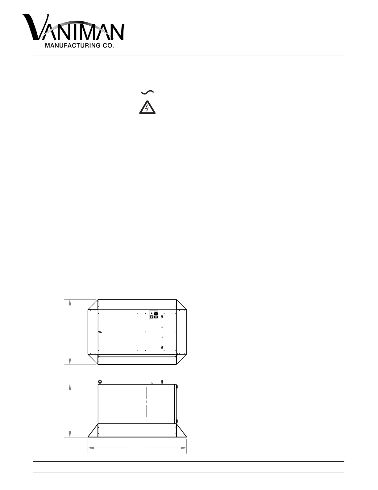
PURE BREEZE FUME HOOD
120V
25799 Jeerson
Ave.
Murrieta, CA
92562
1-800-V
ANIMAN (826-4626)
www.vaniman.com [email protected]10370-11/21 PAGE 5
Page 5
MAINTENANCE
Before performing any maintenance tasks on this unit, ip the On/Off switch into
the Off position and remove the supply cord from the unit.
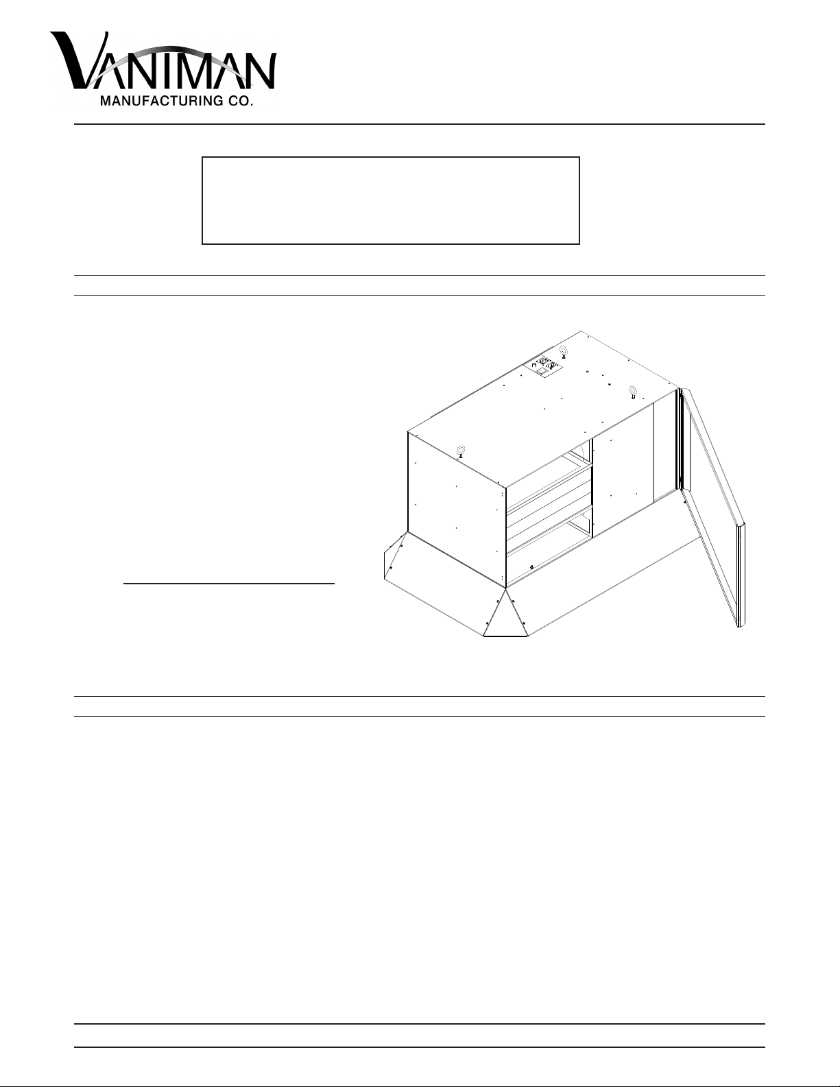
1. Filter Maintenance is most important to maintain a clean working environment. As dust, odors, and
microbes are collected from the air in the room, the lters start to ll. When lters are full, they restrict
air ow diminishing the eciency of the Fume Hood. Filters must be replaced regularly to assure the
proper function of this unit.
a. The Pre-lter (rst lter) is identied by its white media and is located on the very bottom of the
stack. This lter captures the majority of larger sized contaminates in the room and will need to be
changed more often than the other lters in the unit. Replace the Pre-lter when the air ow drops
signicantly, the lter appears substantially dirty, or every 3-6 months, which ever comes rst.
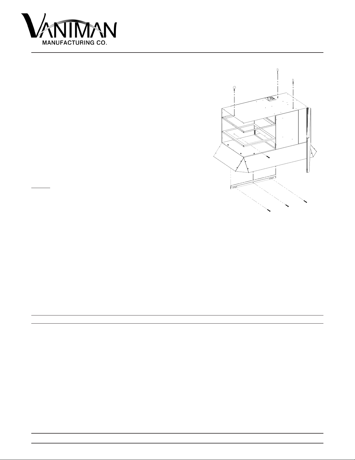
Replacing the Pre-lter:
You will notice a group of three lters; the Pre-lter is the one on the bottom. In order to change
the Pre-lter you must remove the two above it. Start removing lters from the top and work down
through the group of lters. When installing the new Pre-lter make sure the metal reinforcement
side is facing up. Inspect the other lters and replace them in the opposite order then they were
removed. Order P/N 97021.
b. The Secondary Filter is identied by its white media and is the second lter from the bottom in
the stack.This lter captures the smaller particles that may slip through the Pre-lter. As a rule, this
lter should be replaced once every three replacements of the Pre-lter.
Replacing the Second Filter:
Comparable to replacing the Pre-lter, you will need to remove the lter above rst, then remove
the Secondary lter. When installing the new Secondary lter, make sure the metal reinforcement
side is facing up. Order P/N 97022
For your convenience Vaniman oers a lter package which includes three Pre-lters and one
Secondary Filter. This lter package will enable you to replace your Pre-lters while reminding you
of the three to one lter maintenance schedule. Order P/N 97025.
c. The Charcoal Odor Filter (third lter) can be identied by its metal frame. The Charcoal Odor
Filter is located on top of the group of lters inside the unit. This lter absorbs odors in the air as it
is similiar to a chemical sponge used to collect odorous chemicals. The Charcoal Odor Filter must
be changed when an increase of odors from the unit is detected.
Repalcing the Charcoal Odor Filter:
Pull out the old Charcoal Odor lter from the unit. Remove the plastic packaging from the new lter
before sliding into place. Either side of the lter may face up. Vaniman recommends to always have
a spare, however, keep new unused lters wrapped in their plastic wrappers to ensure freshness
until use. Order P/N 97023.