Vantage Hearth DIN InFusion IC-DIN User manual

INSTALLATION
VANTAGECONTROLS.COM
1061 South 800 East • Orem, Utah 84097 • Telephone 801 229 2800 • Fax 801 224 0355 DIN InFusion Controller — MODEL: IC-DIN
Overview
The DIN InFusion™ Controller is part of the family of the most
powerful automation controllers on the market, featuring an
extremely fast processor, fast Bus communication, large
memory capacity, a built-in Ethernet jack and a USB port. Just
one DIN Infusion Controller supports up to 120 WireLink™
stations and up to 120 RadioLink™ stations. The DIN InFusion
Controller is the main “CPU” of Vantage’s most advanced
lighting System. It mounts to standard 35mm DIN rail. An LCD
interface provides immediate status and diagnostics. A Lithium
battery retains time and system status in a power outage. The
processor has real time and astronomical time clocks. Design
Center software is used to program the Controller. The
Controller runs independent of a PC after initial setup and
programming. Application code is upgradeable through Design
Center Software. InFusion Controllers operate as stand-alone
or networked. *The Vantage InFusion Controller Network can
consist of up to thirty-one Controllers in a single Network.
*15 Controllers maximum on each Controller to Controller Bus
run. Up to 31 Controllers are allowed when connected via
Ethernet.
Ethernet Port ●Standard USB Port ●Five Embedded RS-232
Ports ●Two RS-485 Ports ●Manual Override (front panel
buttons) ●Addressable (front panel buttons) ●Network
Termination Switch ●Reset Switch ●Built-in Protection ●
electrically isolated between controllers
DIN InFusion Controller Specifications
Dimensions HWD 86 x 157 x 58mm
Weight 417 g
Mounting 35 mm DIN Rail (EN 50 022: 1977)
Power Requirement 36VDC/5.5A or 24VDC/2.5A
Lightning / Surge Protection
Static Shock IO. All ports and case,
IEC 61000-4-2
Low Voltage, ITU-T K.20
Max. Length of Each Controller
to Controller Bus Network
2000 feet / 609 meters- using
16-18AWG 2-conductor, twisted pair,
non-shielded wire
Wiring config. C2C, IC Network Daisy Chain
Station Bus Specification
2C 16AWG, non-shield, <30pF per foot
Station Bus should be separated a
minimum of 18" from other parallel
communication and/or high voltage
runs.
Station Bus Power Supply with
200W/36VDC/5.5A source
One 60W independent power supply to
each station bus.
Station Bus Power Supply with
60W/24VDC 2.5A source
One 35W shared power supply to both
station buses.
Max. # WireLink Stations 36V
Up to 60 Stations each bus or until the
independent 60W supply is used on
each bus
Max. # WireLink Stations 24V Up to 50 Stations each bus or until the
shared 35W supply is used
Max. Wire Length Station Bus
2,000 feet of cabling max. on each
station bus. No station more than 1,000
feet from Controller.
Wire Configuration of Station
Bus Daisy Chain, Branch, Star
Ambient Operating
Temperature 0-40°C / 32-104°F
Ambient Operating Humidity 5-95% non-condensing
Cooling Convection
Lithium Battery Backup
Disk battery CR2032, 3Volt
2.5 yrs. un-powered or 30 yrs. powered
(field replaceable – See Caution at end)
*CAUTION: 36V stations have a symbol on the Serial
Number sticker. Any station, not displaying this symbol, should
not be connected to a 36Volt Station Bus.
Software/Firmware
Design Center Software must be used to program the
controller.
Design Center Software requires Windows XP.
Installation
Installation of Vantage products should be performed or
supervised by a Certified Vantage Installer. It is mounted on a
standard 35 mm DIN Rail in any standard DIN Enclosure. All
connections to the Controller are wired to removable screw
terminal connectors.
Powering The DIN Controller
The DIN Controller must be wired to a 200W, 36VDC or
24VDC power supply. Vantage can supply a DIN power
transformer part number #ACPDXXSM2. This power supply is
rated: Input, 120/230Vac, Output, DC 24V/2.5A and is DIN rail
mountable. Before using pull out the lithium battery tab
insulator on the DIN Controller. Connect the plus side of the
DC transformer to the 24V/36V screw terminal and the
negative side to one of the ground terminals. Connect another
wire from the second ground terminal to the enclosure ground,
earth ground.
NOTE: This earth grounding on the DIN Controller and power
supply should be the ONLY earth ground connection in this
DIN Controllers immediate system. Controller Bus (connections
between controllers) connections are isolated so a new earth
ground reference for each Controller is normal.
Controller Address
The DIN Controller’s address is no longer selected by adjusting
the turn dials for the correct address. The address is now
assigned through the front panel buttons on the DIN
Controller.
Follow these steps to set the Controller Address:
•With the Controller on screen 1 (HOME), press any
button on the front of the Controller
•Press the 4th button under “C2C”
•Press the second button under “Next” until the cursor is
at the Controller number, “C#” for 10s place and again
for 1s place.
•Press the button under “Adj” until the address is correct.
Valid addresses are from 01 to 31.
•Press the button under “Set” to save the setting
•The DIN Controller will reboot with the new address on
screen 1 (HOME) as shown below
InFusion DIN Controller Setup in Design Center
Every new project in Design Center automatically includes an
InFusion Controller. Change the Controller to IC-DIN at the
beginning of the project, and select if it will have a 36VDC or
24VDC power supply. Design Center 2.3 and higher allows a
DIN controller to be setup as default under Settings | System
Preferences | Default Controller Type. Additional controllers
are added automatically as the project grows, however it is
possible to add additional Controllers at any time. Remember
to select the proper Controller, i.e., IC-DIN, IC-36V or IC-
24V.

Programming the InFusion Controller
All programming is created in InFusion Design Center
software. Projects should be saved regularly when being
created. They may be edited at any time in Design Center and
resaved (preferably under a new name). Design Center
projects may also be saved to MMC/SD flash memory cards.
The card can then be placed into the card slot reader in the
front of the InFusion Controller to program the IC (see Front
Buttons below). Design Center projects may be downloaded to
the IC via Ethernet or USB.
Memory Card
An MMC/SD flash card slot is provided for program backup.
•Stores all programming for project file
•Stores graphic rich web interface (future feature)
•Can be read and written directly using Design Center
Diagnostics.
•InFusion System (all Controllers) may be
programmed/re-programmed from the flash card
connected to any Controller without running Design
Center or connecting a computer.
•Only one flash card is needed and only one is
recommended per system
•See Design Center software Help for details
Controller Bus to Controller Bus Wiring
When connecting multiple Main Enclosures, Vantage
recommends the use of 16-18 AWG 2-conductor, twisted pair,
non-shielded wire from IC to IC. This is a polarized connection
with “+” and “–“ screw terminals for two runs of wire. The
beginning and ending Main Enclosures will use one set of
screw terminals at the Controller Bus terminals and all Main
Enclosures in-between will use both sets of screw terminals on
the Controller Bus terminals, i.e., one set of screws connecting
from the previous enclosure and the other set of screws
continuing to the next enclosure. The maximum wire length for
all Controllers connected together on one bus should not
exceed 2,000ft. using the above wire specification.
Controller to Controller Ethernet Wiring
InFusion Controllers may also be connected using the Ethernet
ports on the front of each Controller. When this is done a
cross-over network cable must be used from controller to
controller. The maximum length of a crossover network cable
is 328ft or 100meters. C2C, Ethernet connection must be
Enabled – see InFusion Controller Front Panel Button
Operation (below).
Controllers may also be connected using a standard network
cable to a router or hub. With this type of connection it may be
necessary to assign unique Channels from IC’s front panel, in
case more than one InFusion Design Center System is on a
network. With this type of connection InFusion network
distances are only limited to the network itself.
Controller Terminator Switch
If only one DIN InFusion Controller is used, the Controller
Network Termination switch should be ON. This switch is
located on the front/top side of the Controller. If multiple
Controllers are used ONLY the first and last Controller on each
Controller Network Bus should have the Controller Network
Termination switch ON.
Example 1: In a five Controller system, Controllers 1 and 5 are
not necessarily the first and last Controllers, i.e., the “wiring”
order could be 2-1-3-5-4. In this example, Controllers 2 and 4
are the first and last Controllers in the network, so only these
two would have the Controller Network Termination switch
ON, the other three must be OFF.
Example 2: In a ten Controller system, let’s say enclosures 1
through 5 are connected through one Controller Bus and
enclosures 6 through 10 are connected through another
Controller Bus. Each of these independent Controller Buses
could have up to 2,000ft of cabling. Controllers 5 and 6 are
connected through Ethernet. In this example enclosures 1 and
5 are terminated for the first Controller Bus and enclosures 6
and 10 are terminated for the second Controller Bus. This is
because they are two independent Controller Bus networks,
connected together with one Ethernet connection. This
scenario may be repeated multiple times in various
configurations up to 31 Controllers maximum on one system.
Auxiliary Power
On the bottom of the IC-DIN are connectors for a 12VDC
auxiliary power connection. Connect the common to any GND
on the bottom of the Controller. The 12VDC connection is
typically used for one RF Enabler. Total power is limited to
250ma. NOTE: If an additional RF Enabler is connected to the
DIN Controller, it must be powered externally.
RS-232 Connections
The IC-DIN has five RS-232 ports. These ports may be used to
connect any device that uses RS-232 communication. Any
compatible RS-232 device may be connected, however, only
one device should be connected at a time to any RS-232 port.
The default protocol may be changed through Design Center
software.
Most devices typically use RX, TX and GND for communication.
In the event that an RS-232 device requires RTS and CTS use
Port 1 or Port 2. RS-232 Ports 3-5 only have TX, RX and GND.
All five ports can use software flow control.
Communication protocol settings:
•Standard baud rates 1200 – 115.2K
•7-8 Data Bits
•Even, Odd, Forced or No Parity
•100ft. maximum wiring distance
RS-485 Connections
On the top connector of the IC-DIN are two RS-485 ports. The
RS-485 ports are half-duplex, meaning that each port can
transmit and receive but not at the same time. Maximum wiring
distance for RS-485 ports is 200ft.
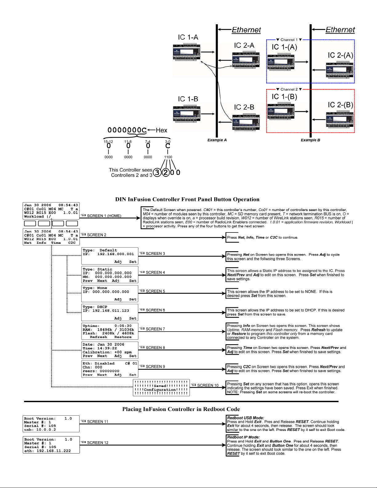
Front Buttons
Through the front panel buttons on the DIN InFusion
Controller, Time, Connection protocol, IC Information,
Controller Address and other settings may be edited. The
Controller may also be placed in boot (Redboot) mode from
the front controls. The following contains detailed information
for some of the LCD screens shown below:
SCREEN 4 – A static IP address may be assigned to the IC.
Once a static IP address has been assigned to the Controller
and saved, the NM: (NetMask) address displays automatically.
A typical NetMask would be 255.255.255.000. With the
NetMask field highlighted click the Adj. button to change to
GW/GateWay, and adjust the Gateway address.
SCREEN 6 – This screen allows the InFusion Controller to
obtain an IP address automatically through DHCP. Record this
address in the Design Center project file for future connections
through Ethernet.
SCREEN 7 – This screen shows information about the IC.
•Uptime – the amount of time the IC has been operating
without loosing power, reported in days:hours:minutes.
•RAM – Free Memory / Total Memory
oRAM is like the RAM on a computer. This is the active
memory, Random Access Memory and is volatile,
meaning when power is lost to the Controller, this
memory is cleared.

•Flash – Free Memory / Total Memory
oFlash memory is like the Hard-Drive on a computer.
This is the main memory storage area for all
programming. Data is compressed when downloaded.
•Refresh – updates (live) this screen, buttons 1 or 2.
•Restore – If any IC on a system contains a flash memory
card, pressing button 3 or 4 will cause the program on the
card to be loaded to this InFusion Controller only.
SCREEN 9 – This screen is very important when using IP for
controller to controller communication. C2C | Ethernet: (Eth:)
must be Enabled (default) using this mode.
Channel: Because more than one InFusion System may be on a
single network a channel (Chn:) number may also be assigned.
Example, it is possible to have two ICs with address 1 in a large
building containing two or more InFusion systems and one
network. Assigning a unique channel number to each
Controller allows the
identically addressed
controllers to operate as
independent systems on the
same network.
Peers: This is a bitmask of all
controllers visible to this
controller displayed in HEX.
Convert to binary to see
controllers position. Each “1” in binary, is a Controller.
Example: Peers:
SCREEN 9 (cont.) –
Channels:
In Example A above, “IC 1-A” sees both “IC 2-A” and “IC 2-B”
controllers. It does not know which IC 2 belongs to it’s
network.
In Example B above “IC 1-A” and “IC 2-A” have been assigned
to Channel 1 and “IC 1-B” and “IC 2-B” have been assigned to
Channel 2. This now allows each controller on the network to
only talk to its co-controllers and ignore other controllers.

Remote Access Port Settings
In order to access the InFusion Controller outside the home
network (for remote programming), you will need to forward
internet ports 2001 and 3001 from the router or modem, that is
connected to the internet, to the IP address of the InFusion
Controller. If using a static IP address on the controller you will
need to set the gateway. To set the Gateway, navigate to the
Static IP address screen on the front of the controller. With the
NetMask (NM:) field highlighted click the Adj. button to change
to Gateway (GW), and adjust the Gateway address (also see
Screen 4 explanation above).
Make sure that you are allowing the Ping operation as this is
used by InFusion to verify its connection.
At your remote location, enter in the IP Address, assigned from
the ISP, of the router or modem into Design Center to connect.
If you are unsure how to do this you may need to contact an IT
professional to set it up for you.
Possible Ground Loop Issues
All RS-232/RS-485 connections between third party equipment and RS-232/RS-485 connections on the DIN Controller, may produce
a ground loop. Often the third party connected RS-232/RS-485 device is not using the same power source or is far away from the
DIN Controller resulting in a possible ground loop or data noise condition. If this condition is suspected, Vantage recommends a third
party RS-232/RS-485 Opto (optical) Isolation Module. Opto Isolation provides a communications link and is an important
consideration if a system uses different power sources, has noisy signals or must operate at different ground potentials.
39972 / InFusion Warranty at: http://www.vantagecontrols.com/warrant
y
©Vantage
Other Vantage Hearth Controllers manuals