Vantage Hearth InFusion IC-DIN-II User manual

©Vantage, 8/17/2016 / IS-0600-B DIN InFusion Controller II — MODEL: IC-DIN-II page 1 of 7
INSTALLATION
VANTAGECONTROLS.COM VANTAGE INSTALL GUIDES
2168 West Grove Parkway, Suite 300, Pleasant Grove, UT. 84062 USA
Telephone: 801 229-2800 ●Fax: 801 224-0355 DIN InFusion Controller II — MODEL: IC-DIN-II
Overview
The InFusion™ IC-DIN-II is Vantage’s most
powerful automation controller to date,
featuring a new, extremely fast processor
improving processing performance.
Systems using the previous InFusion DIN
controller may be upgraded by simply
installing the new controller,*converting
the project file in Design Center 3.3 or higher, and downloading to
the new controller.
*See Replacing and/or Upgrading InFusion Controllers for
additional information.
Features
The InFusion Controller is the main “CPU” of Vantage’s
complete systems integration solution
Automatic crossover support, RJ45 Ethernet connection.
Secure access – password protected
Design Center connection through local network or offsite
oFirmware updates and full or minor program changes
Automatically restores previous firmware and
program code if update fails
oDiagnostics
oRead system
oProject control
Built-in Ethernet jack
Type-A, USB port (future features ready)
oThe USB port is not used on IC-DIN-II controllers to
program from Design Center as in previous InFusion
controller models
Micro SD card support (included)
Automatic System Backups to micro SD card
oManually through front panel – real time
oWithin 24 hours of programming system
-then-
oWeekly
oUp to 52 backups total
oOldest backup is replaced when 52 limit is reached
oBackups may be used to program system controllers
Restore entire system from System Backups
oUndo option from last Restore
Ram and Flash memory
One controller supports up to 120 WireLink™ stations and up to
120 RadioLink™ stations
Local LCD interface provides limited control, status and
diagnostics
Lithium battery retains time and system status in a power
outage
Maintains real and astronomical time clocks
Design Center software is used to program the Controller
The Controller runs independent of a PC after initial setup and
programming
Application code is upgradeable through Design Center
software
InFusion Controllers operate as stand-alone or networked
Five RS-232 Ports
Two RS-485 Ports (shared with SE buses 3 and 4; simultaneous
RS-485 and SE bus connections are not possible)
Manual Override Switch
Reset Switch
Built-in Protection, electronic isolation between controllers
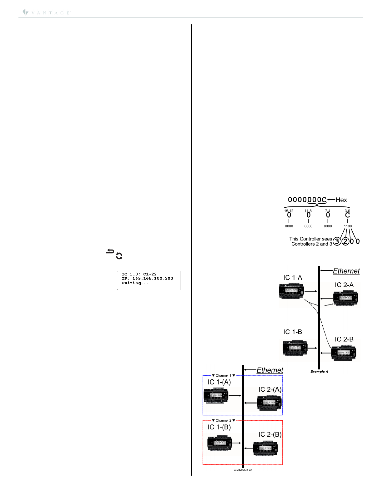
*The Vantage InFusion Controller Network can have up to
thirty-one Controllers when connected via Ethernet
*15 Controllers maximum on each Controller to Controller
Bus run.
InFusion Controller Specifications
Description Specification
Dimensions HWD 85.7mm x 157.2mm x 61.9mm
3.38” x 6.19” x 2.44”
Weight 417 g / 0.92 lb.
Mounting 35 mm DIN Rail (EN 50 022: 1977)
Power Requirement 36VDC/3.6A or 24VDC/2.5A
Description Specification
Power Supplies
PSU36-DIN – 130W, 36VDC
ACPDXXSM2 – 60W, 24VDC
DIN POWER-MC – 96W, 24VDC, Europe
Lightning / Surge
Protection Static Shock
IO. All ports/case
IEC 61000-4-2
Low Voltage, ITU-T K.20
Bus Network
Max. Length of Combined
IC-II to IC-II
2000ft / 609m- using 16-18AWG
/ 1.31-0.75mm2, 2-conductor, twisted pair,
non-shielded wire
C2C, IC Network Ethernet (see Screen 16, p. 3)
Station Bus Specification
2C, 16AWG / 1.31mm2, twisted, non-shielded,
<30pF per foot. Separate a minimum of 12" /
30.5cm from other parallel communication
and/or high voltage runs.
Station Bus Power
Supply, IC-36-1
Each station bus run has a 60W power supply;
Station Bus Run 1 = 60W
Station Bus Run 2 = 60W
Station Bus Power
Supply, IC-24-1
Shared, 35W max. power supply combined to
both station bus runs.
Max. Wire Length Station
Bus
609m / 2,000ft of cabling max. on each
station bus. No station more than 305m /
1,000ft from Controller.
Wire Configuration of
Station Bus
Daisy Chain, Branch, Star
(contact support for
Station Bus Best Practices)
Max. # WireLink Stations
IC-36V
Up to 60 Stations each bus or until the 60W
supply per bus is used
Max. # WireLink Stations
IC-24V
Up to 50 Stations each bus o
r
until the
shared 35W supply is used
Cooling Convection
Lithium Battery Backup
Disk battery CR2032, 3Volt
2.5 yrs. un-powered or 20 yrs. powered (field
replaceable – see Caution at end)
Ambient Operating
Temperature 0-40°C / 32-104°F
Ambient Operating
Humidity 5-95% non-condensing
UL/cUL/CE/FCC Certified YES
Software/Firmware/Installation Requirements
Installation of Vantage products should be performed or
supervised by a Certified Vantage Installer. Design Center
Software, version 3.3.X.X or higher must be used to program
controller models with the “-II”. Using IC-1 and IC-II controller
models on the same system, is not supported. Disconnect power
when plugging in or un-plugging the controller’s power connector.
Use a dedicated breaker to power the controller. Multiple InFusion
Controllers may share the same breaker when in close proximity.
Powering the DIN Controller
The DIN Controller must be wired to Vantage’s PSU36-DIN 130W,
36VDC or ACPDXXSM2 60W, 24VDC power supply. Power
supplies must be mounted to 35mm DIN rail in any standard DIN
Enclosure compatible with the maximum power dissipated. Before
using pull out the lithium battery tab insulator on the DIN
Controller. Connect the positive (+) output of the power supply to
the 24V/36V screw terminal and the negative side to one of the
ground terminals. The Controller and Power Supply must be earth
grounded. Carefully follow the Wiring Diagrams below. DO NOT
USE ANY OTHER POWER SUPPLY*.
*NOTE: Another (Vantage Certified) 96W, 24VDC power supply,
DIN POWER-MC, is also available in the European region from
Vantage EMEA; visit, www.vantage-emea.com.
NOTE: The earth ground on the DIN Controller and power supply
should be the ONLY earth ground connection in this DIN
Controller’s immediate system. Controller Bus (connections
between controllers) connections are isolated so a new earth
ground reference for each Controller is normal.
Vantage recommends a minimum 0.75mm2/ 18AWG wire,
stranded, between the power supply and the controller.
Recommended: keep wires no longer than 1 meter between
the power supply and the controller.

I N S T A L L A T I O N
©Vantage, 8/17/2016 / IS-0600-B DIN InFusion Controller II — MODEL: IC-DIN-II page 2 of 7
Controller Address
The DIN Controller’s address is assigned through the front panel
buttons on the DIN Controller.
Follow these steps to set the Controller Address:
With the Controller on screen 1 (HOME), press any button on
the front of the Controller
Press the 4th button under “C2C”
Press the second button under “Next” until the cursor is at
the Controller number, “C#” for 10s place and again for 1s
place.
Press the button under “Adj” until the address is correct.
Valid addresses are from 01 to 31.
Press the button under “Set” to save the setting
The DIN Controller will reboot with the new address
Make sure Design Center has the same controller address
InFusion Controller Setup in Design Center
Every new project in Design Center automatically includes an
InFusion Controller. Additional controllers are added as the project
grows, however it is possible to add additional Controllers at any
time.
Replacing and/or Upgrading InFusion Controllers
See IMPORTANT: Steps Upgrading Equinox Systems before
completing these steps. To convert an existing project from IC-1 to
IC-II controllers, open the file in Design Center 3.3*or higher and
follow these steps:
1. Select Enclosure View and right click on the first controller
and select Convert to Second Generation Controller.
2. The message box is opened explaining that all controllers will
be converted. Answer OK.
3. All of the controllers are then converted to generation II
controllers with original programming.
*IMPORTANT: Steps Upgrading Equinox Systems
Projects with Equinox devices should do the following.
1) Program the system one more time with the old project file
before replacing the controllers, (assuming the old controllers
will accept programming from Design Center). Be sure Read
and Restore, Equinox Profiles and User Data is checked.
Move to new Controllers
2) With the newly converted file opened in Design Center, click on
System | Backup and Restore | Restore Equinox Data From
Backup,
3) Select the most recent *.EQUD file; answer yes to the question
below.
4) Design Center will program the system with the new file and
restore Equinox data to new controllers stored in the *.EQUD
file.
Programming the InFusion Controller
Programming is created and edited in Design Center software and
saved as a project file. Projects are then downloaded to the system
controllers via a local or remote connection to the local network. It
is recommended to have one micro SD flash card per system and
that the micro SD card be placed in the same controller used to
connect Design Center (faster).
Program Controller Using A Direct Connection From Computer
If the controller is not connected to the local network, it is possible
to program the controller by connecting the computer directly to
the controller via an Ethernet cable – standard or cross-over type.
Set the controller IP address to the Default setting,
192.168.0.<controller number>
Set the computer’s IP address to 192.168.0.40 or similar
(USB connection between Design Center and IC-II controllers is not
supported.)
Ethernet Port Settings
In Design Center select either a standard or secure (SSL)
Ethernet connection.
If using Secure Ethernet protocol, Secure Sockets Layer (SSL),
recommended, Design Center checks a security certificate
against a security certificate stored on the controller. If they do
not match a warning is displayed.
It is recommended to double check the IP address of the
controller. If the IP address is correct, change the connection to
standard Ethernet and re-download the controller firmware. This
procedure will also require the system to be re-programmed
after the firmware update. Updating all controllers firmware
shipped with Design Center 3.3, or higher, should clear this error
for future SSL connections, unless a certification problem exists.
Remote Programming and Maintenance
Remote programming and update capability may save unnecessary
trips to actual sites. With remote updates, care should be taken to
ensure that updates are complete and the system’s new
programming functions properly.
Remote Access Ethernet Port Settings
For standard Ethernet connections, forward ports 2001 and 3001
to the IP address of the InFusion Controller.
For Secure Ethernet connections (SSL), forward ports 2010 and
3010 to the IP address of the InFusion Controller.
When using a static IP address on the controller the gateway
must also be setup on the controller.
Allow the Ping operation – used by Design Center to verify its
connection.
In Design Center enter the IP Address of the router or modem
assigned from the ISP. Design Center may also require a User
Name and Password if security has been enabled.
Backup Memory Via Micro SD Card
A micro SD flash card slot is provided for program backup and
allows automatic backups periodically performed by the controller.
Stores backup of all programming for project file.
Stores graphic rich web interface (i.e., WebPoint Lite).
SD cards directly accessed using Design Center Diagnostics.
InFusion System (all Controllers) may be programmed/re-
programmed from the micro SD card connected to any
Controller without running Design Center or connecting a
computer.
Typically, only one micro SD card is recommended per
system.
Replace the existing micro SD card when inserting an Equinox
multiple license micro SD card.
Controller to Controller Wiring
C2C Ethernet Bus
Today’s integrated devices use ever increasing amounts of
metadata. For this reason it is recommended to use C2C Ethernet
communication between multiple controller systems. Each
controller should have its own Ethernet connection to the local
Notice different icons (left) old (right) new.
Use same process to convert back to first
generation controllers.

I N S T A L L A T I O N
©Vantage, 8/17/2016 / IS-0600-B DIN InFusion Controller II — MODEL: IC-DIN-II page 3 of 7
Example B:
The “A” controllers and the
“B” controllers have been
assigned channel numbers
1and 2respectively:
Channel 1 for IC 1-A
and IC 2-A.
Channel 2 for IC 1-B
and IC 2-B.
This now allows each
controller on the network
to only talk to its co-
controllers and ignore
other controllers.
Example A:
IC 1-A sees both IC 2-A and
IC 2-B controllers. It does
not know which IC 2 belongs
to its network. At the same
time IC 1-B also has the
same problem.
network. In turn the local network should have access to the
internet. With this type of connection it may be necessary to assign
unique Channels from the IC’s front panel, in case more than one
InFusion Design Center System is on a network (See Front Buttons
| Screen 16 later in this document). With this type of connection
InFusion network distances are only limited to the network itself.
C2C Ethernet connection must be Enabled.
Controller Bus
When connecting multiple controllers via Controller Bus, Vantage
recommends the use of 16-18 AWG 2-conductor, twisted pair, non-
shielded wire from IC to IC. This is a polarized connection with “+”
and “–“ screw terminals. The maximum wire length sum for all
controllers connected together may be up to 2,000ft. using the
above wire specification.
Main Enclosure Terminal Board – Terminator Switch
If one or two InFusion Controller are used, the Controller Bus
Termination switch is always ON. This switch is located on the Main
Enclosure Terminal Board. If more than two Main Enclosures are
used ONLY the first and last Main Enclosure Terminal Boards on
each Bus should have the Controller Bus Termination switch ON.
NOTE: Termination switch has no affect on C2C communication.
When updating an existing Vantage system to generation II
controllers the existing Controller Bus may be left. However, if
possible, run Ethernet to each controller on the updated system
and enable C2C Ethernet Bus communication. The new controllers
will use the C2C connection as primary and use the Controller Bus
as a backup.
For additional Enclosure wiring information, please see:
Enclosure Instructions (click to open).
Front Buttons
Through front panel buttons on the InFusion Controller edit or see,
time, IP connection, IC Information and other settings. The
Controller may be placed in service mode from the front controls.
Service Mode:
Press and hold the EXIT button.
Press and release the RESET button.
Continue holding EXIT for about 5 seconds, then release.
Press RESET by itself to exit
service mode.
Service Mode Screen should
appear
similar:
SCREEN 4, IP SETTINGS – A static IP address may be assigned to
the IC. Once a static IP address has been assigned to the Controller
and saved, the NM: (NetMask) address displays automatically. With
the NetMask field highlighted click the Adj. button to change
settings for NM, GW, DNS1, and DNS2. Adjust each communication
protocol as needed. The NM and GW settings are necessary for the
controller’s internet access and the connection of remote Equinox
devices.
SCREEN 6, DHCP – This screen allows the InFusion Controller to
obtain an IP address automatically through DHCP. Record this
address in the Design Center project file for future connections
through Ethernet.
SCREEN 7, CONTROLLER INFORMATION – This screen shows
information about the IC.
Uptime – the amount of time the IC has been operating without
losing power, reported in days:hours:minutes.
RAM – Free Memory / Total Memory
oRAM: This is the active memory, Random Access Memory
and is volatile.
●Flash – Free Memory / Total Memory
oFlash memory is nonvolatile like the Hard-Drive on a
computer. This is the main memory storage area for all
programming. Data is compressed when downloaded.
Backup – System must contain a micro SD card to create a
current backup of the system via the micro SD card. Answer
Yes or No to create or cancel the new backup.
Restore*– System must contain a micro SD card. Pressing
button 3 or 4 will open a screen allowing the selection from a
history of backups. Select which backup is wanted with
Up/Down buttons and then press Select. Answer Yes or No to
execute or abort the restore.
*This will re-program all of the controllers on the system from
the selected backup. When a backup has been manually
executed an Undo option appears in the backup history list.
SCREEN 16, C2C SETTINGS – This screen is very important when
using IP for controller to controller communication. C2C— Ethernet:
(Eth:) must be Enabled.
Channel: Because more than one InFusion System may be on a
single network a unique channel (Chn:) number may be assigned to
the controllers for each InFusion System. The Peer number is
assigned automatically.
Example, it is possible to have two or more ICs with address 1,
address 2, and etc., in a large building containing two or more
InFusion systems. These InFusion systems can all be on one
network. Assigning a unique
channel number to each
Controller group allows the
identically addressed
controllers to operate as
independent systems on the
same network.
Peers: This is a bitmask of all
controllers visible to this
controller displayed in HEX. Convert to binary to see controllers
position. Each “1” in binary, is a Controller.
Example: Peers:
Channels: –

I N S T A L L A T I O N
©Vantage, 8/17/2016 / IS-0600-B DIN InFusion Controller II — MODEL: IC-DIN-II page 4 of 7

I N S T A L L A T I O N
©Vantage, 8/17/2016 / IS-0600-B DIN InFusion Controller II — MODEL: IC-DIN-II page 5 of 7
New Controller Features in Design Center 3.3
Design Center 3.3 is compatible with IC-1 and IC-II generation
controllers. Many of the new 3.3 features are available in both
versions of the InFusion Controller.
New Features
Security
Backup and Restore
Enhanced Email Support
Remote Location Firmware Updater – IC-II models only
SECURITY
Security Levels and Users Table
Security
Levels
Level Requirements For Groups
Admin User
None No credentials required
from any connection
No credentials required
from any connection
Remote
Credentials required for all
remote connections
including Design Center
Credentials required for
all remote connections
using Host Commands
Connections from Design
Center; not allowed
Local
Credentials required for all
local or remote
connections including
Design Center
Credentials required for
all local or remote
connections using Host
Commands
Connections from Design
Center; not allowed
Setting Up Controller/Project Security
1. By default project security will be
OFF when a new project is
started.
2. To turn on project security in a
new or existing project, click on
Settings and select Project
Security. The Project Security
Dialog opens.
3. Initially the Security Level is set to None and no Users and
Devices exist. If the security level is changed to Local or
Remote, at least one Admin user must be added before exiting
the dialog box.
4. To create a user press Add
User. The Add New User dialog
box opens.
5. Enter a Username and
Password and select Admin or
User to assign a group.
6. Press Add to add the new user.
a. Admin, have all
permissions selected by
default. Admin is required
by Design Center with
security enabled.
b. Users, cannot connect to the controller from Design
Center. Users only have Read State and Write State
permissions using Host Commands.
i. Custom permissions may be selected for either
group member type.
7. The Remote security level requires proper credentials for any
remote connection.
8. The Local security level requires proper credentials for local or
remote connections – highest security level.
9. The security setting is sent to the controller when
programming or updating the system.
10. All security settings are saved with the project.
Exceptions to Security
1. IP Address Exception List
a. If a third party device is not capable of sending a
username/password, the IP Address of that device can
be entered into the exception list. This excludes the
device at that IP Address from security settings.
2. Serial Port Exception
a. If a third party device connected to a serial port is
unable to send a username/password, check the
Exclude from Security checkbox in Object Editor. This
excludes the device from the security settings.

I N S T A L L A T I O N
©Vantage, 8/17/2016 / IS-0600-B DIN InFusion Controller II — MODEL: IC-DIN-II page 6 of 7
Connecting Design Center With Security Enabled
1. If the Security Level is set
to None, connecting to
controller proceeds
normally.
2. If the Security Level is set
to Remote, local
connections proceed
normally while remote
connections require
proper credentials.
3. With security enabled Design Center prompts for a user name
and password.
a. Entering an Incorrect user
name and/or password results
in an Invalid Credentials
message.
4. If authentication is accepted, the
username and password are not
required again while the project is open and the IP address
remains the same.
Ethernet Connection
5. The dealer will be allowed to choose if they want a secure
connection or an unsecured connection. For remote
connections forward ports to the IP address of the InFusion
Controller.
a. Secured ports (SSL) are: 2010, 3010
b. Standard ports are: 2001 and 3001
Temporary Security Override
1. A Security override feature exists on the controller through
the panel buttons on the front of the Controller.
a. From controller press Exit until the
controller is back to screen 1, the
Home page. From the Home page
press and hold Exit for about 6
seconds – until the screen changes.
b. Press Adj to change security setting to None or Remote.
Press Set to commit change. The change will be active
until system is reprogrammed. Pressing the Exit button
without making changes cancels the controller screen
without saving changes.
c. NOTE: If security has not already been programmed on
the controller from Design Center, adjusting the security
setting via the controller buttons does not do anything.
BACKUP AND RESTORE
Using backup and restore
The backup and restore feature requires that one or more
controllers on the system contain an SD Card.
Recommendation: The Controller used to connect Design
Center contains the system’s SD card.
Recommendation: Install one SD card per system.
Backup and Restore From Design Center
1. In Design Center click on System | Backup And Restore and
select from:
a. Full System Backup
b. Full System Restore
c. Restore Equinox Data From Backup.
i. Option “c”, restores Equinox profile information on
controller and opens programming screen.
2. If Backup is selected the system writes the current controller
programming to the sd card.
3. If Restore is selected the system opens a selection menu.
a. Last Week
b. Last Month
c. Last Quarter
d. User Initiated (only
shows when a
manual backup
operation has been
selected)
e. Choose Backup by Date
4. Choose Backup by Date opens a complete history.
5. These same operations may be performed from the controller
via the front panel buttons. See InFusion Controller Front
Panel Button Operation (above).
ENHANCED EMAIL
Expanded Email Options
1. Design Center 3.3 comes with new controller firmware
containing enhanced email support.
a. Gmail c. Outlook.com
b. Yahoo d. Etc.
NOTE: IC-1 and IC-II models could differ in email support – IC-1
has a smaller OpenSSL library do to memory restrictions. Test
to verify email operation on all
email services.
2. In Design Center click on Settings
and select Project Information.
3. In the Project Information window, select the Email tab to
open the email setup window.
4. The Server Address is the SMTP server information, for
example, smtp.gmail.com. The correct SMTP server
information is needed for the Email service being used. Please
check with the email service provider for the specific SMTP
Server information.
5. The User Name is the user name used when setting up an
6. Finally the Password is the password required to access your
email account.
7. Click OK when finished.
8. Tasks may be assigned to send emails as part of their
execution process. NOTE: Email setup in any Design Center
project helps the project be future ready for new features.
9. In Design Center select Communication | Messaging | Send
Email.

I N S T A L L A T I O N
©Vantage, 8/17/2016 / IS-0600-B DIN InFusion Controller II — MODEL: IC-DIN-II page 7 of 7
!
CAUTION, BATTERY MAY EXPLODE IF
MISTREATED. DO NOT RECHARGE, DISASSEMBLE,
OR DISPOSE OF IN FIRE. REPLACE ONLY WITH THE
SAME OR EQUIVALENT TYPE RECOMMENDED BY
THE MANUFACTURER. DISPOSE OF USED
BATTERIES ACCORDING TO THE MANUFACTURE’S
INSTRUCTIONS.
Lithium Battery CR2032, 3Volt
(remove tab before using first time)
InFusion IC-DIN-II Power Supplies
Wiring Diagrams
Only use Power supplies shown here. PSU36
Dimensions, HWD: 3.85” x 9.6” x 1.7” / 98mm x
244mm x 44mm *The PSU36-DIN may be
ordered with an optional, trim finishing plate.
Important:
The PSU36-DIN or ACPDXXSM2 power supplies,
must be mounted on a standard 35 mm DIN Rail
in any standard DIN Enclosure compatible with
the maximum power dissipated
*NOTE: Another (Vantage Certified) 96W,
24VDC power supply, DIN POWER-MC, is also
available in the European region from Vantage
EMEA; visit, www.vantage-emea.com.
ACPDXXSM2 Dimensions, HWD:
3.38” x 2.75” x 2.28”
86mm x 70mm x 58mm
Related DIN Products
DIN_8 Channel 10 Amp Relay Station_RS8-DIN_install_IS-0587
DIN_Controller Power Supply_PSU36-DIN_ACPDXXSM2_install_IS-0491
DIN_Electronic Load Dimmer Station_ELDS4-1-DIN_install_IS-0484
DIN_InFusion Controller II_IC-DIN-II_install_IS-0600
DIN_Lite Controller DIN_install_IC-DIN-LITE_IS-00617
DIN_Lite Controller DIN_install_IC-DIN-II-LITE_IS-00617
DIN_Low Voltage Output Station_LVOS-0-10-PWM-DIN_install_IS-0521
DIN_Relay Station Lighting_RS8-L-DIN_install_IS-0509
DIN_Standard Load Dimmer Station_SLDS4-DIN_install_IS-0588
DIN_Universal Load Dimmer Station_ULDS1-DIN_install_IS-0465
DIN_WireLink and RadioLink CIS_CIS10-DIN_STIDER121_install_IS-0584
DIN_WireLink and RadioLink LVRS_LVRS8-DIN & STOLER821_install_IS-0585
Possible Ground Loop Issues
All RS-232/RS-485 connections between third party equipment and RS-232/RS-485 connections on the DIN Controller, may produce a ground
loop. Often the third party connected RS-232/RS-485 device is not using the same power source or is far away from the DIN Controller resulting
in a possible ground loop or data noise condition. If this condition is suspected, Vantage recommends a third party RS-232/RS-485 Opto
(optical) Isolation Module. Opto Isolation provides a communications link and is an important consideration if a system uses different power
sources, has noisy signals or must operate at different ground potentials.
Table of contents
Other Vantage Hearth Controllers manuals
Popular Controllers manuals by other brands

Kramer
Kramer RC-2C user manual

Bray Controls
Bray Controls 92 Series Technical manual

J&E Hall
J&E Hall Fridgewatch 2100 Installation, operating and maintenance manual

Carrier
Carrier i-Vu MPC Open XP IO48/816 Installation and startup guide

Open House
Open House H571 user guide

Resistron
Resistron ROPEX RES-409 operating instructions