Varian 969-9860 User manual

Hand-held Terminal


ISTRUZIONI PER L’USO .................................................................................................... 1
GEBRAUCHSANLEITUNG ................................................................................................. 2
MODE D’EMPLOI................................................................................................................ 3
INSTRUCTIONS FOR USE ................................................................................................ 4
TECHNICAL INFORMATION.............................................................................................. 5
HAND-HELD TERMINAL DESCRIPTION .................................................................. 5
USE ............................................................................................................................ 5
General ............................................................................................................................................... 5
Monitor Mode ...................................................................................................................................... 5
Program Mode .................................................................................................................................... 5
FRONT / REMOTE/ 232 Selection ..................................................................................................... 5
Monitor Relay Programming ............................................................................................................... 6
Reset Command................................................................................................................................. 7
Starting the Pump ............................................................................................................................... 8
Operating the Pump............................................................................................................................ 8
Low Speed Operation ......................................................................................................................... 8
Speed Adjustment .............................................................................................................................. 9
Pump Shutdown ............................................................................................................................... 10
Power Failure.................................................................................................................................... 10
Remote Control Mode Operation...................................................................................................... 10
RS 232 Control Mode Operation ...................................................................................................... 10
ERROR MESSAGES................................................................................................ 11

ISTRUZIONI PER L’USO
1
87-900-847-01 (B)
INFORMAZIONI GENERALI
Questa apparecchiatura è destinata ad uso
professionale. L'utilizzatore deve leggere attentamente
il presente manuale di istruzioni ed ogni altra
informazione addizionale fornita dalla Varian prima
dell'utilizzo dell'apparecchiatura. La Varian si ritiene
sollevata da eventuali responsabilità dovute
all'inosservanza totale o parziale delle istruzioni, ad uso
improprio da parte di personale non addestrato, ad
interventi non autorizzati o ad uso contrario alle
normative nazionali specifiche.
Nei paragrafi seguenti sono riportate tutte le
informazioni necessarie a garantire la sicurezza
dell'operatore durante l'utilizzo dell'apparecchiatura.
Informazioni dettagliate sono fornite nell'appendice
"Technical Information".
Questo manuale utilizza le seguenti convenzioni:
!
I messaggi di pericolo attirano l'attenzione
dell'operatore su una procedura o una pratica specifica
che, se non eseguita in modo corretto, potrebbe
provocare gravi lesioni personali.
ATTENZIONE
I messaggi di attenzione sono visualizzati prima di
procedure che, se non osservate, potrebbero causare
danni all'apparecchiatura.
NOTA
Le note contengono informazioni importanti estrapolate
dal testo.
IMMAGAZZINAMENTO
Durante il trasporto e l'immagazzinamento dei
controller devono essere soddisfatte le seguenti
condizioni ambientali:
•temperatura: da -20 °C a +70 °C
•umidità relativa: 0 - 95% (non condensante)
PREPARAZIONE PER L'INSTALLAZIONE
Il dispositivo viene fornito in un imballo protettivo
speciale; se si presentano segni di danni, che
potrebbero essersi verificati durante il trasporto,
contattare l'ufficio vendite locale.
Durante l'operazione di disimballaggio, prestare
particolare attenzione a non lasciar cadere l'Hand Held
Terminal e a non sottoporlo ad urti.
Non disperdere l'imballo nell'ambiente. Il materiale è
completamente riciclabile e risponde alla direttiva CEE
85/399 per la tutela dell'ambiente.
Comandi, indicatori e connettori dell'Hand
Held Terminal
Di seguito sono illustrati il pannello dell'Hand Held
Terminal.
Per maggiori dettagli fare riferimento alla sezione
"Technical Information".
1. Pulsante per la selezione del modo LOW SPEED. È
attivo solo quando è selezionato il modo di comando
dal pannello frontale. Premendolo una volta, la pompa
ruota a circa 2/3 della velocità nominale. Premendolo
ancora si disattiva il modo LOW SPEED.
2. Pulsante per inviare i comandi di START, STOP o
RESET. È attivo solo quando è selezionato il modo di
comando dal pannello frontale. Premendolo una volta
si attiva la fase di avvio; premendolo nuovamente si
arresta la pompa. Se la pompa si è fermata
automaticamente a causa di un guasto, occorre
premere questo pulsante una prima volta per eseguire
il reset del dispositivo ed una seconda volta per
riavviare la pompa.
3. Pulsante per richiamare sul display i parametri cycle
number, cycle time e pump life.
4. Pulsante per richiamare sul display i parametri pump
current, pump temperature, pump power e rotational
speed. È sempre attivo indipendentemente dal modo
di funzionamento scelto. Premendo assieme i pulsanti
3 e 4 per almeno 2 secondi viene attivato un
programma con il quale è possibile programmare
alcuni parametri operativi.
5. Display alfanumerico a cristalli liquidi: matrice di punti,
2 linee x 16 caratteri.
Pannello frontale dell’Hand Held Terminal
NOTA
Le funzioni LOW SPEED e START/STOP RESET sono
attive solo se è selezionato il modo di comando dal
pannello frontale (vedere "Technical Information").
PERICOLO!

GEBRAUCHSANLEITUNG
2
87-900-847-01 (B)
ALLGEMEINES
Dieser Apparat ist für Fachbetriebe bestimmt. Vor
Gebrauch sollte der Benutzer dieses Handbuch sowie
alle weiteren mitgelieferten Zusatzdokumentationen
genau lesen. Bei Nichtbeachtung - auch teilweise - der
enthaltenen Hinweise, unsachgemäßem Gebrauch
durch ungeschultes Personal, nicht autorisierten
Eingriffen und Mißachtung der einheimischen, hier zur
Geltung kommenden Bestimmungen übernimmt die
Firma Varian keinerlei Haftung.
In den folgenden Abschnitten sind alle erforderlichen
Informationen für die Sicherheit des Bedieners bei der
Anwendung des Geräts aufgeführt. Detaillierte
technische Informationen sind im Anhang "Technical
Information" enthalten.
In dieser Gebrauchsanleitung werden Sicherheits-
hinweise folgendermaßen hervorgehoben:
!
Die Gefahrenhinweise lenken die Aufmerksamkeit des
Bedieners auf eine bestimmte Prozedur oder Praktik,
die bei unkorrekter Ausführung schwere Verletzungen
hervorrufen können.
ACHTUNG!
Die Warnhinweise vor bestimmten Prozeduren machen
den Bediener darauf aufmerksam, daß bei
Nichteinhaltung Schäden an der Anlage entstehen
können.
ANMERKUNG
Die Anmerkungen enthalten wichtige Informationen, die
im Text hervorgehoben werden sollen.
LAGERUNG
Beim Transport und bei der Lagerung der Controller
müssen folgende klimatische Verhältnisse eingehalten
werden:
•Temperatur: von -20 °C bis +70 °C
•Relative Luftfeuchtigkeit: 0-95 %
(nicht kondensierend)
VOR DER INSTALLATION
Das Gerät wird mit einer speziellen Schutzverpackung
geliefert. Eventuelle Transportschäden müssen der
zuständigen örtlichen Verkaufsstelle gemeldet werden.
Beim Auspacken vorsichtig vorgehen, damit dem Gerät
nicht herunter fällt oder Stößen ausgesetzt wird.
Das Verpackungsmaterial muß korrekt entsorgt
werden. Es ist vollständig recyclebar und entspricht der
EG-Richtlinie 85/399 für Umweltschutz.
Steuerungen, Anzeigen und Anschlüsse des
Handterminals
Nachstehend werden die Steuertafel des
Handterminals.
Für weitere Einzelheiten siehe den Anhang "Technical
Information".
1. Taste für die Einstellung des Modus LOW SPEED. Sie
ist nur aktiv, wenn der Steuermodus auf Fronttafel
eingestellt ist. Bei einmaligem Drücken dreht die
Pumpe mit ca. 2/3 der Nenngeschwindigkeit. Bei
nochmaligem Drücken wird der Modus LOW SPEED
deaktiviert.
2. START-, STOPP- oder RESET-Taste. Sie ist nur aktiv,
wenn der Steuermodus auf der Fronttafel eingestellt ist.
Bei einmaligem Drücken wird die Startphase aktiviert.
Bei nochmaligem Drücken stoppt die Pumpe. Bei
automatischem Pumpenstopp durch Störung muß diese
Taste ein erstes Mal zum Gerät Rücksetzung und dann
ein zweites Mal zum Neustarten der Pumpe gedrückt
werden.
3. Taste für die Anzeige der Parameter "cycle number",
"cycle time" und "pump life".
4. Taste für die Anzeige der Parameter "pump current",
"pump temperature", "pump power" und "rational
speed". Sie ist immer aktiv, unabhängig vom gewählten
Betriebsmodus. Bei gemeinsamer, mindestens 2
Sekunden langer Betätigung der Tasten 3 und 4 wird
ein Programm aktiviert, mit dem einige
Betriebsparamter programmiert werden können.
5. Alphanumerisches Flüssigkristall-Display: Punktmatrix,
2 Zeilen mit 16 Stellen.
Fronttafel des Handterminals
ANMERKUNG
Die Funktionen LOW SPEED und START/STOP
RESET sind nur aktiviert, wenn der Operationsmodus
FRONT Panel gewählt ist (siehe "Technical
Information").
GEFAHR!

MODE D'EMPLOI
3 87-900-847-01 (B)
INDICATIONS GENERALES
Cet appareillage a été conçu en vue d'une utilisation
professionnelle. Il est conseillé à l'utilisateur de lire
attentivement cette notice d'instructions ainsi que toute
autre indication supplémentaire fournie par Varian,
avant l'utilisation de l'appareil. Varian décline par
conséquent toute responsabilité en cas d'inobservation
totale ou partielle des instructions données, d'utilisation
incorrecte de la part d'un personnel non formé,
d'opérations non autorisées ou d'un emploi contraire
aux réglementations nationales spécifiques.
Les paragraphes suivants donnent toutes les
indications nécessaires à garantir la sécurité de
l'opérateur pendant l'utilisation de l'appareillage. Des
renseignements plus détaillés se trouvent dans
l'appendice "Technical Information".
Cette notice utilise les signes conventionnels
suivants:
!
Les messages de danger attirent l'attention de
l'opérateur sur une procédure ou une manoeuvre
spéciale qui, si elle n'est pas effectuée correctement,
risque de provoquer de graves lésions.
ATTENTION
Les message d'attention apparaissent avant certaines
procédures qui, si elles ne sont pas observées,
pourraient endommager sérieusement l'appareillage.
NOTE
Les notes contiennent des renseignements importants,
isolés du texte.
EMMAGASINAGE
Pendant le transport et l'emmagasinage des
contrôleurs, il faudra veiller à respecter les conditions
environnementales suivantes:
•Température: de - 20 °C à + 70 °C
•Humidité relative: 0 - 95% (non condensante).
PREPARATION POUR L'INSTALLATION
Le dispositif est fourni dans un emballage de protection
spécial; si l'on constate des marques de dommages
pouvant s'être produits pendant le transport, contacter
aussitôt le bureau de vente local. Pendant l'opération
d'ouverture de l'emballage du hand held terminal, ,
veiller tout particulièrement à ne pas laisser tomber le
contrôleur et à ne lui faire subir aucun choc. Ne pas
jeter l'emballage dans la nature. Le matériel est
entièrement recyclable et il est conforme aux directives
CEE 83/399 en matière de protection de
l'environnement.
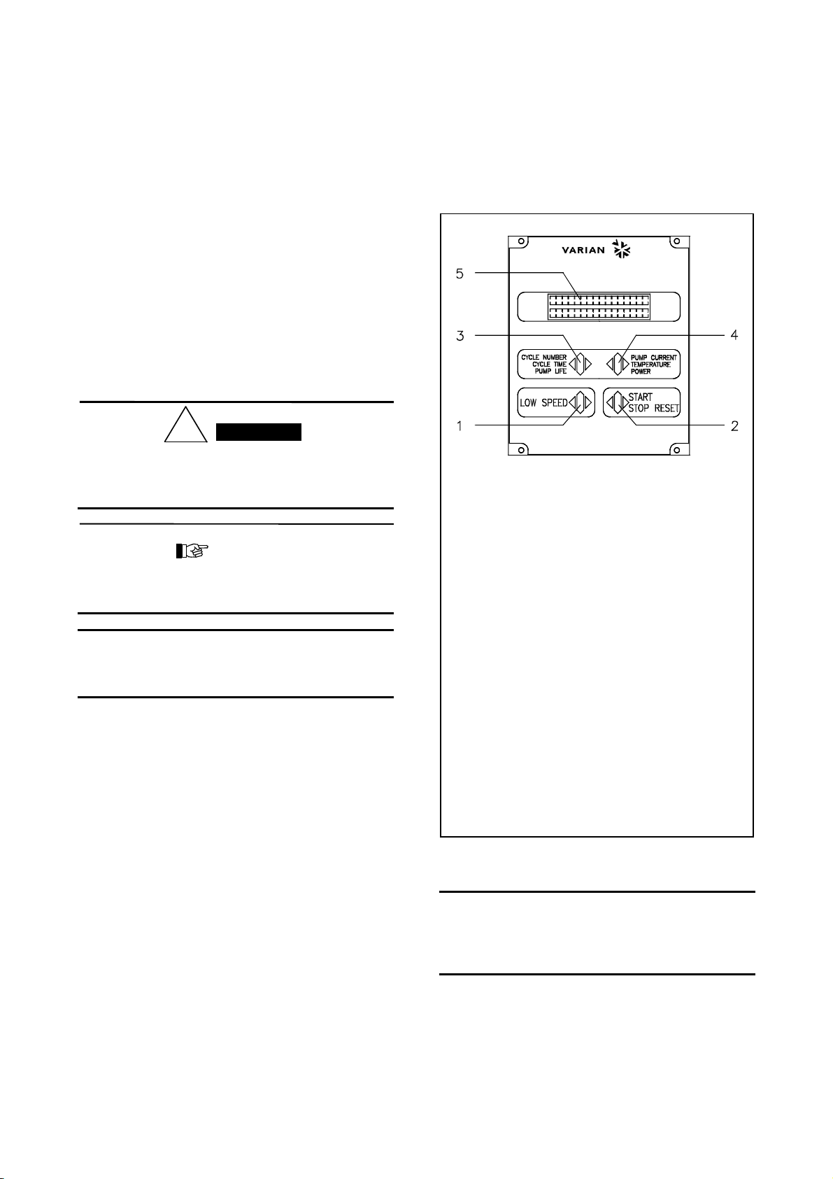
Commandes, indicateurs et connecteurs du
hand held terminal
On présente ci-dessous le tableau de commande du
hand held terminal. Pour de plus amples détails, se
reporter à la section "Technical Information".
1. Interrupteur de sélection du mode LOW SPEED. Il n'est
actif que lorsque le mode de commande est sélectionné
depuis le tableau frontal. En le pressant une fois, la
pompe tourne à 2/3 environ de la vitesse nominale. En
le pressant une deuxième fois, on désactive le mode
LOW SPEED.
2. Interrupteur envoyant les commandes de START,
STOP ou RESET. Il n'est actif que lorsque le mode de
commande est sélectionné depuis le tableau frontal.
Une première pression de l'interrupteur active la phase
de mise en marche; une deuxième pression provoque
l'arrêt de la pompe. Si la pompe s'est arrêtée
automatiquement à cause d'une panne, il faut presser
cet interrupteur une première fois pour effectuer la mise
à zéro du dispositif et une deuxième fois pour remettre
la pompe en marche.
3. Interrupteur rappelant sur l'afficheur les paramètres de
cycle number, cycle time et pump life.
4. Interrupteur rappelant sur l'afficheur les paramètres de
pump current, pump temperature, pump power et
rotational speed. Il est toujours actif, indépendamment
du mode de fonctionnement choisi. En pressant
simultanément les interrupteurs 3 et 4 pendant 2
secondes au moins, on active un programme avec
lequel il est possible de programmer certains
paramètres opérat-ionnels.
5. Ecran alphanumérique à cristaux liquides: matrice de
points, 2 lignes x 16 caractères.
Tableau avant du Hand Held Terminal
NOTE
Les fonctions de LOW SPEED et START/STOP
RESET ne sont actives que lorsque le mode de
commande est séléctionné depuis le tableau frontal (se
reporter à la section "Technical Information").
DANGER!

INSTRUCTIONS FOR USE
4
87-900-847-01 (B)
GENERAL INFORMATION
This equipment is destined for use by professionals.
The user should read this instruction manual and any
other additional information supplied by Varian before
operating the equipment. Varian will not be held
responsible for any events occurring due to non-
compliance, even partial, with these instructions,
improper use by untrained persons, non-authorised
interference with the equipment or any action contrary
to that provided for by specific national standards.
The following paragraphs contain all the information
necessary to guarantee the safety of the operator when
using the equipment. Detailed information is supplied in
the "Technical Information".
This manual uses the following standard protocol:
!
The warning messages are for attracting the attention
of the operator to a particular procedure or practice
which, if not followed correctly, could lead to serious
injury.
CAUTION!
The caution messages are displayed before
procedures which, if not followed, could cause damage
to the equipment.
NOTE
The notes contain important information taken from the
text.
STORAGE
When transporting and storing the devices, the
following environmental requirements should be
satisfied:
•temperature: from -20 °C to + 70 °C
•relative humidity: 0 - 95%
(without condensation)
PREPARATION FOR INSTALLATION
The device is supplied in a special protective packing.
If this shows signs of damage which may have
occurred during transport, contact your local sales
office. When unpacking the Hand-held terminal, ensure
that it is not dropped or subjected to any form of
impact. Do not dispose of the packing materials in an
unauthorized manner. The material is 100% recyclable
and complies with EEC Directive 85/399.
Hand-held Terminal Controls, Indicators and
Connectors
The following paragraph illustrates the Hand-held
terminal panel. More details are contained in the
appendix "Technical Information".
1. Keyboard push-button for LOW SPEED mode
selection. It is active only when the front panel
operation has been selected. Pressed once, the pump
runs at about 2/3 of the nominal speed. To unselect the
mode, press the push-button again.
2. Keyboard push-button for START, STOP, RESET
mode selection. It is active only when the front panel
operation has been selected. By pressing once the
starting phase begins; if pressed again it stops the
pump. If the pump has been stopped automatically by
a fault, this push-button must be pressed once to reset
the device and a second time to restart the pump.
3. Keyboard push-button to recall on the display the cycle
number, cycle time and pump life.
4. Keyboard push-button to recall on the display the pump
current, pump temperature, pump power and rotational
speed. It is always active regardless of the operating
mode selected. Push-buttons 3 and 4, if pressed
together for at least 2 seconds, put the device in a
routine where it is possible to program some operation
parameters.
5. LCD back-lighted alphanumeric display: dot matrix 2
lines x 16 characters.
Hand Held Terminal Front Panel
NOTE
LOW SPEED and START/STOP RESET functions are
active only if the FRONT panel mode of operation is
selected (see "Technical Information").
WARNING!

TECHNICAL INFORMATION
5
87-900-847-01 (B)
HAND-HELD TERMINAL DESCRIPTION
The Hand-held terminal is on LCD alphanumeric
display and keyboard, which provides useful real time
indications of the operating conditions/parameters of
the Turbo-V 60 pump series when connected to a
Turbo-V 60 controller without front panel.
Moreover, it is possible to reprogram the controller
parameters or troubleshooting pump/controller.
The Hand-held terminal, 188 mm height x 110 mm wide
x 41 mm deep (7.4" x 4.3" x 1.6"), is connected and
powered to the Turbo-V controller via a 1.5 meters (5 ft)
cable.
USE
General
Make all vacuum manifold and electrical connections and
refer to Turbo-V pump instruction manual before to
operating the Turbo-V controller.
!
To avoid injury to personnel and damage to the
equipment, if the pump is laying on a table make sure it
is steady. Never operate the Turbo-V pump if the pump
inlet is not connected to the system or blanked off.
Connect the hand-held terminal to the Turbo-V controller.
Plug the controller power cable into a suitable power
source.
If the hand-held terminal is used to monitor the pump
operating conditions, follow paragraph "Monitor Mode";
if reprogramming or trouble shooting is required, follow
paragraph "Program Mode"; and the following
paragraph.
Monitor Mode
By pressing the CURRENT push-button, the display
shows:
I=0.00A P= 0W
X..KRPMXX°C
where:
•I= is the DC current drawn by the pump range
(0.00 to 9.99 Ampere)
•P= is the DC power drawn by the pump (range 0 to
999 Watt)
•KRPM = is the theoretical rotational speed of the
pump as a function of the controller output
frequency (range 17 to 99 KRPM)
•°C = is the temperature of the outer ring of the
upper bearing (range 00 to 99 °C)
•X = during operation a selected set point condition
(1 or 2 contrast inverted) appears when the
programmed threshold speed value is not reached.
•Press the CYCLE NUMBER once and the display
shows:
XXXXCYCLE XXXXXm
PUMP LI FE XXXXXh
where:
•CYCLE = are the cycles performed (range 0 to 9999)
•m= is the elapsed time related to the cycle number
displayed (range 0 to 99999 minutes)
•PUMP LIFE = is the total operation time of the pump
(range 0 to 99999 hours).
Program Mode
Refer to paragraph "Speed Adjustment" to program/
adjust the high and low speed values. This feature is
only applicable when a dedicated software is installed
on the Turbo-V 60 controller microprocessor (e.g. for
leak detector operation).
FRONT / REMOTE/ 232 Selection
•Press CYCLE NUMBER and PUMP CURRENT
push-buttons together for at least 2 seconds and
the processor enters in a routine where it is
possible to program the controller.
In this routine, the CYCLE push-button is used for
choosing/changing the value or condition; the
PUMP CURRENT push-button is used to enter and
confirm the value. At any time it is possible to exit
this routine by pressing the CYCLE and PUMP
CURRENT push-buttons at the same time for at
least 2 seconds.
The display shows:
FRONT/REMOTE/ 232
SELECT I ON : XXXXXX
where: XXXXXX = means the word FRONT or
REMOTE, or RS 232 depending on the last
selection.
Select the FRONT panel operation if the front panel
command is used.
After choosing the desired selection by pressing the
CYCLE push-button, press the PUMP CURRENT
push-button to enter the value.
WARNING!

TECHNICAL INFORMATION
6
87-900-847-01 (B)
The display shows:
RS232
BAUD RATE XXXX
where: XXXX = means 600, 1200, 2400, 4800, 9600
baud rate for the host computer or printer
communication.
If necessary, select the desired value by pressing the
CYCLE NUMBER, then enter the value by pressing the
PUMP CURRENT push-button.
The display shows:
RS2 3 2 HOST / PR I NT
SELECT I ON : XXXXX
where: XXXX = means HOST or PRINT.
Select HOST or PRINT by pressing the CYCLE
push-button.
With the RS 232 connected, a bidirectional communication
is established by selecting HOST. Data are sent to an
external computer every time the external computer asks
for the values.
The data available are:
•Pump/controller operating condition
•Cycle time
•Pump life
•Pump temperature
•Pump current
•Pump voltage
•Controller output frequency
•Cycle number
•R1 condition
•R2 contition
If PRINT is selected and a printer is connected on
RS 232 line, a unidirectional communication is
established and every minute the data are sent to the
printer, even if the pump is not running.
The set of data available are:
•Pump speed KRPM
•Pump temperature
•Pump current A
•Pump power W
•R1 condition
•R2 contition
Confirm the selection by pressing the PUMP
CURRENT pushbutton.
The display will be as shown in the following figure.
Monitor Relay Programming
•The display shows:
SPEED THRESHOLD
SELECT I ON : XXKRPM
where: XXKRPM = is the switch point of relay R1 at
the preset turbopump speed, adjustable from 00 to
99 KRPM.
The speed threshold will condition the R1 and R2
operation (see the following cycle diagram).
Select the first number by pressing the CYCLE
NUMBER push-button, then enter the value by
pressing the PUMP CURRENT push-button.
Do the same for the second number.
After pressing the PUMP CURRENT the second
time, the display will be as shown in the following
figure.
RUN - UP T I ME
SEL : XXh XXm XXs
where: RUN-UP TIME = is the interval time from
start to speed threshold value in hours, minutes,
seconds. Select from 00 to 99 hours, and from 00 to
59 minutes or seconds.
Select the run-up time according to the chamber
volume and/or operating cycle feature by pressing
the CYCLE NUMBER push-button to select the
desired number, then press the PUMP CURRENT
to enter the data.
When the last digit is entered, the display will be as
shown in the following figure.
DELAY EVEN AFTER
THRESHOLD : XXX
where:
XXX = YES or NO.
By pressing the CYCLE NUMBER pushbutton, select
YES if relay R2 must operate only after the run-up
time or select NO when the R2 operation is needed
right from start of the turbopump and after the
rotational speed of the turbopump exceeds for the
first time the speed threshold value as shown in the
following figure.

TECHNICAL INFORMATION
7
87-900-847-01 (B)
After selection, press PUMP CURRENT to confirm; the
display will be as show in the following figure.
Cycle diagram
Reset Command
•The display shows:
PUMP L I FE XXXXXh
RESET? XXX
where:
•PUMP LIFE = is the elapsed operating time range 000
to 99999 hours.
•RESET XXX = YES or NO.
If YES is selected, the pump life shall be reset to 000. After
selecting YES, press the PUMP CURRENT
push-button to enter the command and the display shows
as follows:
I=0.00A P= 0W
X..KRPMXX°C
NOTE
When PUMP LIFE is reset to 000, the CYCLE number
is also reset to 000.

TECHNICAL INFORMATION
8
87-900-847-01 (B)
Starting the Pump
If the forepump and vent device are not operated by the
controller, close the vent valve and switch on the
forepump.
NOTE
With the FRONT panel operation selected, the
REMOTE and RS232 operations are inoperative;
conversely, the CYCLE NUMBER and PUMP
CURRENT pushbuttons are always active, even when
the operating mode selected is REMOTE or RS 232.
•Press the START push-button or use the remote or
RS 232 start signal, the display shows:
PUMP I S START I NG
12 XX KRPM
where:
12= contrast inverted identifies the set point
condition:
−1 is displayed when relay R1 is de-energized.
−2 is displayed when relay R2 is energized.
XX KRPM = indicates the actual theoretical
rotational speed of the pump as a function of the
controller output frequency (range 3 to 99 KRPM).
•After START command, frequency output will be at
the maximum level, then the frequency will
decrease to a value proportional to the pump
rotational speed (1/4 of nominal frequency if the
pump is completely stopped).
The pump will accelerate to its normal rotational
speed and when this speed is reached, the display
will be as follows, even if any previous display
selection was made, and the normal condition has
been reached.
NORMA L OPERAT I ON
XX KRPM
where: XX = indicates the rotational speed.
During acceleration of the pump or during any
operating condition, it is always possible to select
the other parameters to be displayed (PUMP
CURRENT or CYCLE NUMBER push-buttons).
If this is the case when the pump reaches the
normal speed, the display reverts to the previous
figure.
Operating the Pump
After the starting period, if the system has a vacuum
leak or the pressure in the pump/chamber is high (from
1 mbar to atmosphere), the pump continues to operate
indefinitely. If the gas load at the turbopump inlet flange
continues to stay high, the power drawn by the
turbopump increases up to the maximum value. Than
the Turbo-V pump is slowed down in proportion to the
gas load at least until it reaches 3 KRPM.
Even if any previous display selection was made.
This will occur either in NORMAL operation or with the
LOW SPEED selected. As soon as the gas load
decreases, the pump will automatically accelerate to
reach normal operation. The pump can be stopped at
any rotational speed and can be restarted at any
rotational speed from either the front panel buttons or
the remote connections. The controller automatically
synchronizes the output to the rotational speed of the
pump and then accelerates linearly up to the nominal
speed or within steps if the Soft Start has been
selected.
Low Speed Operation
NOTE
With the FRONT panel operation selected, the remote
and RS 232 operations are inoperative; conversely, the
CYCLE NUMBER and PUMP CURRENT pushbuttons
are always active, even when the operating mode
selected is REMOTE or RS 232.
This feature is provided for operating the pump at
moderate high pressure with high gas throughput. To
operate in this low speed mode, engage the LOW
SPEED push-button, either before starting the pump or
after it is operating.
If LOW SPEED is selected before starting the pump,
the display shows as follows:
PUMP READY : PUSH
START BUTTON LS
where: LS = means low speed mode is selected.

TECHNICAL INFORMATION
9
87-900-847-01 (B)
After starting, a LS appears on the right bottom corner
of the following displays.
With normal LOW SPEED operation, the pump will run
at about 2/3 of its nominal speed and achieves a base
pressure somewhat higher than the standard
specifications. If the gas load becomes higher, the
controller output frequency and voltage start to
decrease automatically, and the Turbo-V pump is
slowed down in proportion to the gas load until it
reaches about 25% of the nominal speed.
If the LOW SPEED mode is selected after normal
operating condition is reached, the display shows:
APPROACH I NG LS
XX KRPM LS
while approaching the low speed value.
When the low speed mode is deselected, the display
shows:
NORMA L OPERAT I ON
XX KRPM
The pump starts to accelerate to its rotational speed.
Speed Adjustment
For some dedicated applications (e.g. leak detection)
where high and low speed need to be changed and
adjusted, a dedicated software is installed on the
Turbo-V controller microprocessor.
By pressing CYCLE NUMBER and PUMP CURRENT
pushbuttons together for at least 4 seconds, the
processor enters in a routine where it is possible to
adjust the rotational speed.
The display shows:
H I GH SPEED
SELECT : XXXXXRPM
where:
•XXXXX = is the pump rotational HIGH SPEED value
selected.
In this routing the CYCLE pushbutton is used to
increase the speed value and the LOW SPEED
pushbutton is used to decrease the value. When the
right value is chosen use the PUMP CURRENT
pushbutton to enter and confirm the value.
The display shows:
LOW SPEED
SELECT : XXXXXRPM
where:
•XXXXX = is the pump rotational LOW SPEED
value selected.
After choosing the desired value by pressing the
CYCLE pushbutton for increasing, and LOW SPEED
pushbutton for decreasing, press the PUMP CURRENT
pushbutton to enter the value.
NOTE
If different values of high or low speed are selected, the
pump rotational speed will change (increase or
decrease) only when the routing program ends.
The display shows:
FRONT/REMOTE/ 232
SELECT I ON : XXXXXX
Continue until the end of the paragraph "Front/Remote/
232 Selection" the proceed to paragraph "Reset
Command".
Monitor relay programming not applicable when the
speed adjustment software is installed.

TECHNICAL INFORMATION
10
87-900-847-01 (B)
Pump Shutdown
Press the front panel STOP pushbutton or remove the
remote signal; the power from the turbopump will be
removed and the pump will begin to slow down.
An emergency stop signal is provided via a remote
contact. This signal is active in any of the three
operation selections: FRONT, REMOTE, RS 232; when
activated, the display will be as shown in the following
figure.
SYSTEM
OVERR I DE
Power Failure
In the event of a power failure (momentary or long
term), the Turbo-V controller will stop the turbopump
and all the interconnected pumps/devices. The Turbo-V
vent valve device, if used, will vent the turbopump only
if the power failure is longer than the preset delay time.
When power is restored, the Turbo-V controller
automatically restarts the interconnected devices and
the turbopump in the proper sequence.
The display shows:
PUMP I S START I NG
12 XX KRPM
until normal operation achieved.
Remote Control Mode Operation
If remote signals are used to operate the controller, it
must be programmed for remote operation (see
paragraph "Program Mode") and when ready to start,
the display shows as in the following figure.
PUMP READY : USE
REMOTE START
START/STOP and LOW SPEED pushbuttons are
inoperative, while the CYCLE NUMBER and PUMP
CURRENT pushbuttons are always active.
RS 232 Control Mode Operation
If the RS 232 option is installed and the controller has
been programmed for RS 232 operation, the controller
may be driven by a computer and when ready to
operate the display shows as in the following figure.
PUMP READY : USE
RS2 3 2 L I NE
The START/STOP and LOW SPEED functions are
under computer control, while the CYCLE NUMBER
and PUMP CURRENT front panel pushbuttons are
always active.

TECHNICAL INFORMATION
11
87-900-847-01 (B)
ERROR MESSAGES
For a certain type of failure, the controller will
self-diagnose the error and the following messages will
be displayed.
NOTE
If the pump is not connected, the display will be as
shown in the following figure.
CHECK CONNECT I ON
TO PUMP
Check connection between controller and pump, then
press START RESET pushbutton twice to start the
pump.
NOTE
If the P1 input connector is not in position with the link
or the external interlock connections are open, when
the START pushbutton is pressed the display will be as
shown in the following figure.
PUMP WA I T I NG
INTERLOCK
Disconnect the input connector and check the link or
the external interlock, then install the connector to start
the pump.
NOTE
If the upper bearing/pump temperature exceed 60 ºC,
the pump is shut off, and the display will be as shown
in the following fiugre.
FAULT : PUMP
OVERTEMP .
The message will stay on until the temperature
decreases below threshold value. Press the
STOP RESET pushbutton twice to start the pump.
NOTE
If the controller transformer temperature exceeds 90°C,
the pump is shut off, and the display will be as shown
in the following figure.
FAULT : CONTROLLER
OVERTEMPERATURE
The message will stay on until the temperature
decreases below threshold value. Press the STOP
RESET pushbutton twice to start the pump.
NOTE
If in normal condition the current drawn by the pump is
higher than programmed (1.5 A), the pump and the
interconnected devices are switched off and the display
will be as shown in the following figure.
FAULT :
TOO H I GH LOAD
Check that pump rotor is free to rotate then press the
STOP RESET pushbutton twice to start the pump.
NOTE
If the output connection is shorted or the pump rotor is
locked, the display will be as shown in the following
figure.
FAULT :
SHORT C I RCU I T
Check connections and shortages between pump and
controller, then press the STOP RESET pushbutton
twice to start the pump.
NOTE
If the pump is stopped by an emergency stop signal
provided via a remote contact, the display will be as
shown in the following figure.
SYSTEM
OVERR I DE
Remove the controller power cable and check the
emergency condition. Then reconnect the power cable
and press the START pushbutton to start the pump.

Request for Return
1. A Return Authorization Number (RA#) WILL NOT be issued until this Request for Return is completely filled out,
signed and returned to Varian Customer Service.
2. Return shipments shall be made in compliance with local and international Shipping Regulations (IATA, DOT, UN).
3. The customer is expected to take the following actions to ensure the Safety of workers at Varian:(a) Drain any oils or
other liquids, (b) Purge or flush all gasses, (c) Wipe off any excess residues in or on the equipment, (d) Package the
equipment to prevent shipping damage, (for Advance Exchanges please use packing material from replacement unit).
4. Make sure the shipping documents clearly show the RA# and then return the package to the Varian location nearest you.
North and South America
Varian Vacuum Technologies
121 Hartwell Ave
Lexington, MA 02421
Phone : +1 781 8617200
Fax: +1 781 8609252
Europe and Middle East
Varian SpA
Via Flli Varian 54
10040 Leini (TO) – ITALY
Phone: +39 011 9979111
Fax: +39 011 9979330
Asia and ROW
Varian Vacuum Technologies
Local Office
CUSTOMER INFORMATION
Company name: ..………………….……..……………….………………………………..……………………...…………..….
Contact person: Name: ……………………………………..… Tel: ……………………….…...…………….….…....
Fax: …………………………….…...…..…… E-Mail: ..……………………..…………..…..…..…..
Ship Method: …………….……....…… Shipping Collect #: ………….…..………… P.O.#: ………………….…......………..
Europe only: VAT reg. Number: ………………..……………... USA only:Taxable Non-taxable
Customer Ship To: ………………………….……… Customer Bill To: …………………..……………...
……………..…………………... ..………………………………...
………………..………………... ..………………………………...
PRODUCT IDENTIFICATION
Product Description Varian P/N Varian S/N Purchase Reference
TYPE OF RETURN (check appropriate box)
Paid Exchange Paid Repair Warranty Exchange Warranty Repair Loaner Return
Credit Shipping Error Evaluation Return Calibration Other ……………….
HEALTH and SAFETY CERTIFICATION
Varian Vacuum Technologies CAN NOT ACCEPT any equipment which contains BIOLOGICAL HAZARDS or
RADIOACTIVITY. Call Varian Customer Service to discuss alternatives if this requirement presents a problem.
The equipment listed above (check one):
HAS NOT been exposed to any toxic or hazardous materials
OR
HAS been exposed to any toxic or hazardous materials. In case of this selection, check boxes for any materials that
equipment was exposed to, check all categories that apply:
Toxic Corrosive Reactive Flammable Explosive Biological Radioactive
List all toxic or hazardous materials. Include product name, chemical name and chemical symbol or formula.
.……………………………………………………………………………………………………………………..
Print Name: …………………………………. Customer Authorized Signature: ……………...…………………….
Print Title: …………………………………... Date: ..…../..…../……
NOTE: If a product is received at Varian which is contaminated with a toxic or hazardous material that was not disclosed, the customer
will be held responsible for all costs incurred to ensure the safe handling of the product, and is liable for any harm or injury to Varian
employees as well as to any third party occurring as a result of exposure to toxic or hazardous materials present in the product.
Do not write below this line
Notification (RA)#: ……………………….……….. Customer ID#: ……….…………. Equipment #: ……………………..

Request for Return
FAILURE REPORT
TURBO PUMPS and TURBOCONTROLLERS
POSITION PARAMETERS
Does not start Noise Vertical Power: Rotational Speed:
Does not spin freely Vibrations Horizontal Current: Inlet Pressure:
Does not reach full speed Leak Upside-down Temp 1: Foreline Pressure:
Mechanical Contact Overtemperature Other: Temp 2: Purge flow:
Cooling defective …………………. OPERATION TIME:
TURBOCONTROLLER ERROR MESSAGE:
ION PUMPS/CONTROLLERS VALVES/COMPONENTS
Bad feedthrough Poor vacuum Main seal leak Bellows leak
Vacuum leak High voltage problem Solenoid failure Damaged flange
Error code on display Other Damaged sealing area Other
Customer application: Customer application:
LEAK DETECTORS INSTRUMENTS
Cannot calibrate No zero/high backround Gauge tube not working Display problem
Vacuum system unstable Cannot reach test mode Communication failure Degas not working
Failed to start Other Error code on display Other
Customer application: Customer application:
PRIMARY PUMPS DIFFUSION PUMPS
Pump doesn’t start Noisy pump (describe) Heater failure Electrical problem
Doesn’t reach vacuum Over temperature Doesn’t reach vacuum Cooling coil damage
Pump seized Other Vacuum leak Other
Customer application: Customer application:
FAILURE DESCRIPTION
(Please describe in detail the nature of the malfunction to assist us in performing failure analysis):
NOTA: Su richiesta questo documento è disponibile anche in Tedesco, Italiano e Francese.
REMARQUE : Sur demande ce document est également disponible en allemand, italien et français.
HINWEIS: Auf Aufrage ist diese Unterlage auch auf Deutsch, Italienisch und Französisch erhältlich.

Sales and Service Offices
Argentina
Varian Argentina Ltd.
SucursalArgentina
Av. Ricardo Balbin 2316
1428 Buenos Aires
Argentina
Tel: (54) 1 783 5306
Fax: (54) 1 786 5172
Australia
Varian Australia Pty Ltd.
679-701 Springvale Road
Mulgrave, Victoria ZZ 3170
Australia
Tel: (61) 395607133
Fax: (61) 395607950
Benelux
Varian Vacuum Technologies
Rijksstraatweg 269 H,
3956 CP Leersum
The Netherlands
Tel: (31) 343 469910
Fax: (31) 343 469961
Brazil
Varian Industria e Comercio Ltda.
Avenida Dr. Cardoso de Mello 1644
Vila Olimpia
Sao Paulo 04548 005
Brazil
Tel: (55) 11 3845 0444
Fax: (55) 11 3845 9350
Canada
Central coordination through:
Varian Vacuum Technologies
121 Hartwell Avenue
Lexington, MA 02421
USA
Tel: (781) 861 7200
Fax: (781) 860 5437
Toll Free: (800) 882 7426
China
Varian Technologies - Beijing
Room 1201, Jinyu Mansion
No. 129A, Xuanwumen Xidajie
Xicheng District
Beijing 1000031 P.R. China
Tel: (86) 10 6608 1530
Fax: (86) 10 6608 1534
France and Wallonie
Varian s.a.
7 avenue des Tropiques
Z.A. de Courtaboeuf – B.P. 12
Les Ulis cedex (Orsay) 91941
France
Tel: (33) 1 69 86 38 13
Fax: (33) 1 69 28 23 08
Germany and Austria
Varian Deutschland GmbH
Alsfelder Strasse 6
Postfach 11 14 35
64289 Darmstadt
Germany
Tel: (49) 6151 703 353
Fax: (49) 6151 703 302
India
Varian India PVT LTD
101-108, 1st Floor
1010 Competent House
7, Nangal Raya Business Centre
New Delhi 110 046
India
Tel: (91) 11 5548444
Fax: (91) 11 5548445
Italy
Varian Vacuum Technologies
Via F.lli Varian, 54
10040 Leini, (Torino)
Italy
Tel: (39) 011 997 9111
Fax: (39) 011 997 9350
Japan
Varian Vacuum Technologies
Sumitomo Shibaura Building, 8th Floor
4-16-36 Shibaura
Minato-ku, Tokyo 108
Japan
Tel: (81) 3 5232 1253
Fax: (81) 3 5232 1263
Korea
Varian Technologies Korea, Ltd.
Shinsa 2nd Bldg. 2F
966-5 Daechi-dong
Kangnam-gu, Seoul
Korea 135-280
Tel: (82) 2 3452 2452
Fax: (82) 2 3452 2451
Mexico
Varian S.A.
Concepcion Beistegui No 109
Col Del Valle
C.P. 03100
Mexico, D.F.
Tel: (52) 5 523 9465
Fax: (52) 5 523 9472
Ta i w a n
Varian Technologies Asia Ltd.
18F-13 No.79, Hsin Tai Wu Road
Sec. 1, Hsi Chih
Taipei Hsien
Taiwan, R.O.C.
Tel: (886) 2 2698 9555
Fax: (886) 2 2698 9678
UK and Ireland
Varian Ltd.
28 Manor Road
Walton-On-Thames
Surrey KT 12 2QF
England
Tel: (44) 1932 89 8000
Fax: (44) 1932 22 8769
United States
Varian Vacuum Technologies
121 Hartwell Avenue
Lexington, MA 02421
USA
Tel: (781) 861 7200
Fax: (781) 860 5437
Toll Free: (800) 882 7426
Other Countries
Varian Vacuum Technologies
Via F.lli Varian, 54
10040 Leini, (Torino)
Italy
Tel: (39) 011 997 9111
Fax: (39) 011 997 9350
Internet Users:
Customer Service & Technical Support:
vtt.customer.service@varianinc.com
Worldwide Web Site:
www.varianinc.com/vacuum
Order On-line:
www.evarian.com
Representatives in most countries
11/01
Table of contents
Other Varian Touch Terminal manuals