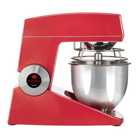
Varimixer V80 User manual

V
V80
V80PL
V100PL
EN
Operating Instructions
DRN: 20080-1536
2022 10 31
Varimixer USA
2215 East River Road
Moraine, Ohio 45439
P: (800) 222-1138
varimixerusa.com
V80 : 80002012
V100 :100002125
Valid from machine number:

2
Limited Mixer Warranty - 10 qt to 150 qt
VARIMIXER warrants to the original purchaser of new equipment that said equipment, when installed in accordance
with our instructions within North America and subjected to normal use, is free from defects in material or workmanship
for a period of 4 years. Wear parts, such as belts, are excluded. Hub attachments, such as shredders, slicers and
grinders have a 1 year warranty that only covers parts. Warranty begins on date of factory shipment to an end user, or
up to 6 months after factory shipment to a dealer or distributor. Payment by VARIMIXER for service under this warranty
requires that service be authorized in advance. Contact VARIMIXER Technical Support to arrange for service.
THIS WARRANTY IS IN LIEU OF ALL OTHER WARRANTIES, WHETHER EXPRESSED OR IMPLIED. VARIMIXER
EXPRESSLY DISCLAIMS ANY IMPLIED WARRANTY OF MERCHANTABILITY OR EXPRESSED OR IMPLIED
WARRANTY OF FITNESS FOR A PARTICULAR PURPOSE.
VARIMIXER’S OBLIGATION AND LIABILITY UNDER THIS WARRANTY IS EXPRESSLY LIMITED TO REPAIRING
AND REPLACING EQUIPMENT WHICH PROVES TO BE DEFECTIVE IN MATERIAL OR WORKMANSHIP WITHIN
THE APPLICABLE WARRANTY PERIOD. All repairs pursuant to this Warranty will be performed by an Authorized
Designated VARIMIXER Service Location during normal working hours. IN NO EVENT SHALL VARIMIXER BE
LIABLE FOR INCIDENTAL OR CONSEQUENTIAL DAMAGES TO BUYER OR ANY THIRD PARTY, INCLUDING,
WITHOUT LIMITATION, LOSS OF PROPERTY, PERSONAL INJURY, LOSS OF BUSINESS OR PROFITS OR OTHER
ECONOMIC LOSSES, OR STATUTORY OR EXEMPLARY DAMAGES, WHETHER IN NEGLIGENCE, WARRANTY,
STRICT LIABILITY, OR OTHERWISE.
This warranty is given only to the rst purchaser from a retail dealer. No warranty is given to subsequent transferees.
This warranty does not cover product failures caused by: failure to maintain, neglect, abuse, damage due to excess
water, re, normal wear, improper set up and use. Periodic maintenance is not covered.
Example of items not covered under warranty, but not limited to just these items:
1. Acts of God, re, water damage, vandalism, accident, theft.
2. Freight damage.
3. Improper installation or alteration of equipment.
4. Use of generic or after market parts.
5. Repairs made by anyone other than a VARIMIXER designated servicer.
6. Lubrication.
7. Expendable wear parts. (This includes the bowl, at beater, wire whip, spiral dough hook,
and the pastry knife.)
8. Cleaning of equipment.
9. Misuse or abuse.
This warranty is not in force until such time as a properly completed, digitally signed Installation/Warranty Registration
has been received by VARIMIXER within 30 days from the date of installation.
Register online at www.varimixerusa.com/support/warranty-registration-form.
THE FOREGOING WARRANTY PROVISIONS ARE A COMPLETE AND EXCLUSIVE STATEMENT BETWEEN THE
BUYER AND SELLER. VARIMIXER NEITHER ASSUMES NOR AUTHORIZES ANY PERSONS TO ASSUME FOR IT
ANY OTHER OBLIGATION OR LIABILITY IN CONNECTION WITH SAID EQUIPMENT.
WARRANTY REGISTRATION
GO TO VARIMIXERUSA.COM
TO FILL OUT AND SUBMIT YOUR WARRANTY REGISTRATION.
VARIMIXERUSA.COM/SUPPORT/WARRANTY-REGISTRATION-FORM

3
Caution -READ BEFORE OPERATING- Caution
Always observe local laws and regulations, paying particular attention to the operator’s age, physi-
cal and mental condition.
This manual should be seen as an integral part of the mixer and should be kept by the machine
throughout its working life.
Before the machine is commissioned, it is important to read these instructions thoroughly.
The manufacturer may update the product manual without updating this copy of the manual.
- Varimixer recommends all operators must be at least 18 years of age.
- All operators must be thoroughly trained before being allowed to operate the mixer.
- NEVER reach into the bowl when the mixer is running.
- Do not wear loose clothing or rings while operating the mixer.
- Stop the mixer and lower the bowl before adding ingredients, scraping the bowl, removing the
agitator, or removing the product.
- Stop the mixer before removing or installing attachments into the drive hub.
- Do not attempt to assemble or disassemble attachments while mounted into the drive hub.
- Always use the pusher plate with the slicer/meat grinder attachments.
- NEVER bypass the safety mechanisms supplied on the mixer. Doing so can cause injury and
is the responsibility of the user to ensure these safety mechanisms are operating properly.

4
The machine should be unpacked and the packaging disposed of according to regulations ap-
plicable in the country concerned.
Before the machine is removed from the pallet, check that all parts are present with the machine:
• Safety guard, Ingredient chute, Bowl.
• Grease gun, Rubber feet and Spacers for height adjustment.
• Bowl trolley, whip, beater, hook, scraper with blade and attachment drive, if these were selected
with the order.
The machine is mounted onto the pallet with four bolts, to release the machine from the pallet,
unscrew the 4 nuts with the supplied tool and hammer out the bolts.
General............................................................................................................................................2
Unpacking........................................................................................................................................2
Safety ..............................................................................................................................................3
Installation of the Mixer....................................................................................................................3
Cleaning ..........................................................................................................................................4
Ingredient chute...............................................................................................................................4
The maximum capacity of the Mixer................................................................................................5
Recommended maximum speeds...................................................................................................5
Operating the mixer.........................................................................................................................6
Operating the frontpanel..................................................................................................................7
Construction of the Mixer.................................................................................................................8
Maintenance and lubrication............................................................................................................8
Adjustment of special V-belt ............................................................................................................9
Adjustment of speed........................................................................................................................9
Adjustments of speed (low and high speed cam disks).................................................................10
Adjustment of bowl xing...............................................................................................................12
Adjustment of bowl centering ........................................................................................................12
Adjustment of bowl height .............................................................................................................13
List of errors and possible solutions ..............................................................................................14
Error codes....................................................................................................................................14
Manual reset of motor protection relay..........................................................................................15
Principle electrical diagram............................................................................................................16
Cleaning guide...............................................................................................................................20
Contents of the Declaration of conformity for machinery...............................................................22

5
Install the machine so there is workspace for normal use
and maintenance.
The oor of the workspace where the machine is installed
must be rm, even and level.
The mixer must be mounted with the supplied feet, that elimi-
nate both shaking and rusting. If the oor is not completely
even, the supplied spacers are inserted under the mixer’s
feet to ensure the machine is level.
Foundation bolts in the oor are only necessary under spe-
cial conditions, e.g. on ships
.
The ambient temperature around the machine must not ex-
ceed 45
º
C
Connection to power:
The mixer is to be connected to power via a
plug. The plug must be dimensioned for min. 16
A, 208/480V~, IP44
When connecting;
3 phases + earth, use a 4 pole plug.
Before the mixer is connected to power, it should be checked
that the voltage and frequency printed on the machine label
is correct in relation to the place of installation. The machine
label is located on the top right side of the mixer.
Machine, bowl, tools safety guard and ingredient chute must
be cleaned thoroughly before use – see section Cleaning,
page 4.
The mixer is designed for commercial use in kitchens, ca-
tering outlets and bakeries.
The mixer must not be used in an explosive atmosphere.
The mixer may only be used as specied in this manual.
The mixer is designed for manufacture of pro-
ducts which do not during processing cause
reactions or emit substances which may be det-
rimental to the user.
Putting your ngers in the bowl while the mixer
is running may cause injuries.
Electrical connection must only be carried out
by a certied electrician.
Lifting equipment should always be used to
move the mixer.
When the mixer is moved, it should be in an up-
right position at all times.
The mixer must not be pulled or lifted by the
bowl lift handle (V80 only) and speed selection
handle.
Powdery ingredients:
Do not pour powdery ingredients into the bowl
from a great height.
Bags of e.g. our should be opened at the
bottom, down into the bowl.
Do not increase to maximum speed too quickly.
Mixer and safety guard are equipped with strong magnets.
Area with magnets
Safety guard.
Area with magnets
Bowl detection.
Area with magnets
Safety guard.

6
V80 340 kg
V100 395 kg
When ingredients are to be added while the
machine is working, use the supplied ingredi-
ent chute made of stainless steel.
Remove tool if mounted, lift up the bowl arms
with the bowl to normal working position and
start the mixer. Check the direction of rotation
of the planetary head: the planetary head must
rotate in the direction as stated by the arrow
above the planetary head. If the direction of ro-
tation is wrong, 2 of the phase wires of the con-
necting cable must be inverted.
Before any cleaning, disconnect the power
supply to the machine by disconnecting the
connection cable from the connection point
The machine should never be rinsed with a
hose.
To assist in the preparation of customer-specic
cleaning plans, Varimixer A/S has, based on current
legislation, prepared detailed cleaning instructions,
included at the end of this manual and the latest
version can be found at varimixer.com

7
Capacities per mix Tool V80 V100
Egg whites Whip qt 4 5
Whipped cream Whip qt 17 26
Buttercream frosting Whip *) lb 71 99
Mashed potatoes Beater *) lb 95 119
Cakes (US Pound cake) Beater lb 88 121
Icing, Fondant Beater *) lb 71 88
Cookies, sugar Beater lb 97 121
Meatball mix/vegan meatball mix Beater *) lb 106 132
Pasta, noodles (50%AR) Hook **) lb 71 99
Dough, wheat 40%AR Hook **) lb 77 88
Dough, wheat 50%AR Hook lb 88 110
Dough, wheat 55%AR Hook lb 104 128
Dough, wheat 60%AR Hook lb 117 143
Dough, whole wheat 70%AR Hook lb 106 143
* Scraper recommended
** Low speed only
Local variations in the characteristics of the ingredients can inuence water absorption, volume and baking characteristics, etc.
30 40
4321
50 60 70 80 90 100%
MI
NM
AX
5
(Liquid in % of solids)
Calculation AR
1 lb of solids and 0,6 qt of liquid:
AR = 0,6 x 100 = 60%
1
Calculation Solids and Liquid
143 lb Dough, 60% AR
(table, max. capacity for mixer V100)
Solid = Max. capacitet x 100
AR + 100
=143 lb x 100 = 89.4 lb
60 + 100
Liquid = 143 lb - 89.4 lb = 53.6 lb
Recommended applications for tools:
Whip Beater Hook
Cream, Cake dough, Bread dough,
Egg whites, Butter cream, Dark bread,
Mayonnaise, Wae dough, and the like
and the like Minced meat,
and the like
Correct use of tools:
For production of mashed potatoes the special
wing whip or the whip with thicker wires should
be used, alternatively use the beater and the
whip.
Whips should not be struck against hard objects
as e.g. the edge of the bowl. This will make the
life of the tool shorter due to increasing deformity.
Overload:
Do not exceed machine capacity - see table
above.
Do not use too high speed, see recommended
maximum speeds to the left.
Use correct tools.
Large lumps of fat or cooled ingredients must
be cut into smaller parts before they are placed
in the bowl.
Overload over a longer period of time will inter-
rupt the mixer. will be shown on the mix-
er’s display. Please see section “Error codes
shown on the display” on page 14.

8
and mounted tool.
For machines with outlets for mounting a meat
mincer or vegetable cutter, the following must
be observed:
Only use accessories intended for the ma-
chine, Varimixer original accessories are a
guarantee for optimal operation and security.
Always read and follow the operation instruc-
tions for the tool.
Adjust the machine to the lowest speed.
When placing / removing tools, disconnect the power
cable from the point of connection.
Before start:
If present remove mixing tools from the machine.
The empty bowl is put in working position.
Close the safety guard.
Speed indicator
Fig. 1 Operation
Fig. 3
Speed regulator
Basic mixer
Bowl lowering

9
Before starting the mixer:
Ingredients can be lled in the bowl at any time before the
mixer is started.
1. Place the tool into the bowl.
2. Place the bowl in the bowl arms.
3. Grab the tool and lock it into the bayonet tting.
4. Lift the bowl to working position.
5. Close the safety guard,
If desired, set an operating time.
The mixer is now ready to be started.
Start the mixer:
Press to start the mixer.
Set the speed.
Turn the speed selector lever to the rear until the re-
quired speed has been obtained,
Before the mixer is stopped, turn the speed
If it is needed to add ingredients or check the content of the
bowl, the mixer can be stopped without resetting the timer.
• Press and the mixer stops.
• Press the mixer stops.
The safety guard can now be opened and the bowl can
be lowered.
To start the mixer again, close the safety guard lift the
bowl. The mixer can now be started by pressing (Basic
/ (Power liftand the timer will continue
counting down.
Power OFF the mixer - Push the emergency stop.
Power ON the mixer -Turn the emergency stop clockwise.
Start/Stop -
Pause function
otherwise pausing the mixer.
Pause
Emergency stop
emergency situations
the mixer.
Timer [mmss]
-
at the same time. Time
is shown in minutes and
seconds.
Time down
Time up
Reset the timer:
Reset the timer by pressing the two timer buttons at the
same time.
:
If the timer is in use, the bowl can automatically be lowered
when the time runs out and the mixer stops.
While the mixer is running, double click , The green
LED by will ash until the mixer stops.
When automatic lowering of the bowl is selected it is impor-
tant that you use to stop and start the mixer, otherwise
the selection will be reset.
The emergency stop should only be used in
emergency situations and for powering o the
mixer. Do not use the emergency stop in normal
operation.
If the emergency stop is activated or main power to the
mixer is cut o, the tool stops rotating and the timer is re-
set to zero.
Timer automatically repeats the previous setting:
When the set time runs out, the tool stops rotating, the timer
shortly display [0000] and will then display the previous
selected running time.
Timer settings of up to 90 minutes.
If no running time is selected, the display will show the
time elapsed since the mixer was started.

10
P
The innitely variable gear must be lubricated regularly,
i.e. a lubrication interval of approx. 60 hours of operation.
OBS. Special grease!! (Use the grease gun delivered with
the mixer). Start the mixer and increase the speed to ap-
prox. 50%. Stop the mixer (use the emergency stop) and
open the lid on the top of the mixer. On the top of each of
the two pulley set shafts is a grease nipple .
Press grease through the grease nipples
until the grease
gun feels hard to press or until grease comes out between
the shaft and the pulleys.
The mixer must not be started until the top lid is
on and the screws have been tightened.
Start the mixer, and set the speed back to low speed.
Stop the mixer and ll the grease gun with new grease so
that it is ready for next time lubrication is needed.
The movable parts of the bowl arms, the shaft and the lift-
ing rod must also be lubricated with oil. Remove the back
cover of the mixer and lubricate the marked points with an
oil can.
Safety switch for
safety guard
Safety switch
Motor
Speed indicator
Power supply
Motor relay /
Motor protection relay

11
= 305 mm +/- 3 mm
The distance is only indicative as it depends on the toler-
ance of the special V-belt.
1. Start by tightening the V-belts (*
2. Tighten the special V-belt by moving one or two
washers from to .
3. Start the mixer and leave it running while the nut is
tightened. Do not tighten it too much.
4. On the front pulley set the stud on the varispeed
collar must be placed inside the lower fork and
on the rear pulley set outside the fork for belt tightener
, (both must point backwards).
5. Tolerances in the transmission might cause the special
V-belt to hit the pins of the pulley sets when the
speed has been adjusted. In such cases the distance
must be reduced.
6. Then follow the section: “Adjustment of speed”
1. The stop screws on the speed lever should be
adjusted so that the measurement is 1-2 mm on
the front and the rear pulley, at low and high speed,
respectively. Tighten the counter nuts when the
speed is correctly adjusted.
2. Tolerances in the transmission might cause the special
V-belt to hit the pins of the pulley sets when the
speed has been adjusted. In such cases the distance
must be reduced, see “Adjustment of special
, and the speed must be readjusted.
Grease types:
Grease for the pulley set shafts: TOTAL MULTIS XHV 2.
Repair of the planetary head: Grease the toothed wheel
and the toothed rim, only with
OG 936 SF Heavy.
Repair of the attachment drive: Fill the attachment drive
with 0.35 L TOTAL CERAN CA.

12
V80 = 516 mm
V100 = 554mm
V80 = 233 mm
V100 = 297 mm
Adjusting diameter
First nd the present bowl centering: mount the beater and
the bowl, then raise the bowl arms up to normal working
position. With your hand turn the beater, and then measure
the distance between beater and bowl edge. By removing
the rear covering, the bowl arm guide plate is now acces-
sible (E). Loosen the screws (D) and move the
bowl arm guide plate in the required direction. Again turn
the beater and measure the distance between beater and
bowl. When the bowl has been centred, fasten the bowl
arm guide plate in the new position and screw on the rear
covering.
The bowl arms must be raised to normal working position.
The adjusting diameter (Y) shall be measured inside be-
tween the bowl arms :
Adjusting diameter :
In case the bowl fastening is too loose, remove the lock ring
(B) and draw the bearing (A) from the shaft (C). The bearing
should be turned 180º and be mounted on the shaft again.
It might be necessary to turn both bearings. At last check
the bowl centering and if necessary, adjust.
The distance (X) is measured from the bottom side of the
bayonet hole to the surface on the bowl arms on which
the bowl rests . The bowl arms must be lifted to
normal working position.
Fig. 6a
Fig. 7a

13
1
4
3
2
The upper and lower position of the bowl is determined by
the switch top and bottom . In the event of
a fault in the switch function, the machine has xed stop
and . Fixed stop is set from the factory.
In the event of an incorrect bowl height, for example after
replacing of switches, the height of the rail with switches
is adjusted so that the top switch is activated 1 mm before
the xed stop.
It must be ensured that the bottom switch is activated mini-
mum 1 mm before the xed stop.
Lower the bowl arms down on a wooden block so that the
weight of the bowl arms are not loading the lifting system.
Loosen the counter nut . Take out the spring
cotter pin Take out the lifting pin The lifting rod
is now loose and can be turned further out or into the
lifting nut , until the correct height of the bowl arms has
been reached. Parts are assembled and the counter nut
tightened, so the lifting rod holds the correct position.
Fig. 8a

14
OL:
The motor protection relay has stopped the machine and is shown in the display for ‘overload’
• Allow the machine to cool down.
• If the machine does not change to normal mode, the relay has to be manual reset .
• See section “Manual reset of motor protection relay” on page 15.
EE1:
If the bowl is not in the correct position when the Start button is pressed, will appear on the display.
• Place the bowl in the cradle. Raise cradle and bowl to the correct position.
EE2:
If the safety guard is not tted correctly or closed when the Start button is pressed, will appear on the display.
• Check that the safety guard is closed correctly.
EE6:
If the machine display shows when the Start button is pressed, it means the start relay was not activated correctly.
• Contact a technician to check the start relay.
(In case of other errors, contact the supplier.)
A rattling sound from the closed part of the mixer. Adjustment of special V-belt
"The mixer starts “striking” when kneading dough
which normally causes no problems."
Adjustment of special V-belt
The mixer changes its speed by itself. Adjustment of special V-belt
The minimum and the maximum speeds are changing. Adjustment of speed.
The bowl is too tight or too loose. Adjustment of bowl xing
The tool hits the sides of the bowl. Adjustment of bowl centring
The tool hits the bottom of the bowl. Adjustment of bowl height
The machine is protected by a fuse. The fuse is built into the back
of the control panel.

15
The motor protection relay is located inside the bottom
of the machine, inside the enclosure box.
To access the motor protection relay:
Disconnect power from the machine.
Dismount the bag cover plate.
Unscrew the enclosure cover.
Reset the relay by pushing the red button on top of the
relay.
Assembly in reverse order.
Push the red button
Push the red button
The motor protection relay is located behind the control
panel.
To access the motor protection relay:
Disconnect power from the machine.
Dismount the top lid.
Unplug cables to control panel.
Remove the four nuts holding the control panel, (AF 8
mm) [AF = Across Flats]
Dismount the control panel
Unscrew the four nuts (AF 8 mm) from the black cover
box.
Gently lift the cover box o, the motor protection relay is
placed inside the cover box
Reset the relay by pushing the red button on top of the
relay.
Assembly in reverse order.

16
Page
Previous page:
Next page:
Total no. of pages:
Last print:
Last edit:
Page rev.:
Project rev.:
Appr. (date/init):
Eng. (proj/page):
Dwg. no.:
Case no.:Project title:
Customer:
Page title:
File name:
Page ref.:
DCC: Scale:
VL-1 5
1629-10-2018
Main diagram
PCSCHEMATIC Automation
31.030-07.03.05_2018 29-10-2018
4
6
01
CE / CE
&FS 1:1
1 2 3 4 5 6 7 8
A1A2 A1A2
-K1
Contactor
Main motor
/.3
L3
PE
U1
V1
W1
M
3
PE
U1
V1
W1
-M1
Main motor
L1
L2
BN
BK
GY
BU
YE/GN
BN
BK
GY
BU
YE/GN
-W1
Main
Power
Cable
BN
BK
GY
YE/GN
BN
BK
GY
YE/GN
-W2
Motor cable
-X1
PE
PE
FRONT PANEL
PE
PE
POWER SUPPLY
1 21 2
-S1
Emergency stop
1 21 2
/.8
1 21 2
/.7
N
L1T1
L2T2
L3T3
1314
L1T1
L2T2
L3T3
1314
-K1
Contactor
Main motor
/.8
18
Termo
19
10
Thermo
feedback 11
16
K1
feedback 17
1
L1
2
N
3
K1
18
Termo
19
10
Thermo
feedback 11
16
K1
feedback 17
1
L1
2
N
3
K1
-PCB1
Front Panel
/6.2
T1
T2
T3
9798
9596
T1
T2
T3
9798
9596
-F1
Motor
potection
-F2
Fuse 500V/1,5A
3 x 380 - 480V AC + N + PE
Power supply
Max. 16A
Customer supplied
BU
BN BK

17
Page
Previous page:
Next page:
Total no. of pages:
Last print:
Last edit:
Page rev.:
Project rev.:
Appr. (date/init):
Eng. (proj/page):
Dwg. no.:
Case no.:Project title:
Customer:
Page title:
File name:
Page ref.:
DCC: Scale:
VL-1S 5
2311-10-2019
Diagram
PCSCHEMATIC Automation
31.060-11.03.05_2019 11-10-2019
4
6KB
&FS 1:1
12345678
BN
A2 A1A2 A1
-K1
Contactor
Main motor
/.2
/6.3
/6.2
L3
12
34
56
12
34
56
-F1
Motor
protection /6.7
/6.8
12
34
56
12
34
56
-K1
Contactor /.6
PE
U1
V1
W1
M
3
PE
U1
V1
W1
-M1
Main motor
L1
L2
N1 /6.1
L11 /6.1
-PE1
PE
FRONT PANEL
/6.8
PE
/18.1
PE
POWER FRAME
1 21 2
-S1
Emergency stop
21 2221 22
31 32
31 32
208-
230VAC
supply
K1
208-
230VAC
supply
K1
-PCB1
Front panel
Power circuit
/6.3
/7.2
1
1 22 33 44
3
31177
1
1 22 33 55
4
4
N
U1U1 V1V1 PEPEW1W1
GY
/
WH
/
GY
/
WH
/
-W6
BN
/
BU
/
BK
/
BN
/
BU
/
BK
/
-W5
BN
/
BU
/
BK
/
BN
/
BU
/
BK
/
-W6
BN
/
BU
/
BK
/
BN
/
BU
/
BK
/
-W7
BN
/
BK
/
GY
/
YE
GN
/
BN
/
BK
/
GY
/
YE
GN
/
-W2
BN
/
BK
/
GY
/
YE/GN
/
BN
/
BK
/
GY
/
YE/GN
/
-W3
BN
/
BK
/
GY
/
YE/GN
/
BN
/
BK
/
GY
/
YE/GN
/
-W4
BN
/
BK
/
GY
/
BU
/
YE/GN
/
BN
/
BK
/
GY
/
BU
/
YE/GN
/
-W1
BK
/
BU
/
BK
/
BK
/
BU
/
BK
/
-W10
44 11 22
3 x 380-480V AC + N + PE
Power supply
Max. 9A
RCD Required !
Customer supplied
BU
-XM1:
2 1 3
+1
+2
-X1.1:
-X3.1:
-X5.1:
-X10.1:
-X1.1:
-XP1:

18
Page
Previous page:
Next page:
Total no. of pages:
Last print:
Last edit:
Page rev.:
Project rev.:
Appr. (date/init):
Eng. (proj/page):
Dwg. no.:
Case no.:Project title:
Customer:
Page title:
File name:
Page ref.:
DCC: Scale:
VL-1S 6
2311-10-2019
Diagram
PCSCHEMATIC Automation
31.060-11.03.05_2019 11-10-2019
5
7KB
&FS 1:1
12345678
12 12
-S2
12 12
-S3
1112 1112
-K1
K1
Lift lock
/5.6
L11
/5.8
N1
/5.8
M
-M2
Lift motor
95
96 95
96
-F1
Overcurrent signal K1
Thermo relay
/5.2
12 12
-S4
Servo
min
12 12
-S5
Servo
max
4
2
3
1
1
3
3
4
2
1
4
3
2
1
4
2
3
1
1
3
3
4
2
1
4
3
2
1
-PCB1
Front panel
Signal circuit
/5.5
/7.2
M
-M3
Servo Motor
7
+
1
-
Top
L+
Down
N-
7
+
1
-
Top
L+
Down
N-
-PCB2
Lift control unit
9897 9897
-F1
/5.2
PE
FRONT PANEL
/5.2
N
L1
V- V+
N
L1
V- V+
-T1
Power supply
PE
POWER
SUPPLY
88 22
+24V
+24V 0V0V
L+
L+ N-N-
5
5 66
1314 1314
-K1
K1
hold
/5.6
WH
/
WH
GY
/
WH
/
WH
GY
/
-W5
WH
/
WH
GY
/
WH
/
WH
GY
/
-W11
33 55
7
7 66
WH
/
WH
YE
/
WH
/
WH
YE
/
-W8
WH
/
GY
/
WH
/
GY
/
-W5
WH
/
GY
/
WH
/
GY
/
-W10
66 33
BK
/
BN
/
BK
/
BN
/
-W10
BK
/
OG
/
BK
/
OG
/
-W5
WH
BN
/
GY
/
WH
BN
/
GY
/-W5
BK
/
OR
/
VT
/
YE
/
WH
GY
/
WH
BK
/
BN
/
BU
/
WH
VT
/
WH
BU
/
WH
OR
/
GY
/
BK
/
OR
/
VT
/
YE
/
WH
GY
/
WH
BK
/
BN
/
BU
/
WH
VT
/
WH
BU
/
WH
OR
/
GY
/
-W8
12121111
BK
/
OR
/
BK
/
OR
/
-W5
77 88
BK
/
OR
/
VT
/
YE
/
WH
YE
/
WH
BK
/
BN
/
BU
/
WH
VT
/
WH
BU
/
WH
OR
/
GY
/
BK
/
OR
/
VT
/
YE
/
WH
YE
/
WH
BK
/
BN
/
BU
/
WH
VT
/
WH
BU
/
WH
OR
/
GY
/
-W11
1313 1414 22 1010 33 1111 11 99 1212 44 1616 88
6
6111010 55
WH
VT
/
WH
BU
/
WH
OR
/
WH
/
WH
VT
/
WH
BU
/
WH
OR
/
WH
/
-W5
66 11 1010 55
BK
/
WH
/
BK
/
WH
/
-W10
BU
/
BU
/
-W15
RD
/
RD
/-W13
BK
/
BK
/
-W14
1111
441010
RD
/
BU
/
RD
/
BU
/-W10
3355
991010
PCB is PE connected
thru the mounting screws
L+ 24VDC
L- 0 VOLT
RD
RD
BU
BU
Top Bund
BU
BU
RD
RD
X4:
X4:
X5:
X4:
X5:
X5:
X3:
X3:
X2:
X2:
X3:
X3:
X2:
X2:
+1
+1
+1
+2
+2
+1
-XM2: -XM3:
-X6.1:
-X10.1:
-XIO5.2:
-XIO11.1:
-XIO8.2:
-XIO11.2:
-XIO5.2:
-XIO10.2:
-XIO5.1:
-PCB2:
-PCB2:

19
Page
Previous page:
Next page:
Total no. of pages:
Last print:
Last edit:
Page rev.:
Project rev.:
Appr. (date/init):
Eng. (proj/page):
Dwg. no.:
Case no.:Project title:
Customer:
Page title:
File name:
Page ref.:
DCC: Scale:
VL-1S 7
2311-10-2019
Diagram
PCSCHEMATIC Automation
31.060-11.03.05_2019 11-10-2019
6
8KB
&FS 1:1
12345678
-PCB1
Front panel
Safety circuit
/5.5
/6.3
1
2
4 1
2
4
-S6
1
2
4 1
2
4
-S7
1
2
4 1
2
4
-S8
1
2
4 1
2
4
-S9
1
2
4 1
2
4
-S10
1
2
4 1
2
4
-S11
99 11 1010 22 1111 33 1414 66 1515 77 1616 88
9
9 11 88 22 99 33 1010 44 1111 55 1212 66
WH
/
BU
/
YE
/
GY
/
WH OR
/
BN
/
WH BN
/
VT
/
WH BK
/
BK
/
WH RD
/
OR
/
WH
/
BU
/
YE
/
GY
/
WH OR
/
BN
/
WH BN
/
VT
/
WH BK
/
BK
/
WH RD
/
OR
/
-W12
WH
/
BU
/
YE
/
GY
/
WH OR
/
BN
/
WH BN
/
VT
/
WH BK
/
BK
/
HW RD
/
OR
/
WH
/
BU
/
YE
/
GY
/
WH OR
/
BN
/
WH BN
/
VT
/
WH BK
/
BK
/
HW RD
/
OR
/
-W9
Guard switch front part Guard switch back part Bowl detection
+2
-XIO12.1:

20
Version: August 2021
Cleaning guide for Varimixer AR80 and AR100.
A risk assessment must always be used for all cleaning processes involved in
food production.
Based on current legislation, Varimixer A/S1has compiled the table below as
an aid to devising customer-specific cleaning plans. The importance of
cleaning in individual zones of the mixer is illustrated using colours. *
The mixer’s parts mainly consist of stainless steel EN1.4301 (AISI 304). To
avoid the steel corroding, the following guidelines must be followed:
•Chloride (Cl-) content under 50 ppm at temperatures up to 80°C.
•Never use hard steel wool/sponges or other hard objects that can
scratch the steel surface.
•After using chemicals, the mixer must always be washed off with
clean water of drinking-water quality.
The bowl ring and certain tools are made of aluminium:
•When washing aluminium, pH value must be kept between 5.0 and
8.0.
Remove all safety guards and tools before starting cleaning.
*
Non- food
contact zone.
= Low risk.
Splash
zone.
= Moderate risk.
Direct food
contact zone.
= High risk.
Cleaning step-by-step
Bowl.
Empty the bowl and rinse with water.
Put bowl in the dishwasher, or wash by hand with a soft sponge or brush.
NB: The bowl ring is aluminium.
Tools.
Remove any food residue from tools, and rinse with water.
NB: Never tap the whip against the bowl lip or other objects.
Wash tools by hand or in a dishwasher. Always remove the stainless steel part
of the scraper blade before cleaning.
NB: Some tools can be aluminium.
Safety guards.
Wash safety guards by hand or in a dishwasher.
Bayonet housing.
Always check the bayonet where tools are attached for food residues.
A damp cloth or sponge can be inserted into the bayonet to loosen food
residues.
Front panel.
Wipe off the front panel with a lightly-wrung cloth. Remember the emergency
stop.
Mixer/stand.
Always wash the mixer with the bowl clamping system in open and closed
position.
1DS/EN 454: 2014, DS/EN 1672-2:2020, etc.
V80 and V100
Other manuals for V80
2
This manual suits for next models
2
Table of contents
Other Varimixer Commercial Food Equipment manuals
Popular Commercial Food Equipment manuals by other brands

Rondo
Rondo COSTAN User instructions

Angelo Po
Angelo Po 0G0BME Use and installation manual

Gastrodomus
Gastrodomus CL Instructions for use and maintenance

Foster
Foster FHC291XM, FHC540XM Operation instructions

METRO PROFESSIONAL
METRO PROFESSIONAL GSC1100G instruction manual

Shear Magic
Shear Magic Nifty 2000 instruction manual