VarTech Systems VT150CC User manual

VT150 ColorVue Series User Guide 150-032
VT150 ColorVue Series
15.0” Flat Panels
VT150CC · VT150PC
VT150RC · VT150WC · VT150MC
User’s Guide
Read these instructions completely before attempting to operate your new Color Display.
VarTech Systems Inc.
Solutions for Demanding Applications
Industrial CRT and Flat Panel Displays

VT150 ColorVue Series User Guide 150-032
Table Of Contents
Page Page
Section 1 Section 7
Warnings and Cautions 1 The Display Controls 9
7.1 Display Controls 9
Section 2 7.2 Screen Adjustment Operation Procedure 9
FCC Statement 2
Section 8
Section 3 The Screen Adjustment 10
Product Safety Precautions 3 8.1 Main Menu 10-11
8.2 OSD Adjusting and Controls 12
Section 4 8.3 How to use AUTO CONFIG Adjustment 13
Hardware Installation 4
4.1 Unpacking 4 Section 9
4.2 Installation 4 Troubleshooting Tips 14
4.3 Video Input Pin Assignment 5
Section 10
Section 5 Cleaning & Maintenance 15
Touch screen 6
5.1 Touch Screen Introduction 6 Section 11
5.2 Touch Screen Definition 6 Mechanical Drawings 16
Panel Mount Mechanical Drawing 17
Section 6 Rack Mount Mechanical Drawing 18
The Display Timing 7 Wall Mount Mechanical Drawing 19
Table 6.1 VESA Modes 7 Chassis Mount Mechanical Drawing 20
Table 6.2 IBM Modes 8
Table 6.3 Mac Modes 8 Section 12
Specifications 21

VT150 ColorVue Series User Guide 150-032
1
WARNING
TO PREVENT FIRE OR SHOCK HAZARD, DO NOT EXPOSE THIS MONITOR TO
RAIN OR MOISTURE.
“HIGH VOLTAGE EXISTS ON THE BACKLIGHT POWER LEAD OF THIS MONITOR.
BEFORE SERVICING, DETERMINE THE PRESENCE OF HIGH VOLTAGE BY
CONNECTING THE H.V. METER BETWEEN THE BACKLIGHT POWER LEAD AND
CHASSIS ONLY.”
CAUTION
1. Keep monitor away from excessive dust, high temperature, moisture or
direct sunlight.
2. Use in well ventilated area and do not cover ventilation openings.
3. Unauthorized modifications of this equipment or substitution or
attachment of not shielded connecting cable may cause excessive
interference.
4. When the monitor is not in use for a long time, turn off power switch.
CAUTION: To reduce the risk of electric shock, do not remove cover
(or back). No user serviceable parts inside. Refer servicing to
qualified technician.
RISK OF ELECTRIC SHOCK!
DO NOT OPEN!!!
WARRANTY VOID IF CASING IS
REMOVED.
WARNING AND CAUTIONS
1
Section

VT150 ColorVue Series User Guide 150-032
This equipment has been tested and found to comply with the limits for a Class A digital device, pursuant to
Part 15 of the FCC Rules. These limits are designed to provide reasonable protection against harmful
interference in a industrial installation. This equipment generates, uses and can radiate radio frequency
energy and, if not installed and used in accordance with the instructions, may cause harmful interference to
radio communications. However, there is no guarantee that interference will not occur in a particular
installation. If this equipment does cause harmful interference to radio or television reception, which can be
determined by turning the equipment off and on, the user is encouraged to try to correct the interference by
one or more of the following measures:
• Reorient/Relocate the receiving antenna.
• Increase the separation between the equipment and receiver.
• Connect the equipment into an outlet on a circuit different from that to which the receiver is
connected.
• Consult the dealer or an experienced radio or TV technician for help.
CAUTION: Changes or modifications not expressly approved by the manufacturer responsible for
compliance could void the user's authority to operate the equipment.
DOC Compliance Notice
This digital apparatus does not exceed the Class A limits for radio noise emissions from digital apparatus set
out in the Radio Interference Regulations of the Canadian Department of Communications.
2
Federal Communications Commission (F.C.C.) Statement
FCC STATEMENT
FCC STATEMENT
2
Section

VT150 ColorVue Series User Guide 150-032
Product Safety Precautions
⇒ Ensure that sufficient space is available around the display to provide the circulation necessary
for cooling.
⇒ Ensure that the ambient air temperature will not exceed the specified maximum temperature.
⇒ Do not attempt to service this display yourself. The rear chassis has a seal so that non qualified
personal will not expose themselves to dangerous voltages or other risks.
⇒ To protect from electrical shock, unplug the display power supply from the wall before moving.
⇒ Do not expose the display to direct sunlight or heat.
⇒ Do not use this display near water
⇒ Do not place any heavy objects on the power cords. Damage may cause electrical shock.
⇒ Unplug the power supply from the wall or unit if one of the following conditions exists.
⇒ Power cord or plug is damaged or frayed
⇒ Liquid is spilled into the display or the display is exposed to rain or water.
⇒ The display does not operate normally when the operating instructions are followed.
⇒ The display has been dropped or the enclosure has been damaged.
⇒ The display exhibits a distinct change in performance, indicating a need for service.
3
SAFETY PRECAUTIONS
SAFETY PRECAUTIONS
3
Section

VT150 ColorVue Series User Guide 150-032
4.1 Unpacking and setting up your display
4.2 Installation
1. Turn power off both Computer and Display before making any connection.
2. Install Display on the solid horizontal surface such as a table or desk.
3. Connect the power cable to the back of the LCD monitor.
4. Connect the signal cable on the rear of the monitor to the 15-pin connector on the rear of the
computer and tighten the screws.
IBM PC’s & Compatibles
Connect one end of the signal cable to the 15-pin connector on the rear of the computer.
Apple/Macintosh
Connect a MAC adapter to the video connector on the rear of the Apple/Macintosh computer. Then
plug the other end of the signal cable into the MAC adapter. (Contact your local Apple dealer for in-
formation on purchasing the correct conversion connector.)
5. Tighten the screw of the Display cable until the connectors are fastened securely.
6. Switch on power to the Display, then to the monitor.
4
This analog LCD display DOES NOT require any special drivers. Necessary drivers are supplied by
the video card manufacturer and may be found on the diskettes supplied with the video card that
came with your computer. Windows 95/98 drivers for both the display and the video card are sup-
plied on the Windows 95/98 CD or diskettes. Unfortunately, Microsoft did not provide a complete
listing of the displays on the initial retail release. You may use the standard XGA (1024 x 768 @ 60)
as the display type. The video card must also be set up correctly in Windows 95/98 and make sure
the video output of the VGA card is on list in Section 5.1 or check your Video Card manual or Win-
dows 95/98 Read me file for further information on Video Card. After the question listed above is
solved, we continue the setup procedure as below.
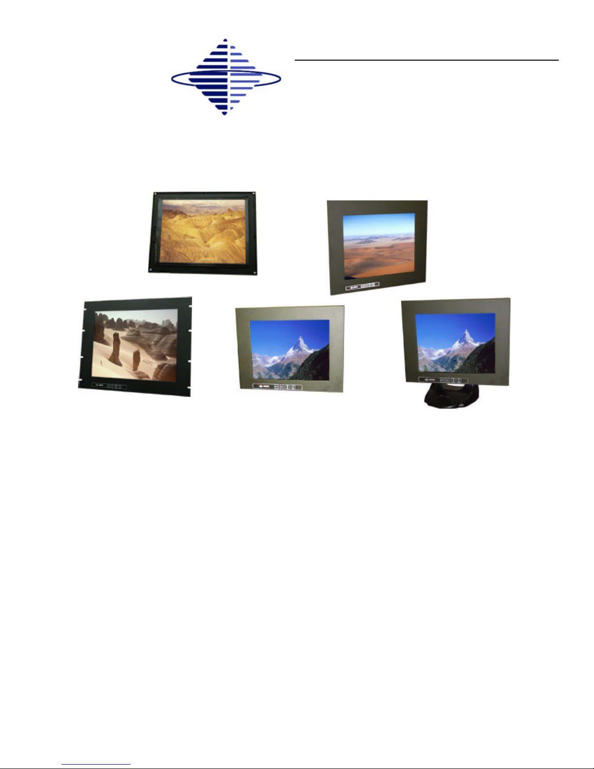
Your LCD monitor package will consist of the components listed below. Open shipping container and
lay all components on a flat clean surface.
⇒ VT150CC, VT150RC, VT150PC, VT150MC or VT150WC LCD Monitor
⇒ 15-PIN D-sub Video cable
⇒ AC power cord
⇒ User Manual or CD ROM
INSTALLATION
INSTALLATION
4
Section

VT150 ColorVue Series User Guide 150-032
4.3 Video Input Pin Assignment
This section describes the pin assignment of the LCD’s video connector.
HD15 Video Connector
The following table provides the pin numbers and corresponding pin
assignments for the HD-15 video connector.
5
1
15
Pin Connection
1 Red Video
2 Green Video
3 Blue Video
4 No Connection
5 Ground
6 Red Video Ground
7 Green Video Ground
8 Blue Video Ground
9 No Connection
10 Ground
11 No Connection
12 DDC data
13 Horizontal Sync
14 Vertical Sync
Pin assignments for the HD15 video connector
15 DDC Clock
Note:
The following figure is the view looking into the solder terminal end of the female connector.

VT150 ColorVue Series User Guide 150-032
TOUCH SCREEN
TOUCH SCREEN
6
5
Section
Touch screens are a common means to interface operator inputs to a system. The universal
standard of Windows GUI (Graphical User Interface) has significantly increased the use of
touch screens.
There are four main touch technologies. The technologies are resistive, surface acoustic
wave (SAW), capacitive, and infrared (IR). Each touch technology has advantages and
disadvantages based on different user applications.
All Vartech Systems displays configured with a touch screen are supplied with a CDROM
which includes user manuals, application software, and drivers for various operating systems.
Insert the supplied CDROM into a CDROM drive and follow the installation instructions that
will appear on the screen.
Limited technical support is available by contacting Vartech Systems customer support at
800-223-8050.
5.1 Introduction
5.2 Installation

VT150 ColorVue Series User Guide 150-032
The following table lists the better display quality modes that the LCD monitor provides. If the other
video modes are input, the monitor will stop working or display unsatisfactory picture quality.
VESA MODES
Mode Resolution Total
Horizontal
Nominal
Frequency
±0.5KHz
Vertical
Nominal
Frequency
±1Hz
Nominal Pixel
Clock (MHz)
DOS 720 x 400@70Hz 900 x 449 31.469 70.087 28.322
VGA
640 x 480@60Hz 800 x 525 31.469 59.940 25.175
640 x 480@72Hz 832 x 520 37.861 72.809 31.500
640 x 480@75Hz 840 x 500 37.500 75.000 31.500
SVGA
800 x 600@56Hz 1024 x 625 35.156 56.250 36.000
800 x 600@60Hz 1056 x 628 37.879 60.017 40.000
800 x 600@72Hz 1040 x 666 48.077 72.188 50.000
800 x 600@75Hz 1056 x 625 46.875 75.000 49.500
XGA
1024 x 768@60Hz 1344 x 804 48.363 60.004 65.000
1024 x 768@70Hz 1328 x 806 56.476 70.069 75.000
1024 x 768@75Hz 1312 x 800 60.023 75.029 78.750
Table 6.1 Applicable video timing - VESA Modes
7
DISPLAY TIMING
DISPLAY TIMING
6
Section

VT150 ColorVue Series User Guide 150-032
Display Timing Cont.
IBM MODES
Mode Resolution Total
Horizontal
Nominal
Frequency
±0.5KHz
Vertical
Nominal
Frequency
±1Hz
Nominal
Pixel Clock
(MHz)
EGA 640 x 350@70Hz 800 x 449 31.469 70.086 25.175
CGA 640 x 480@60Hz 800 x 449 31.469 70.086 25.175
DOS 800 x 600@56Hz 900 x 449 31.469 70.087 28.322
VGA 800 x 600@60Hz 800 x 525 31.469 59.940 25.275
XGA 800 x 600@72Hz 1304 x 798 57.515 72.100 75.000
Table 6.2 Applicable video timing - IBM Modes
8
MAC MODES
Mode Resolution Total
Horizontal
Nominal
Frequency
±0.5KHz
Vertical
Nominal
Frequency
±1Hz
Nominal
Pixel Clock
(MHz)
VGA 640 x 480@60Hz 800 x 525 31.469 59.940 25.175
640 x 480@67Hz 864 x 525 35.000 66.667 30.240
SVGA 832 x 624@75Hz 1152 x 667 49.725 74.551 57.283
XGA 1024 x 768@60Hz 1312 x 813 48.780 60.001 64.000
1024 x 768@75Hz 1328 x 804 60.241 74.927 80.000
Table 6.3 Applicable video timing - MAC Modes

VT150 ColorVue Series User Guide 150-032
9
7.1 Display Controls
DISPLAY CONTROLS
DISPLAY CONTROLS
7
Section
Button Description Function
Power
(Located on the rear of the monitor)
Press the power key to turn the monitor on.
Press it again to turn the monitor off
MENU Enter or exit the OSD adjustment menu.
Exit from the submenu back to the previous menu.
SELECT To confirm the current selection.
ADJUST UP To scroll up in menu or to increase value of selected item.
ADJUST DOWN
To scroll down in menu or to decrease value of selected
item.
MENU
SEL
7.2 Screen Adjustment Operation Procedure
1. Entering the screen adjustment
The setting switches are normally at stand-by. Push the MENU button once to display the
main menu of the screen adjustment. The adjustable items will be displayed in the main
menu.
2. Entering the settings
Use the Adjust and Adjust buttons to select the desired setting icon and push the
SELECT button to enter sub-menu.
3. Change the settings
After the sub-menu appears, use the Adjust and Adjust buttons to change the setting
values.
4. Save
After finishing the adjustment, push the SELECT button to memorize the setting.
5. Return & Exit the main menu
Exit the screen adjustment, push the ‘SELECT; button at the ‘EXIT; of “MISC MENU”. When
no operation is done around 60 sec (default OSD timeout), it goes back to the stand-by mode
and no more switching is accepted except MENU to restart the setting.

VT150 ColorVue Series User Guide 150-032
10
8.1 Main Menu
The OSD main menu (Figure 8-1) is displayed on screen when the MENU key pressed. The OSD
menu is a combination of graphic and text display. The column inside the OSD menu will show
information of input image. Second column beneath OSD menu shows the item selected.
The UP and DOWN keys are used to scroll through items within the menu. The selected item is
highlighted as the scrolling move along. The SELECT key is used to activated the highlighted item
during this state.
Figure 8.1 - OSD Main Menu
YES NO
SCREEN ADJUSTMENT
SCREEN ADJUSTMENT
8
Section

VT150 ColorVue Series User Guide 150-032
Symbol description Function
AUTO CONFIG
Auto Config is used to adjust the configuration of the phase ·
clock · vertical and horizontal position automatically. A
confirmation box is displayed to confirm the user selection. The
default selection in the box is “NO” and is highlighted by a red
bar. If the SELECT key is pressed, the main menu is
re-displayed and nothing is changed. When “YES” is selected,
automatic configuration is started. After the process is
completed successfully, a confirmation box, “Does this image
look correct”, is displayed. If image is correct, select “YES” to
exit confirmation box. If image isn’t correct, select “NO” to
PHASE item adjustment, and adjust the phase manually to the
best image quality.
BRIGHTNESS Brightness is used to setup the brightness of the panel.
CONTRAST Contrast is used to adjust image contrast.
COLOR
The main menu item “COLOR” is a sub-menu which contains
items to adjust the PC graphic imaging.
RED
Red is used to adjust the gain of the red channel in ADC.
GREEN
Green is used to adjust the gain of the green channel in ADC.
BLUE
Blue is used to adjust the gain of the blue channel in ADC.
BLACK LEVEL ADJUST
Black level adjust is used to adjust the black-level (zero level
offset) of the AD converters.
OSD Functions
11
8.2 OSD Adjusting and Controls

VT150 ColorVue Series User Guide 150-032
OSD Functions
Symbol description Function
POSITION
Setup the image position within the panel. There are two items:
H-POSITION · V-POSITION.
H-POSITION
H-Position is used to adjust the horizontal image position
manually.
A slider with current value is displayed.
V-POSITION
V-Position is used to adjust the vertical image position
manually.
A slider with current value is displayed.
IMAGE
Configure the image frequency.
PHASE
Phase is used to adjust the ADC sample pixel clock.
A slider with the current value is displayed. The range of phase
adjustment value is 0 to 100 for 0 to 360 degrees.
CLOCK
Clock is used to adjust the number of clocks (pixels) per line
(sample per line).
A slider with current value is displayed.
MISC MENU
Miscellaneous setting. There are three items: RESET · OSD
POSITION · SYSTEM INFO.
RESET
Reset is used to reload all factory default parameters.
OSD POSITION
OSD Position is used to setup the OSD menu position. The
OSD menu horizontal and vertical position is adjusted
separately. Each position adjustment item will bring up the
slider window. The maximum value of the sliders are based on
the size of the OSD menu.
SYSTEM INFO
The system info menu provides the user with detailed
information regarding the current input format and version.
(VERSION · V-FREQ · H-FREQ · RESOL).
12
Note:
If you don’t press any key for 45 seconds, the OSD will disappear by itself and the parameters will
not be saved.

VT150 ColorVue Series User Guide 150-032
13
8.3 How to use AUTO CONFIG Adjustment
This function can tune the parameters of PHASE · CLOCK · H-POSITION and V-POSITION.
Suggesting Adjustment Steps:
Step 1:
Enter the Windows 95/98 Shut-down frame. (Note the Wallpaper color CAN NOT be black.)
Step 2:
Enter OSD Main Menu and choose “AUTO CONFIG”, then press SELECT key. The picture
will auto-adjust by itself.
After 4 seconds, you can exit OSD and Shut-down frame.
Step3:
If you are still not satisfied with the picture quality, you can choose CONTRAST item in OSD
Main Menu and adjust it.
NOTE:
1. If you don’t like the effect of AUTO CONFIG adjustment, you can adjust PHASE, CLOCK,
H-POSITION and V-POSITION in OSD.
2. AUTO CONFIG adjustment can be used in Windows 95/98 except black background frame, but
the best effect is in the SHUT DOWN frame.
3. It is recommended to run “EDIT” program first, then do AUTO CONFIG adjustment in DOS mode.

VT150 ColorVue Series User Guide 150-032
14
Problem Troubleshooting Tip
No image on display screen 1. Check that power cord of the computer has been connected
securely into wall outlet or grounded extension cable or strip.
2. Check that power switch of the Display has been pressed.
3. Check that Video (Signal) Cable from the Display has been
securely and correctly connected.
4. Check that Video Card is firmly seated in card slot of Computer
motherboard.
5. Check that the video input from the Video Card falls within the
timing range (listed in the table of section 6) of the Display.
Abnormal image 1. Check that the video input from the Video Card falls within the
timing range (listed in the table of section 6) of the Display.
2. Check that Video (Signal) Cable from the Display has been
securely and correctly connected to the Video Connector at the
rear side of the Computer.
Colors of image on screen
are abnormal
1. Check that Video (Signal) Cable from the displays has been
securely and correctly connected to the 15-pin Video
Connector at the rear side of the computer.
Disturbances on Screen 1. OSD adjustment is incorrect. Please consult section 8 for OSD
screen adjustment procedures.
Troubleshooting Tips
TROUBLESHOOTING
TROUBLESHOOTING
9
Section

VT150 ColorVue Series User Guide 150-032
Cleaning
Occasionally clean the display panel and cabinet with a soft cloth dampened (not soaked)
with a mild (non-abrasive) glass cleaner. Keep turning a fresh side of the cloth toward the
screen surface to avoid scratching it with accumulated grit.
15
CLEANING AND MAINTENANCE
10
Section
Note:
The solvent should be applied only to the cloth, and not directly on the monitor screen.
Do not use paper products as they may scratch the surface. To minimize the risk of
abrasion, allow the screen to stand dry.
Special care should be taken when cleaning a touch screen or polycarbonate shield that is
installed over the screen. Abrasive and certain chemical cleaners can easily damage the
surface.
Never use alcoholic or ammoniac cleaners to clean the polycarbonate shield or a touch
screen.
Replacing a Line Cord
To avoid shock and fire hazards, the monitor’s power cord should be replaced if the
insulation becomes broken or if it develops a loose internal connection.
Other Maintenance
Qualified service personnel should perform all maintenance, except for the power cord
replacement described above.

VT150 ColorVue Series User Guide 150-032
MECHANICAL DRAWINGS
MECHANICAL DRAWINGS
11
Section
16
Model Description Page(s)
VT150PC 15.0” ColorVue Panel Mount Mechanical Drawing 17
VT150RC 15.0” ColorVue Rack Mount Mechanical Drawing 18
VT150WC 15.0” ColorVue Wall Mount Mechanical Drawing 19
VT150CC 15.0” ColorVue Chassis Mount Mechanical Drawing 20
Mechanical Drawings

VT150 ColorVue Series User Guide 150-032
21
VT150 ColorVue Specifications
LCD panel type 15.0” TFT
Resolution XGA 1024 x 768 Max.
Pixel dimension 0.297mm
LCD display color 16.7M Colors max.
OSD control
H/V Position, Clock, Phase, Auto Config, Expand,
Information, Recall, Edge Filter, Color, OSD Adjust,
Contrast, Brightness, Exit
Manual Control Menu, Select, Adjust ( ) Power
Viewing angle Left / Right: 60/60º max. Up / Down: 40/60º max.
Contrast ratio 300:1 typ.
Brightness 250cd/m² Typ.
Response time TR: 10ms typ.
TF: 10ms typ.
Active display area: VT150WC / T150MC
VT150PC / VT150RC / VT150CC
12.11” x 9.12” / 304.1mm x 228.1mm
12.03” x 9.09” / 305.5mm x 230.8mm
AC Input AC 100/240V, 50/60Hz
Input connector HD15
Input signal Video: Analog 0.7V p-p 75Ω
Sync; TTL Level, Positive/Negative, Separate Sync
Scan Frequency Horizontal: 31 to 60kHz
Vertical: 56 to 75Hz
Power Consumption 30 Watts Maximum
Power management VESA DPMS Compatible
Regulation Safety: DHHS, FCC A
Temperature Operation: 0 to 50ºC
Storage: -20 to 60ºC
Plug & Play DDC 2B
SPECIFICATIONS
SPECIFICATIONS
12
Section

VT150 ColorVue Series User Guide 150-032
150-032-007
09.10.04
VARTECH SYSTEMS INC.
HEADQUARTERS
11529 Sun Belt Ct.
Baton Rouge, Louisiana 70809
Toll-Free: 800.223.8050
International Phone: 001.225.298.0300
Fax: 225.297.2440
E-mail: sales@vartechsystems.com
www.vartechsystems.com
This manual suits for next models
4
Table of contents
Other VarTech Systems Industrial Monitor manuals