Varvel RC series Instructions for use

WORKING INSTRUCTIONS
AND MAINTENANCE
ACNH B.V.
http://www.wentellagers.nl

-2 -
VARVEL
IUM
WORKING INSTRUCTIONS
AND
MAINTENANCE
SPEED REDUCERS
RC - Helical Gearboxes
RD - Helical Gearboxes
RP - Helical Gearboxes
RS - Worm Gearboxes
RT - Worm Gearboxes
XA - Helical Gearboxes
VARIATORS
VR - Mechanical, dry friction
VR
D
RC
RD
RS
RT
RP
XA
ACNH B.V.
http://www.wentellagers.nl

-3 -
VARVEL
IUM
CONTENTS - GENERAL INFORMATION
CONTENTS
1 GENERAL INFORMATION 3
2 SAFETY WARNINGS 4
2.1 Product Operation 4
2.2 Prevalent Use 4
2.3 Transport 4
2.4 Long-Term Storage 4
2.5 Environmental Management 4
3 PRODUCT LAYOUT 4
3.1 Gearboxes Series RC 5
3.2 Gearboxes Series RD 6
3.3 Gearboxes Series RP/XA 7
3.4 Gearboxes Series RS 8
3.5 Gearboxes Series RT 9
3.6 Torque Limiter Option TLI 10
3.7 Variators Series VR 11
4 INSTALLATION 12
4.1 Tolerances 12
4.2 Precautions 12
4.3 Groundwork 12
4.4 Set up 12
4.5 Pinions, Couplings 12
4.6 Torque Arm 12
4.7 Painting 12
5 STARTING 13
5.1 Series RS, RT 13
5.2 Series RC, RD, RP, XA, VR 13
6 INSPECTIONS AND MAINTENANCE 14
6.1 Intervals 14
6.2 Maintenance Service 14
7 MALFUNCTIONING 15
7.1 Major Events 15
7.2 Customers Service 15
8 LUBRICANTS 16
8.1 Recommended Types 16
8.2 Quantity Series RC, RD 16
8.2 Quantity Series RP, RS, RT, XA 17
9 DIRETTIVE 94/9/CE - (ATEX) 18
DECLARATION OF CONFORMITY 23
1 GENERAL INFORMATION
Varvel speed reducers and variators are not in the field of application of the Machinery Directive, Article 1(2), and they
must be not put into service until the machinery into which they are to be incorporated, has been declared in conformity
with the provisions of Article 4(2), Annex II (B) of Machinery Directive 98/37/CE and, for Italy only, of DL 459/96.
Regular operation and the right to guarantee servicing request the observance of information contained in this manual that
must be read before the gearbox is put into service.
ACNH B.V.
http://www.wentellagers.nl

-4 -
VARVEL
IUM
SAFETY WARNINGS
PRODUCTS LAYOUT
2 SAFETY WARNINGS
2.1 Products Operation
During operation, outer surfaces of gearboxes and variators may warm up because of in motion parts and also by external
environmental conditions.
Everything referred to transport, stocking, assembling, setting up, starting and maintenance must be performed by trained
personnel and that follows this manual within specific national / regional regulations about safety and prevention of
accidents.
2.2 Prevalent Use
Gearboxes and variators referred to in this manual are destined to operate industrial applications and they correspond to
standards and regulations where applicable.
Performances and technical data are available in the unit’s nameplate and from the related documentation.
2.3 Transport
Carefully check the state of the goods at their receipt and immediately notify the possible damages to the carrier.
2.4 Long-Term Storage
Stocked units must be kept in dry warehouse and dust free.
For storage longer than 3 months, apply antioxidants on the shafts and machined surfaces paying special attention to
oilseal lips.
Storages longer than one year reduce bearing grease lifetime.
2.5 Environmental Management
In conformity with Environmental Certification ISO14001, we recommend the following to dispose of
• scrapped gearbox components: to deliver to authorised centres for metal object collection:
• drained oils and lubricants: to deliver to Exhausted Oil Centres;
• product accompanying packages (pallets, carton boxes, paper, plastic, etc.): to deliver into regeneration / recycling
circuits as far as possible, by delivering separate waste classes to authorised companies.
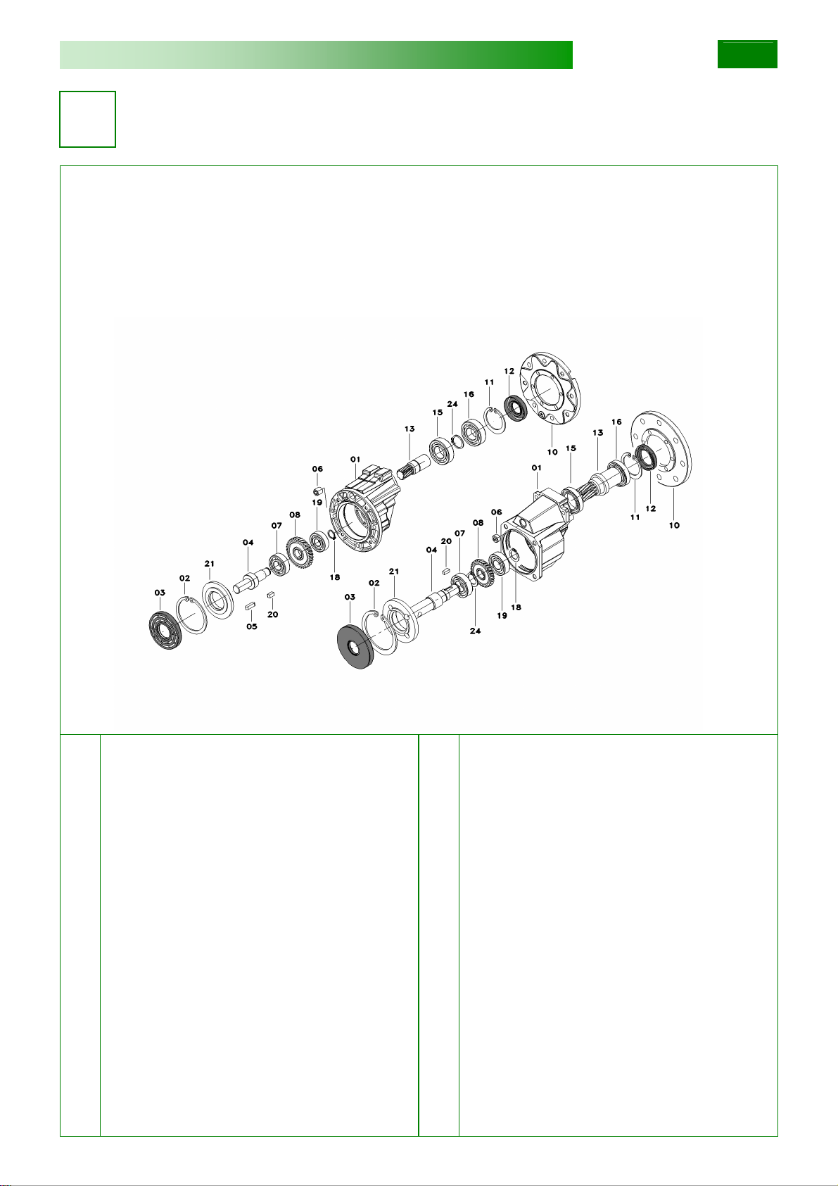
3 PRODUCTS LAYOUT
The following layouts supply a generic help in finding out the most significant parts of the products.
Various design executions of sizes, assembling versions, number of stages actually origin a variety of solutions and
therefore, we recommend to refer to the appropriate catalogue.
ACNH B.V.
http://www.wentellagers.nl

-5 -
VARVEL
IUM
PRODUCTS LAYOUT
3.1 Series RC
The layout shows the general structure of a two-stage foot-mounted helical gearbox type FRC.
The exact identification of spare parts is sent to the appropriate Catalogue MRC.
01 Oilseal 19 Bearing
02 Housing 20 Bearing
03 Key 21 Pinion
04 Output shaft 22 Key
05 Key 23 Gear
06 Bearing 24 Bearing
07 Spacer 26 Bearing
11 Gasket 27 Gear
13 Bearing 29 IEC input cover
15 Pinion 33 Hollow input
16 Key 35 Oilseal
17 Hollow input
ACNH B.V.
http://www.wentellagers.nl

-6 -
VARVEL
IUM
PRODUCTS LAYOUT
3.2 Series RD
The layout shows the general structure of a two-stage foot-mounted helical gearbox type FRD.
The exact identification of spare parts is sent to the appropriate Catalogue MRD.
01 Input cover 55 Spacer
02 Hollow input 65 Bearing
04 Pinion 66 Bearing
15 Bearing 67 Bearing
16 Bearing 68 Bearing
20 Oilseal 69 Oilseal
41 Gear 74 Circlip
50 Housing 81 Cover
52 Output shaft 82 Gasket
53 Pinion 85 Flange IEC
54 Gear
ACNH B.V.
http://www.wentellagers.nl

-7 -
VARVEL
IUM
PRODUCTS LAYOUT
3.3 Series RP and XA
The layout shows the general structure of a one-stage flange-mounted helical gearbox type FRP and FXA.
The exact identification of spare parts is sent to the appropriate Catalogue MRP or MXA.
01 Housing 12 Oilseal
02 Circlip 13 Pinion
03 Oilseal 15 Bearing
04 Output shaft 16 Bearing
06 Screw 18 Circlip
07 Bearing 19 Bearing
08 Gear 20 Key
10 Flange IEC 21 Adapter
11 Circlip 24 Circlip
FXA
FRP
ACNH B.V.
http://www.wentellagers.nl

-8 -
VARVEL
IUM
PRODUCTS LAYOUT
3.4 Series RS
The layout shows the general structure of a foot-mounted worm gearbox type FRS.
The exact identification of spare parts is sent to the appropriate Catalogue MRS.
01 Housing 63 Bearing
04 Side cover 80 Oilseal
07 Flange IEC 81 Oilseal
31 Worm wheel 82 Oilseal
50 Worm shaft 84 Oilseal RCA
60 Bearing 125 Circlip
61 Bearing 126 Circlip
62 Bearing
ACNH B.V.
http://www.wentellagers.nl

-9 -
VARVEL
IUM
PRODUCTS LAYOUT
3.5 Series RT
The layout shows the general structure of a foot-mounted worm gearbox type FRT.
The exact identification of spare parts is sent to the appropriate Catalogue MRT.
01 Housing 63 Bearing
04 Side cover 80 Oilseal
07 Flange IEC 81 Oilseal
31 Worm wheel 82 Oilseal
50 Worm shaft 84 Oilseal RCA
60 Bearing 125 Circlip
61 Bearing 126 Circlip
62 Bearing
ACNH B.V.
http://www.wentellagers.nl

-10 -
VARVEL
IUM
PRODUCTS LAYOUT
3.6 Torque Limiter Option TLI
The layout shows the general structure of a built-in torque limiter type TLI fitted inside a worm gearbox MRS or MRT.
The exact identification of spare parts is sent to the appropriate Catalogue TL.
01 Lock nut 08 Hollow output shaft
02 Bellville washer 10 Cover
03 Bush 60 Bearing
04 Oilseal 61 Bearing
05 Key 80 Oilseal
06 Spacer 81 Oilseal
07 Worm wheel
ACNH B.V.
http://www.wentellagers.nl

-11 -
VARVEL
IUM
PRODUCTS LAYOUT
3.7 Series VR
The layout shows the general structure of a flange-mounted variator without gearbox type FVR.
The exact identification of spare parts is sent to the appropriate Catalogue MVR.
02 Flange IEC 24 Oilseal
04 Seal plate 26 Output flange
05 Bearing 27 Spacer
06 Spacer 28 Bearing
07 Cone 30 Oilseal
09 Housing 31 Index scale
10 Cylindrical slide 33 Spring
14 Control hand wheel 34 Driving flange
15 Control-shaft lock 35 Friction ring
16 Control shaft 39 Cone support
19 Output shaft 40 Bellows seal
21 Bearing
24 23 22
21 20
19
25 26
27 28 27
28 29
30
31
18
32
33
32 34 35 37
38
36 41
42 43
44
39
08
40 04
03
0102
05
05
06
07
09
10
17
16
12
13
18
15
14
11
11
ACNH B.V.
http://www.wentellagers.nl

-12 -
VARVEL
IUM
INSTALLATION
4 INSTALLATION
4.1 Tolerances
Tolerances are recommended according to DIN 748 as follows
• Shafts: solid input or output ISO h6
hollow input ISO E8
hollow output ISO EH7
centre hole DIN 332, DR
• Flanges: spigot ISO h7
4.2 Precautions
Check that the unit to be put into service is rightly sized to perform the required function and that its mounting position
complies with the order. Such data are shown in the nameplate fitted on the unit.
Check mounting stability so that the unit operates without vibrations or overloads, or insert damping couplings or torque
limiters.
Care must be taken to ensure exact positioning and steadiness when handling the units to not origin damages to normal
operation of the unit.
When hoisting, use relevant locations of the housing or eyebolts if provided, or foot or flange holes.
Never hoist on any moving part (input or output shafts).
4.3 Groundwork
Clean carefully all the surfaces of shafts and flanges paying attention that the used product for cleaning does not came in
contact with sealing lips of oilseals to avoid any damage and lubricant leakages.
4.4 Set up
The unit may be connected for clockwise or counter-clockwise rotation.
Stop immediately the unit when unexpected running or noise occurs: if the part originating the anomaly is not identified,
other parts may be damaged with consequent difficulty in going back to the cause.
4.5 Pulleys, Pinions, Couplings
Bore tolerance F7 is recommended when fitting pulleys, pinions, couplings, etc. on the output shaft.
It is also recommended to not fit or extract with mallets or hammer hits to not damaging internal parts, but to use the shaft-
head threaded bore as reaction to fitting or extraction.
• Belt drives: the force imposed on the shaft due to belt tension to not exceed the maximum permissible radial force of
the unit.
• Chain drives: properly lubricate the chain drive and check that no pitch differences hinder its smooth running.
4.6 Torque arm
The torque arm Type BR (Series RS) or Type BT (Series RT) can rotate by 45°within the range 45°to 315°.
4.7 Painting
Carefully protect oilseals, coupling faces and shafts when units are re-painted.
ACNH B.V.
http://www.wentellagers.nl

-13 -
VARVEL
IUM
STARTING
5STARTING
5.1 Series RS, RT
The worm gearbox originates the following rotations of input and output shafts, with worm shaft upwards:
• inverse rotation
one-stage gearboxes (RS, RT);
• original rotation
helical/worm gearboxes (RA, TA);
• inverse rotation
two-stage gearboxes (RS/RS, RT/RT).
Worm shaft downwards: opposite situations.
5.2 Series RC, RD, RP, XA, VR
The helical gearbox and the variator originate the following rotations of input and output shafts:
• inverse rotation
odd-stage gearboxes (one, three, etc.)
and variators with odd-stages;;
• original rotation
even-stage gearboxes (two, four, etc.)
and variators without stages or even-stages.
6 INSPECTIONS AND MAINTENANCE
6.1 Intervals
Although the units are no-load run tested in the factory before despatch, it is advisable not to run them at maximum load
for the first 20-30 hours to allow proper running in.
For variators, run throughout the full speed range at reduced load before the full load is applied.
The units are delivered already filled with synthetic long-life oil: no servicing or refilling within the average lifetime of
15,000 hours for operation according to SF1.0.
Refer to the Catalogues as appropriate to the right definition of Service Factor.
Variators Series VR run dry and bearings are lifetime grease packed; thereore, there is no part needing periodical
maintenance, the friction ring replacement excepted on normal wearing conditions.
6.2 Maintenance Servicing
Units supplied without any oil plugs:
• Series RC (sizes 05, 10, 20, 30)
• Series RD (sizes 0, 1, 2, 3, 4)
• Series RP (size 71)
• Series RS (sizes 28, 40, 50, 60, 70, 85)
• Series RT (sizes 28, 40, 50, 60, 70, 85, 110)
• Series XA (sizes 63, 71, 80)
• Series VR (sizes 63, 71, 80, 90)
Units supplied with oil plugs:
• Series RC (sizes 40, 50, 60)
• Series RS (sizes 110, 130, 150)
Periodically check the state of seals and possible evidence of lubricant leakages.
If lubricant replacement or topping is required, do not mix with mineral based lubricants.
Variation section, dry running and with lifetime grease-packed bearings, does not require any periodic servicing, excepted
the friction ring replacement on normal wearing conditions.
ACNH B.V.
http://www.wentellagers.nl

-14 -
VARVEL
IUM
INSPECTIONS AND MAINTENANCE
6 INSPECTIONS AND MAINTENANCE
6.2 Maintenance Servicing
Observance of maintenance intervals is recommended to ensure the appropriate working conditions.
• GEARBOXES
According to working conditions:
Eliminate by means of a vacuum cleaner any dust accumulation thicker than 5 mm
Every 500 working hours or every month:
Oilseal visual check to monitoring any lubricant leakage.
Every 3000 working hours or every 6 months:
Oilseal check and replacement if considerably used.
Every 5 years:
Replace synthetic oil.
• VARIATORS
For variators VR only, please also consider the following prescriptions in addition to the above ones
According to working conditions:
Replace friction ring, if considerably used.
Every 3000 working hours or every 6 months:
Check output shaft angular play and oilseal and corrugated hood integrity.
Every 6000 working hours or every year:
Replace friction ring.
ACNH B.V.
http://www.wentellagers.nl

-15 -
VARVEL
IUM
MALFUNCTIONING
7 MALFUNCTIONING
7.1 Major Events
• Running noise, continuous Grinding sound: damaged bearing
Replace bearing & check the oil
Knocking sound: irregular gearing
Contact Customer Service
• Running noise, intermittent Foreign bodies in the oil
Contact Customer Service
Series VR - Damaged friction ring
Rectify the cause and replace friction ring.
See the following Section « Friction Ring Replacement »
• Oil leakages Damaged oilseal
(see also the following note) Replace oilseal
Loosen screws
Tighten the screws
Inner overpressure
Contact Customer Service
• No rotation of output shaft Internal connection cut off
Contact Customer Service
Series VR - Friction ring end of life
Replace the friction ring
See the following Section « Friction Ring Replacement »
Series VR - Contaminated friction ring
Clean carefully cone and ring working areas with solvent of similar
product.
See the following Section « Friction Ring Replacement »
Note: Oil evidence nearby the oilseal lip is a normal situation due to possible melting of lubricant used when fitting the
oilseal.
7.2 Customer Service
We recommend to always provide the Customer Service with the following information:
• Full data of name plate
• Type of application
• Duty cycle
• Circumstances of malfunctioning
•
ACNH B.V.
http://www.wentellagers.nl

-16 -
VARVEL
IUM
LUBRICANTS
8 LUBRICANTS
8.1 Recommended Types
The units are delivered already filled with synthetic long-life oil.
The safe operation of the units with ISO VG 320 grade lubricant is recommended in the ambient temperature range
-20 e +55 °C.
Temperatures beyond this range require specific recommendations for low or high temperatures to ask for the Customer
Service.
Type ISO VG
Synthetic Oil 320 Degol
GS 320 Energol
SG-XP320
Alphasyn
PG 320 Glycolube
320 Glygoyle
HE 320 Synlube
CLP 320 --- Tivela
SC 320
Food-grade
Synthetic Oil 320
460 Eural
Gear 460 --- Vitalube
GS 460 Gear Oil
FM 460
Mobil
DTE
FM 460 --- --- Cassida
Fluid GL
460
8.2 Quantity [litres]
RC 1c l1 l2 l3 2c l1 l2 l3 3c l1 l2 l3
RC105 0,05 0,65 0,05 RC205 0,13 0,15 0,15 RC305 0,17 0,30 0,30
RC110 0,10 0,13 0,10 RC210 0,17 0,25 0,17 RC310 0,25 0,50 0,35
RC120 0,17 0,25 0,17 RC220 0,50 0,60 0,50 RC320 0,60 0,80 0,60
RC130 0,30 0,50 0,30 RC230 0,70 1,15 0,80 RC330 1,15 1,50 1,15
RC140 0,60 1,15 0,60 RC240 1,15 2,25 2,00 RC340 1,50 3,00 2,25
RC150 1,50 2,25 1,50 RC250 2,25 4,40 4,00 RC350 3,75 6,00 5,00
RC160 3,00 4,40 3,00 RC260 6,00 8,80 8,00 RC360 8,00 10,00 8,80
1c - One stage
2c - Two stages
3c - Three stages
l1- B3, B6, B7, B8, B5
l2- V1, V5
l3- V3, V6
Refer to Catalogue MRC for detailed mounting positions
RD 2c H V 3c H V
RD02 0,40 0,50 RD03 0,40 0,50
RD12 0,50 0,70 RD13 0,50 0,70
RD22 0,80 1,00 RD23 0,80 1,00
RD32 1,30 1,80 RD33 1,60 2,10
RD42 2,20 3,00 RS43 2,20 3,40
2c - Two gear sets
3c - Three gear sets H - H1, H2, H3, H4
V - V5, V6
Refer to Catalogue MRD for detailed mounting positions
ACNH B.V.
http://www.wentellagers.nl

-17 -
VARVEL
IUM
LUBRICANTS
8.2 Quantity [litres]
RP FRP l
71 0,50
RS RS l RA l1 / l2 RS / RS
l3 / l4
28 0,03 63 / 40 0,04 / 0,10 28 / 28 0,03 / 0,03
40 0,10 63 / 50 0,04 / 0,15 28 / 40 0,03 / 0,10
50 0,15 63 / 60 0,04 / 0,25 28 / 50 0,03 / 0,15
60 0,25 71 / 50 0,06 / 0,15 28 / 60 0,03 / 0,25
70 0,35 71 / 60 0,06 / 0,25 40 / 70 0,10 / 0,35
85 0,63 71 / 70 0,06 / 0,35 40 / 85 0,10 / 0,63
110 1,50 71 / 85 0,06 / 0,63 50/110
0,15 / 1,50
130 2,75 80 / 60 0,10 / 0,25 60/130
0,25 / 2,75
150 4,40 80 / 70 0,10 / 0,35 70/150
0,35 / 4,40
80 / 85 0,10 / 0,63
80/110
0,10 / 1,50
130 0,20 / 2,75
150 0,20 / 4,40
l - Litres FRS
l1/ l2 - Litres FXA / FRS
l3/ l4- Litres FRS / FRS
RT RT l TA l1 / l2 RT / RT
l3 / l4
28 0,03 63 / 40 0,04 / 0,08 28 / 28 0,03 / 0,03
40 0,08 63 / 50 0,04 / 0,13 28 / 40 0,03 / 0,08
50 0,13 63 / 60 0,04 / 0,20 28 / 50 0,03 / 0,13
60 0,20 71 / 50 0,06 / 0,13 28 / 60 0,03 / 0,20
70 0,35 71 / 60 0,06 / 0,20 40 / 70 0,08 / 0,35
85 0,60 71 / 70 0,06 / 0,35 40 / 85 0,08 / 0,60
110 1,50 71 / 85 0,06 / 0,60 50/110
0,13 / 1,50
80 / 60 0,10 / 0,20
80 / 70 0,10 / 0,35
80 / 85 0,10 / 0,60
80/110
0,10 / 1,50
l - Litres FRT
l1/ l2- Litres FTA / FRT
l3/ l4- Litres FRT / FRT
XA FXA l
63 0,30
71 0,40
80 0,65
ACNH B.V.
http://www.wentellagers.nl

-18 -
VARVEL
IUM
DIRECTIVE 94/9/CE - (ATEX)
9 DIRECTIVE 94/9/CE
9.1 General Information 18
9.2 Prevalent Use 18
9.3 References 18
9.4 Temperature 19
9.5 Safety Instructions 19
9.6 ATEX Marking 21
9.7 Maintenance Servicing 21
9.8 Maintenance Schemes 22
DECLARATION OF CONFORMITY 23
9.1 General Information
Directive relates not only to electrical equipment, but also to all kind of machines and control components, separately or
jointly, for use in potentially explosive atmospheres.
The following recommendations, issued to operations in potentially explosive environment, are meant as specific
completion to general-purpose «Working instructions».
VARVEL-ATEX gearboxes and variators are manufactured with housings and covers of metallic material, incorporating
the transmission elements fitted on ball and roller bearings, with Viton oilseals on input and output shafts et with the
adequate oil quantity to assure the design operation.
9.2 Prevalent Use
VARVEL-ATEX gearboxes and variators are identified like « components », fundamental but without any autonomous
function to operate units and protection systems for production, transport, storage, measurement, control and conversion
of energy, or the processing of materials which are capable of causing an explosion through their own potential source of
ignition.
9.3 References
VARVEL-ATEX gearboxes and variators are designed and produced according to Directive 94/9/CE, and the following
standards
• EN 1127-1 - Explosion prevention and explosion protection
Fundamental notions and methodology.
• EN 13463-1 - Not electrical devices for potentially explosive atmospheres
Basic methods and required conditions.
• PrEN 13463-5 - Not electrical devices for potentially explosive atmospheres
Section 5: protection by construction safety « c ».
• PrEN 13463-6 - Not electrical devices for potentially explosive atmospheres
Section 6: protection by trigger source control « b ».
• PrEN 13463-8 - Not electrical devices for potentially explosive atmospheres
Section 8: protection by construction safety « k ».
ACNH B.V.
http://www.wentellagers.nl

-19 -
VARVEL
IUM
DIRECTIVE 94/9/CE - (ATEX)
9.4 Temperature
The units must be properly ventilated: ckeck that ventilation
temperature does not exceed 55 °C.
Measure housing temperature after 2 hours from start up
and check that the difference between measured
temperature (see the following sketch) and ambient
temperature does not exceed the max. value of 80 °C.
In such a case, immediately stop the unit and call for
Customer Service.
9.5 Safety Instructions
The electric motors and all the other elements, also enclosed the combinations of other power transmission elements to fit
at the input or at the output of the products VARVEL-ATEX, must be ATEX approved according the Directive 94/9/CE.
Temperature classes and max. temperature must be compatible with expected temperature limits of different product
types.
VARVEL gearboxes and variators must be installed and serviced according to installation and servicing standards for
classified environments against explosion hazard because of gas or dust presence (e.g. EN 60079-14, EN 60079-17, EN
50281-1-2 and any other acknowledged national standard).
In case of combustible dusts, it is mandatory the regular cleaning to avoid any accumulation of dust layers on product
surfaces.
The variators series VR (to run in category 2GD, or 3GD with overload possibilities) must be put into operation only when
fitted with a control device of output shaft rotation, made of impulse generator and speed control device (antiskid device),
that should be properly installed and calibrated by trained and qualified personnel.
Carefully check the speed control operation before starting the variator up.
Unique identification of the variators Series VR VARVEL-ATEX
is threaded hole (A) on the housing to install a pulse generator
(see drawing).
Speed control device and pulse generator are not included in
the standard configuaration of Variators VARVEL-ATEX.
Nevertheless, ask when ordering for the built in pulse
generator and output shaft speed control with the following
specifications.
Pulse Generator Speed Control Device
- Make: Pepperl+Fuchs,GmbH Pepperl+Fuchs, GmbH
- Type: NCB2-12GM35-N0 KFD2-DWB-Ex1.D
according to DIN 60947-5-6 (NAMUR) according to DIN 60947-5-6 (NAMUR)
with cable 2 m long …………
- Housing threaded hole: M12x1 …………
- ATEX Certification: PTB 00 ATEX 2048 X (II 1 G Eex ia IIC T6) TUV 99 ATEX 1408 (II 1 G Eex ia IIC)
ZELM 03 ATEX 0128 X (II 1 D Ex iaD 20 T..)
MRC MRD MRS
MRT
MVRMXAMRP
A
ACNH B.V.
http://www.wentellagers.nl

-20 -
VARVEL
IUM
DIRECTIVE 94/9/CE - (ATEX)
9.5 Safety Instructions
Pulse generator wiring must be made before
variator installation:
• rotate the variator output shaft until a pole piece (A)
of the friction ring holder is shown through the side
threaded hole of the housing;
• apply adeguate quantity of liquid locking threadsealing
on housing threaded hole M12x1, warning do not
introduce liquid sealing inside the housing;
• carefully screw the pulse generator to get in touch
with the pole piece;
• unscrew the pulse generator of 360°;
• apply adeguate quantity of liquid locking threadsealing
between enclosed lock-nut (B) and housing;
• secure pulse generator by screwing the equipped
lock-nut (B).
We recommned the utmost attention during the pulse generator adjustment because a mistake in screwing depth would
cause wrong impact with friction ring holder and the consequent damaging of both the parts and a mistake in pulse
generator sealing would cause the not ermetic sealing of variator and the IP66 protection level.
Speed control device adjustment
The above set up distance gives six pulses for each friction ring revolution.
Speed control device must be fitted and put into operation according to manufacturer’s documentation and installed
outside the potential esplosive atmosphere.
When installing:
• note working speed of variator on operation conditions;
• set stop speed of speed control device (according to working instructions of the used device) to 90% of the above
working speed;
• modify the stop speed according to working speed modifications.
Maximum operating time of speed control device must be shorther than 3 seconds: detect and remove the variator
slipping cause prior to switch the variator on again.
In case vibrations or anomalous noise occur during the variator starting, stop the variator and replace the friction ring
damaged by slipping (friction ring replacement at page 22).
The right wiring of the pulse generator to speed control device and to main control board is left to the sole responsibility of
the appointed technician.
A
B
ACNH B.V.
http://www.wentellagers.nl
This manual suits for next models
37
Table of contents
Other Varvel Engine manuals
Popular Engine manuals by other brands

Volvo Penta
Volvo Penta TAMD63L Instruction book

Moons'
Moons' Applied Motion Products SSM23Q/IP Hardware manual

Vetus
Vetus VF4.145 Operation manuals

Rotax
Rotax 915 iSc 3 A installation manual

Komatsu Utility
Komatsu Utility 3D82AE Series Shop Manual

YewdaleDefiant
YewdaleDefiant 980000 Programming instructions