Vauconsant MINI TROPIC User manual

1
Notice d’utilisation et d’entretien page 2
Schémas électriques page 3
Liste des pièces détachées page 4
Instructions of use and maintenance page 5
Electric diagrams page 6
Spare parts page 7
Benutzungs und Wartungsnotiz Seite 8
Schaltplan Seite 9
Ersatzteilliste Seite 10
Rue Charles Hermite Z.I. des Sables BP 59
54110 Dombasle sur Meurthe France
tel : (+33) 03 83 45 82 82 - fax : (+33) 03 83 45 82 93
Etuve mobile MINI TROPIC
MINI-TROPIC Movable Hot Cupboard
MINI TROPIC Warmer Schrank auf Rollen
Notice N°CC305 - mise à jour le 10 août 2006

2
Notice d’utilisation et d’entretien
GENERALITES
Eléments chauffants
Un bloc de résistances circulaires blindées acier inox, d’une
puissance totale de 1500 W, avec circulation d’air par ventilateur.
Organes de commande
Commande simultanée de la ventilation et du chauffage par
thermostat avec voyant de contrôle, température réglable de 30 à
110°C.
Arrêt de la chauffe à l’ouverture de la porte.
Affichage de la température d’utilisation par thermomètre
mécanique.
Ensemble disposé sur un tableau de commande en haut de
l’étuve.
Protection
Par fusible intégré à la prise, calibre 10A.
INSTALLATION
Raccordement électrique
Avant de raccorder, contrôler impérativement que la
tension existante est la même que celle mentionnée sur la
plaque signalétique de notre meuble.
La ligne électrique qui alimente le meuble doit être protégée par
un disjoncteur différentiel au tableau général.
Utiliser le cordon d’alimentation fourni avec l’étuve mobile,
brancher celui-ci sur la prise mâle située sur l’arrière de l’étuve
mobile.
Brancher le cordon d’alimentation sur une prise de courant
10/16A 230 V + Terre.
UTILISATION
Mise en service
Mise en route trente minutes avant le service.
Les bacs gastronormes doivent être utilisés avec un couvercle.
Les barquettes doivent être operculées.
Tourner le bouton du thermostat vers la droite sur la position
110°C. Cette position permet de maintenir la température des
aliments au dessus de +65°C, qui est la température minimum
définie par les services d’hygiène.
Pour pouvoir tenir cette température, il est indispensable
d’amener les aliments à une température comprise entre +70 et
+80°C.
Nettoyage
A effectuer quand l’étuve chauffante ventilée est à l’arrêt (
appareil hors tension ), et le cordon d’alimentation débranché.
Nettoyer deux fois par semaine les parties extérieures et
l’intérieur de l’étuve.
Enlever le déflecteur d’air situé dans le fond de l’étuve
Utiliser une éponge avec de l’eau savonneuse ou des produits
spéciaux pour le nettoyage des aciers inoxydables. Rincer avec de
l’eau. Essuyer avec des chiffons, en coton de préférence.
Ne pas utiliser de produits pour le nettoyage des sols, des acides
même dilués, des produits chlorés ou décapants, qui pourrais
provoquer une corrosion de l’acier inoxydable.
Ne pas utiliser de produits abrasifs ( paille de fer, etc…).
Ne pas laver le meuble au jet d’eau, canon à mousse ou
nettoyeur haute pression.
Le nettoyage terminé, remettre en place le déflecteur d’air.
ENTRETIEN
L’installateur doit vérifier les connexions électriques à la mise
en service du meuble ( après une fois par an ).
FICHE DE MAINTENANCE
Pour accéder aux parties actives et au câblage électrique de
l’étuve, suivre les indications du dessin ci-dessous.
LEGENDE DE LA FICHE DE MAINTENANCE
Repère Désignation
1 Résistance 1500 W
2
V
entilateur
3 Prise électrique avec fusible 10 A et cordon d’alimentation
4 Thermostat sécurité 130 °
5 Thermomètre mécanique
6 Thermostat et interrupteur
7
V
oyant orange de contrôle
8 Interrupteur de fin de course pour étuve à porte

3
Schéma électrique
Etuve mobile à porte
Schéma électrique
Etuve mobile à trois tiroirs
Légende des schémas électriques
Fc Interrupteur fin de course ouverture de la porte T Thermostat
Q Socle prise avec fusible Ts Thermostat de sécurité
R Résistance V
V
oyant étuve en chauffe
S Marche / Arrêt chauffe de l’étuve Vt
V
entilateur

4
Liste des pièces détachées
Code Désignation
Etuve à porte
code 32508 Etuve à tiroirs
code 32608
Accessoires
02.1015 Charnière porte FERMOD X
02.1110 Loqueteau porte FERMOD X
02.1408 Poignée de tiroir X
02.3210 Roulette à platine pivotante 100 mm X X
02.3220 Roulette à platine pivotante à frein 100 mm X X
02.4055 Paire de coulisses 2 éléments long 450 X
03.3100 Cadre joint porte X
06.3020 Thermomètre mécanique à encastrer X X
Equipement électrique
06.0682 Résistances circulaires 1,5 kW 230 V X X
06.1040 Fin de course pour porte X
06.1180 Bouton noir pour thermostat X X
06.1188 Thermostat de sécurité X X
06.1202 Thermostat tripolaire 30 à 110°C X X
06.1225 Interrupteur pour thermostat X X
06.1600
V
oyant orange X X
06.2078 Cordon d’alimentation X X
06.2080 Socle prise avec fusible intégré X X
06.3505
V
entilateur X X
Service pièces détachées
Francis LECOMTE
Téléphone : 03 83 45 82 78
Fax : 03 83 45 82 75

5
Instructions of use and maintenance
GENERAL POINTS
Heating elements
A block of circular stainless stell heating elements steel, of a total
power of 1500 W, with circulation of air by ventilator.
Controls
Simultaneous order of the ventilation and the heater by
thermostat with seeing of control, adjustable temperature of 30
to 110°C.
Stop of the heating in the opening of the door.
Display of the temperature of use by mechanical
thermometer.
Set arranged on a control panel in the top of the steam room.
Protection
By main power fuse holder, integrate into the plug.
INSTALLATION
Electric connection
Before plugging, imperatively control the voltage rating:
it should be the same voltage as indicated on the
cupboard.
The electric power line providing the cupboard should be
protected by a differential circuit breaker located on the main
electric distribution panel.
Use the twist supplied with the cupboard, to connect this one on
the plug situated on the back of the cupboard.
Connect the twist on a socket 10 / 16A 230 V + Earth.
HOW TO USE
To put into service
Started thirty minutes before the service.
The gastronorm trays should be used with cover.
The boat-shaped pastry should be operculated.
Turn to the right the thermostat knob, adjust to +100°C. At
this setting, the food’s temperature is maintened above +65°C
which is the minimum temperature defined by Health
departments.
To be capable to maintain this temperature, the food’s
temperature should be raised to be between +70°C and +80°C.
Cleaning
To be performed when the cupboard is shut down ( the unit
is turned off ) and the strand is unplugged.
To wash twice a week the unit and inside the cupboard.
Remove the deflector of ventilation, located in the back of the
cupboard.
Use a sponge moistened with soapy water or products as
cream products.Rince off with water. Dry preferably with lint-
free cotton cloths.
Do not use washing product for the floor, acid even diluted
with water, chlorinated or scrouring solution products, which
make corrosion of stainless steel.
Do not use abrasive products ( steel wool, etc…°.
Do not clean the unit by spraying with water, using a soap
gun, or under high pressure jets.
When the cleaning is finished, put back the deflector of
ventilation.
MAINTENANCE
The installer should check all the electric connections during
the initial start up of the cupboard ( and then once a year).
INDEX OF MAINTENANCE
To reach the active parts and the electric cabling of the
cupboard, to follow the indications of the drawing below.
CAPTION OF INDEX OF MAINTENANCE
Mark Designation
1 Heating element 1500 W
2
V
entilator
3 Plug-in with 10A fuse and twist
4 Safety thermostat 130 °C
5 Mechanical thermometer
6 Thermostat and switch On/Off
7 Orange indicator
8 Switch at the end of running opening of the door
REMOVABLE TOP
1 ↔TO PUSH
2 ↔TO RAISE
DISMANTLING OF THE BACK
TO REMOVE THE 6 SCREWS OF FIXATION

6
Electric diagram / Hot cupboard with door
Electric diagram / Hot cupboard with three drawers
Caption diagram electric
Fc Switch at the end of running opening of the door T Thermostat
Q Plug in with fuse Ts Safety thermostat
R Heating element V Cupboard heating indicator
S Cupboard switch On/Off Vt
V
entilator

7
SPARE PARTS
Code Désignation
Cupboard with
door
code 32508
Cupboard with
three drawers
code 32608
Accessories
02.1015 FERMOD hinge for door X
02.1110 FERMOD latch for door X
02.1408 Handle of drawer X
02.3210 Caster platinizes swivelling 100 mm X X
02.3220 Caster platinizes swivelling 100 mm with brake X X
02.4055 Pair of wings 2 elements length 450 X
03.3100 Joint frame for door X
06.3020 Mechanical thermometer X X
Electric equipment
06.0682 Circular heating element 1,5 kW 230 V X X
06.1040 Switch at the end of running X
06.1180 Black PVC knob 43 mm X X
06.1188 Safety thermostat X X
06.1202 Tripolar thermostat 30 to 110°C X X
06.1225 Switch for thermostat X X
06.1600 Orange indicator X X
06.2078 Twist X X
06.2080 Plug in with fuse X X
06.3505
V
entilator X X

8
Benutzungs und Wartungsnotiz
ALLGEMEINE BESCHREIBUNG
Heizelemente
Block mit drei verdichteten kreisförmigen CNS-Widerständen.
Gesamtleistung 1500 W; Luftzirkulation durch Ventilator.
Steuerelemente
Gleichzeitige Steuerung für die Ventilation und die Beheizung
durch Thermostat mit Kontrollleuchte.
Automatisches Aussetzen der Heizung beim Öffnen der Tür.
Temperaturregelung von + 30°C bis + 110°C.
Anzeige der Benutzungstemperatur durch mechanischen
Thermometer.
Sämtliche Steuerungen auf einem Bedienpaneel im oberen Teil
des Schranks.
Schutz
Durch Sicherung in der Steckdose integriert (10 A).
INSTALLATION
Elektrischer Anschluss
Vor dem Anschließen ist unbedingt zu prüfen, dass die
Netzspannung mit der auf dem Erkennungsschild ange-
gebenen Spannung übereinstimmt.
Die elektrische Zuleitung zum Gerät muss mit einer
separaten Differentialsicherung im Schaltschrank
abgesichert werden.
Verwenden Sie das mit dem Schrank gelieferte elektrische
Kabel, und schlieβen Sie es dann auf den männlichen Schalter
(hinteres Teil des Schranks) an.
Anschluss: mit einer Steckdose 10/16 A230 V mit Erdung.
GEBRAUCHSANWEISUNG
Inbetriebnahme
Inbetriebnahme eine halbe Stunde vor
Ausgabebeginn.
Die Gastronorm-Behälter GN 1/1 sind mit den Deckeln zu
verwenden. Die Speisenschalen müssen versiegelt bleiben.
Drehen Sie den Thermostatsknopf nach rechts bis +110°C
auf. Diese Einstellung ermöglicht eine Temperatureinhaltung
der Speisen oberhalb von +65°C, entsprechend der von den
Gesundheitsbehörden verlangten Mindesttemperatur.
Damit diese Mindesttemperatur ständig eingehalten werden
kann, müssen Speisen mit einer Minimaltemperatur zwischen
+70°C u. + 80°C hingestellt werden.
Reinigung
Vor dem Reinigen ist das Gerät auszuschalten, das elektrische
Kabel muss aus der Steckdose gezogen sein.
Das Gerät ist zweimal wöchentlich zu reinigen (Auβen- u.
Innenteile.) Nehmen Sie das im Boden des Schranks
befindliche Luftleitblech ab.
Benutzen Sie einen Schwamm mit Seifenwasser oder Spezial-
reiniger für CNS. Spülen Sie mit Wasser ab und trocknen Sie
vorzugsweise mit Baumwolltüchern nach.
Verwenden Sie keine Bodenputzmittel, chlorhaltige oder
ätzende Mittel (auch nicht verdünnt) die zur Rostbildung auf
dem CNS führen können.
Verwenden Sie keine Scheuermittel (Stahlwolle usw…)
Kratzen Sie nicht mit scharfen Gegenständen ab.
Keine Reinigung mit Wasserschlauch, Schaumpistole
oder Hochdruckreiniger.
Nach dem Reinigen setzen Sie das Luftleitblech wieder ein.
WARTUNG
Vor der ersten Inbetriebnahme sind alle elektrische
Anschlüsse zu prüfen( danach einmal jährlich ).
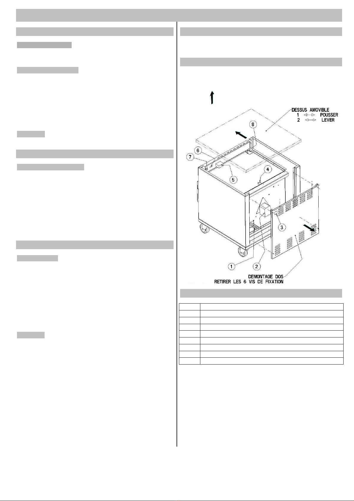
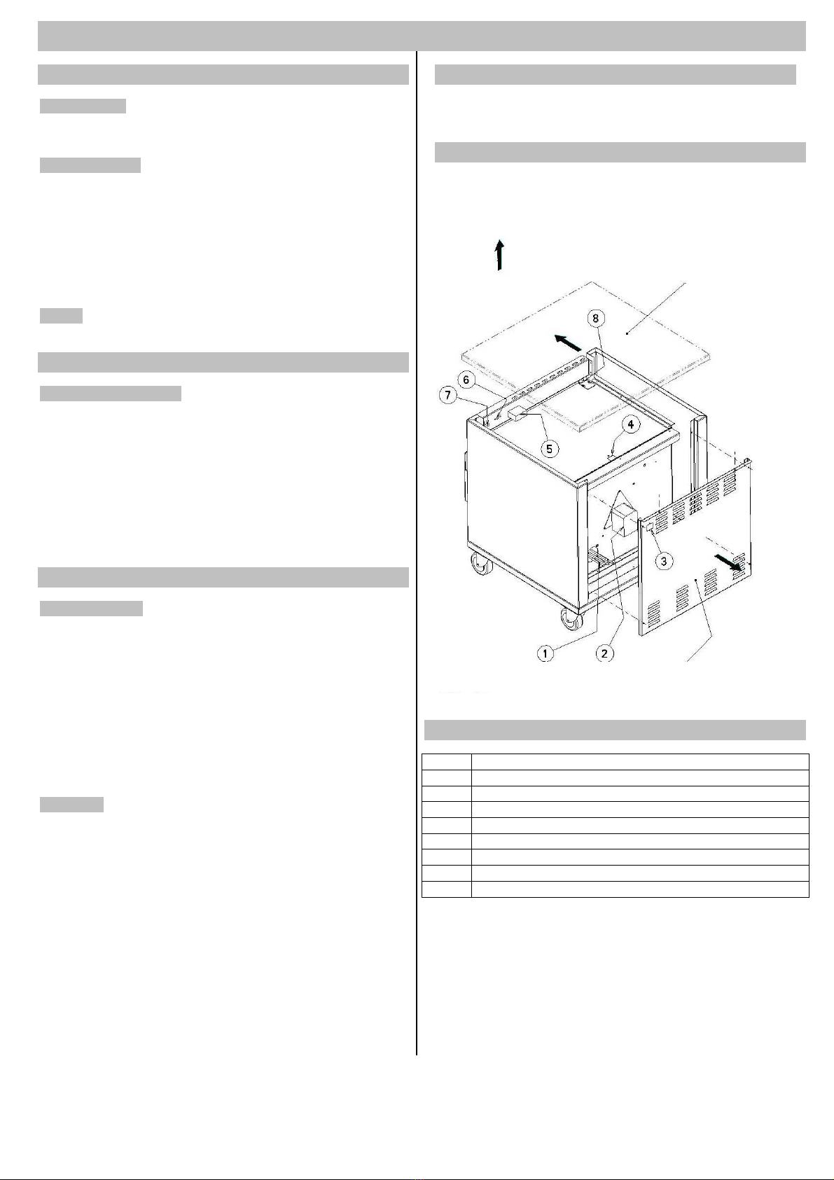
WARTUNGSANGABEN
Um an die aktiven Elemente und an die Verkabelung des
Geräts zu gelangen, folgen Sie bitte den in der nachtehenden
Zeichnung gegebenen Anweisungen.
LEGENDE DER WARTUNGSZEICHNUNG
Ziffer Bezeichnung
1 Widerstand 1500 W
2
V
entilator
3 Steckdose mit Sicherung 10 A und elektrisches Kabel
4 Sicherheitsthermostat 130 °C
5 Mechanischer Thermometer
6 Thermostat und Schalter
7 Orange Kontrollleuchte
8 Schalter Laufanschlag für Schrank mit Tür.
DEN RÜCKEN ZURÜCKZUZIEHEN
DIE 6 BEFESTIGUNGSSCHRAUBEN
ABNEHMBARE OBERFLÄCHE
1 ↔ZU DRÜCKEN
2 ↔AUFZUHEBEN

9
Schaltplan Heizschrank mit Tür
Schaltplan Heizschrank mit drei Schubladen
Legende der Schaltpläne
Fc Schalter Laufanschlag; Öffnen der Tür T Thermostat
Q Sockel Steckdose mit Sicherung Ts Sicherheitsthermostat
R Widerstand V Kontrollleuchte Beheizung
S Ein / Aus Beheizung Vt
V
entilator

10
Ersatzteile
Art Nr. Bezeichnung Schrank mit Tür
32508
Schrank mit
Schubladen
32608
Zubehör
02.1015 FERMOD - Türscharnier X
02.1110 FERMOD - Türriegel X
02.1408 Schubladengriff X
02.3210 Drehrolle 100 mm ∅, mit Befestigungsplatte X X
02.3220 Drehrolle 100 mm ∅, mit Befestigungsplatte u. Bremse X X
02.4055 Paar schiebevorrichtungen 2 Stücke 450 mm lang X
03.3100 Türabdichtung X
06.3020 Machanischer Thermometer zum Einbauen X X
Elektrische Ausstattung
06.0682 Kreisförmiger Widerstand 1,5 kW 230 V X X
06.1040 Laufanschlag für Tür X
06.1180 Schwarzer Drehknopf für Thermostat X X
06.1188 Sicherheitsthermostat X X
06.1202 Thermostat dreipolig +30°C bis +110°C X X
06.1225 Schalter für thermostat X X
06.1600 Orange Kontrollleuchte X X
06.2078 Elektrisches Kabel X X
06.2080 Sockel Steckdose mit eingebauer Sicherung X X
06.3505
V
entilator X X
Table of contents
Languages:
Other Vauconsant Commercial Food Equipment manuals
Popular Commercial Food Equipment manuals by other brands

Redfox
Redfox BR-90/80 G Instructions for installation and use

Keysight Technologies
Keysight Technologies 11636C Operating and service manual

Skope
Skope OD330N Service manual

Scharfen
Scharfen TC 11 operating instructions

Lotus
Lotus MFM-68EM Installation and operating instructions

Casselin
Casselin CBIN manual