Taylor C712 Installation guide

Model C712


Table of Contents
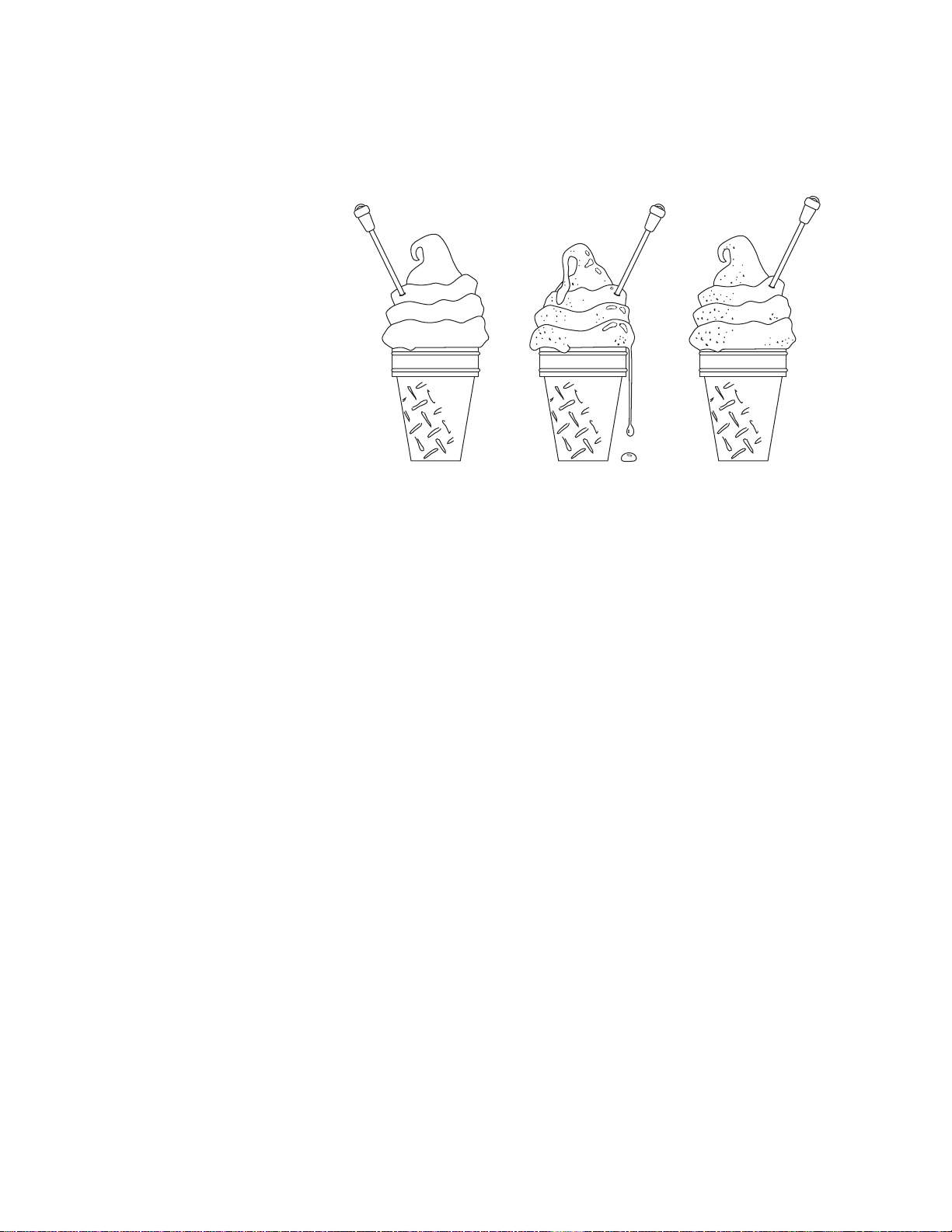
Product. . . . . . . . . . . . . . . . . . . . . . . . . . . . . . . . . . . . . . . . . . . . . . . . . . . . . . . . . . . .2
Temperature. . . . . . . . . . . . . . . . . . . . . . . . . . . . . . . . . . . . . . . . . . . . . . . . . . . . . .2
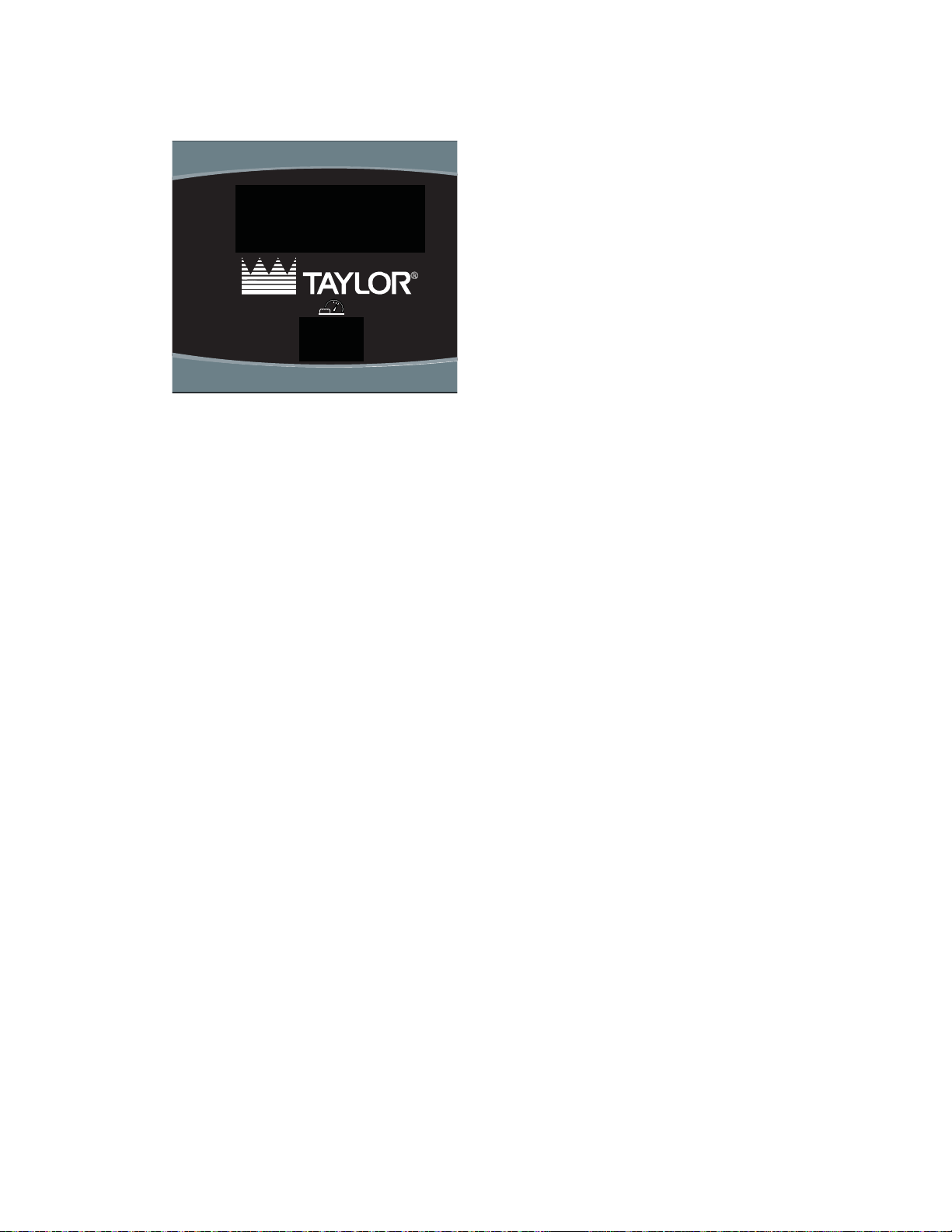
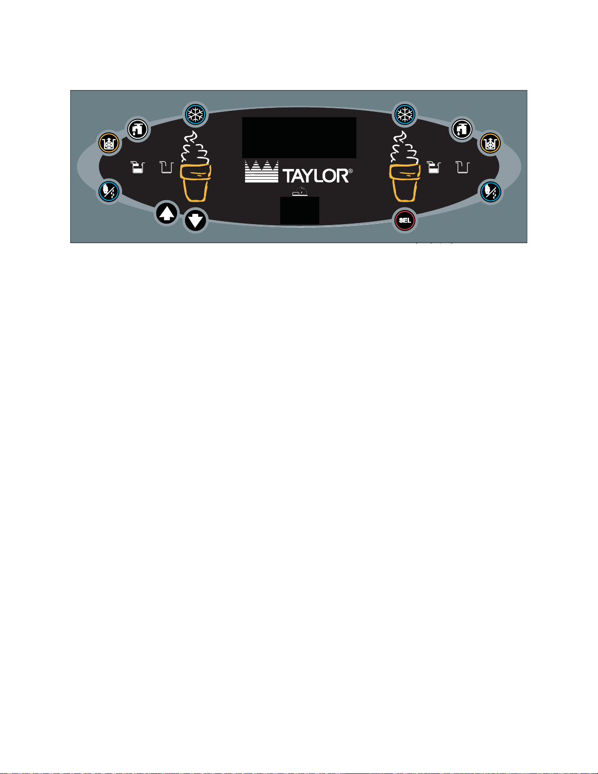
Control . . . . . . . . . . . . . . . . . . . . . . . . . . . . . . . . . . . . . . . . . . . . . . . . . . . . . . . . . . . .3
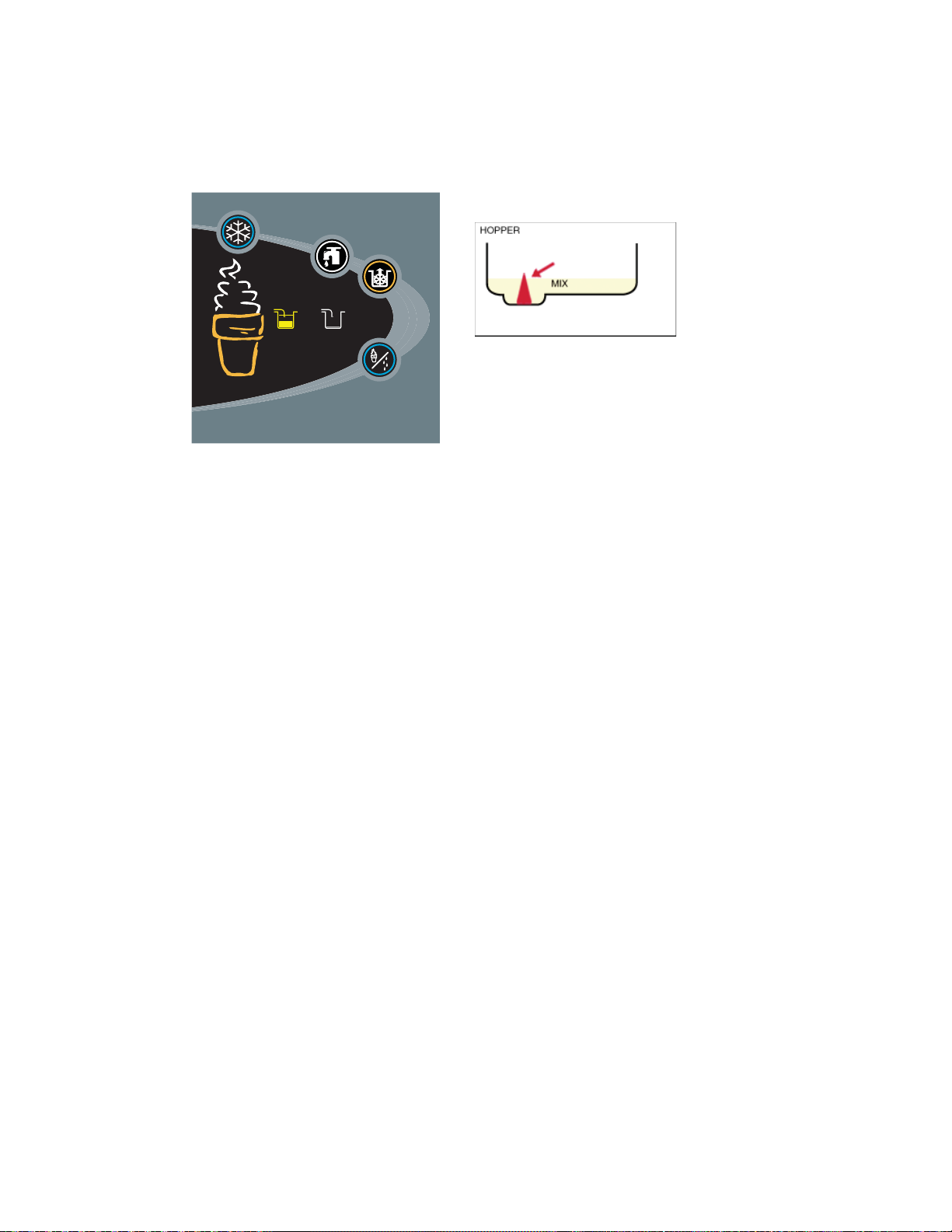
Mix Low . . . . . . . . . . . . . . . . . . . . . . . . . . . . . . . . . . . . . . . . . . . . . . . . . . . . . . . . .3
Mix Out . . . . . . . . . . . . . . . . . . . . . . . . . . . . . . . . . . . . . . . . . . . . . . . . . . . . . . . . .4
Brush Clean Counter. . . . . . . . . . . . . . . . . . . . . . . . . . . . . . . . . . . . . . . . . . . . . . .5
Accessing Data . . . . . . . . . . . . . . . . . . . . . . . . . . . . . . . . . . . . . . . . . . . . . . . . . . .6
Menu Simulator . . . . . . . . . . . . . . . . . . . . . . . . . . . . . . . . . . . . . . . . . . . . . . . . . . .7
Operating Procedures . . . . . . . . . . . . . . . . . . . . . . . . . . . . . . . . . . . . . . . . . . . . . . .8
Draw Handle Calibration . . . . . . . . . . . . . . . . . . . . . . . . . . . . . . . . . . . . . . . . . . . .8
Assembly. . . . . . . . . . . . . . . . . . . . . . . . . . . . . . . . . . . . . . . . . . . . . . . . . . . . . . . .9
Freezing Cylinder Reset . . . . . . . . . . . . . . . . . . . . . . . . . . . . . . . . . . . . . . . . . . .11
Freezing Cylinder Checklist. . . . . . . . . . . . . . . . . . . . . . . . . . . . . . . . . . . . . . . . .12
Pump Assembly. . . . . . . . . . . . . . . . . . . . . . . . . . . . . . . . . . . . . . . . . . . . . . . . . .13
Pump Reset. . . . . . . . . . . . . . . . . . . . . . . . . . . . . . . . . . . . . . . . . . . . . . . . . . . . .14
Pump Checklist . . . . . . . . . . . . . . . . . . . . . . . . . . . . . . . . . . . . . . . . . . . . . . . . . .15
Sanitizing. . . . . . . . . . . . . . . . . . . . . . . . . . . . . . . . . . . . . . . . . . . . . . . . . . . . . . .16
Priming. . . . . . . . . . . . . . . . . . . . . . . . . . . . . . . . . . . . . . . . . . . . . . . . . . . . . . . . .17
Manual Brush Cleaning . . . . . . . . . . . . . . . . . . . . . . . . . . . . . . . . . . . . . . . . . . . .18
Troubleshooting . . . . . . . . . . . . . . . . . . . . . . . . . . . . . . . . . . . . . . . . . . . . . . . . . . .21
Hopper. . . . . . . . . . . . . . . . . . . . . . . . . . . . . . . . . . . . . . . . . . . . . . . . . . . . . . . . .21
LCD . . . . . . . . . . . . . . . . . . . . . . . . . . . . . . . . . . . . . . . . . . . . . . . . . . . . . . . . . . .21
Cylinder . . . . . . . . . . . . . . . . . . . . . . . . . . . . . . . . . . . . . . . . . . . . . . . . . . . . . . . .22
Door. . . . . . . . . . . . . . . . . . . . . . . . . . . . . . . . . . . . . . . . . . . . . . . . . . . . . . . . . . .23
Drip Pan. . . . . . . . . . . . . . . . . . . . . . . . . . . . . . . . . . . . . . . . . . . . . . . . . . . . . . . .24
Product . . . . . . . . . . . . . . . . . . . . . . . . . . . . . . . . . . . . . . . . . . . . . . . . . . . . . . . .25
Parts. . . . . . . . . . . . . . . . . . . . . . . . . . . . . . . . . . . . . . . . . . . . . . . . . . . . . . . . . . . . .26
Three Months Parts Replacement. . . . . . . . . . . . . . . . . . . . . . . . . . . . . . . . . . . .26
Six Months Parts Replacement . . . . . . . . . . . . . . . . . . . . . . . . . . . . . . . . . . . . . .27
Quiz . . . . . . . . . . . . . . . . . . . . . . . . . . . . . . . . . . . . . . . . . . . . . . . . . . . . . . . . . . . . .28
Rev. 2012hz03.07

C712 Operator Training -2-
Product
Temperature
Temperature is a
key factor in product
appearance.
The recommended
temperatures are:
Soft Serve: 16 to 18°F
(-7.8 to -8.8°C)
However, you can see in
the illustration that a soft
serve cone at the proper
temperature can still
appear drippy. 18°F
-7.8°C
18°F
-7.8°C 15°F
-9.4°C
A seven minute freeze-down time is necessary to make frozen product (18° F/-7.8° C) from liquid
mix (40° F/4.4°C).
Once the product is frozen, subsequent refrigeration cycles are necessary. The machine will cease
refrigeration for 10 minutes to maintain servable product during the day.
Product that is overbeaten is “broken down.” Broken down product is caused by longer than
normal freeze times.
Longer than normal freeze times can be caused by:
• Worn scraper blades
• Insufficient air space around the freezer
• Dirty condensers or air filters
• Loss of refrigerant (refrigerant leak)
___________________________________________________________________________
___________________________________________________________________________
___________________________________________________________________________
___________________________________________________________________________
___________________________________________________________________________

C712 Operator Training -3-
Control
Mix Low
The Cause
Solution
Open the hopper lid and fill the hopper
with new mix. The indicator light will turn
off after the mix covers the top sensor.
Make sure the mix low indicators on the front of the machine are off to assure successful operation
and product dispensing.
Milkstone build-up can cause an erroneous mix low indication.
___________________________________________________________________________
___________________________________________________________________________
___________________________________________________________________________
___________________________________________________________________________
___________________________________________________________________________
___________________________________________________________________________
___________________________________________________________________________
___________________________________________________________________________
___________________________________________________________________________
___________________________________________________________________________
___________________________________________________________________________
___________________________________________________________________________
___________________________________________________________________________

C712 Operator Training -4-
Mix Out
The Cause
Solution
Open the hopper lid and fill the hopper
with new mix. The mix out indicator
light will turn off after the mix covers the
bottom sensor. The mix low indicator light
will turn off after the mix covers the top
sensor.
Note: There may be a beeping sound
when a mix light is lit.
When the machine experiences a mix out condition, the machine enters the STANDBY mode of
operation.
___________________________________________________________________________
___________________________________________________________________________
___________________________________________________________________________
___________________________________________________________________________
___________________________________________________________________________
___________________________________________________________________________
___________________________________________________________________________
___________________________________________________________________________
___________________________________________________________________________
___________________________________________________________________________
___________________________________________________________________________
___________________________________________________________________________

C712 Operator Training -5-
Brush Clean Counter
®
02
The Brush Clean Counter will display the
number of hours since the freezer was
last brush cleaned.
After hour 99, the brush clean counter will change to a letter and a number (example: A0, A1...B0, B1, etc.).
___________________________________________________________________________
___________________________________________________________________________
___________________________________________________________________________
___________________________________________________________________________
___________________________________________________________________________
___________________________________________________________________________
___________________________________________________________________________
___________________________________________________________________________
___________________________________________________________________________
___________________________________________________________________________
___________________________________________________________________________
___________________________________________________________________________
___________________________________________________________________________

C712 Operator Training -6-
Accessing Data
®
Pump Symbol: Used to turn on the pump.
Wash Symbol: Used to enter the WASH mode.
Auto Symbol: Sets the machine in AUTO mode.
Mix Low Symbol: Illuminates when the mix hopper has a low supply of mix and should be
refilled as soon as possible.
Mix Out Symbol: Illuminates when the mix hopper has an insufficient supply of mix to
operate the freezer. The AUTO mode will be locked out and the machine will be placed in
the STANDBY mode.
Standby Symbol: Indicates when the machine is in the STANDBY mode.
Select (SEL) Symbol: Used to advance the cursor position and select options in the menu.
Arrows: Down - Decreases the value above the cursor and is used to scroll downward in
text displays. Up - Increases the value above the cursor and is used to scroll upward in
text displays.
Menu (Entry/Exit): Used to select the Manager's Menu or to exit the Menu Display.
Vacuum Fluorescent Display (VFD): Screen which displays menu options and notifies
operator if a fault is detected.
Brush Clean Countdown: Displays the number of hours since the freezer was last brush
cleaned.

C712 Operator Training -7-
Menu Simulator
INTERACTIVE MODULE:
Click your mouse on the panel to navigate through the simulator.
®
___________________________________________________________________________
___________________________________________________________________________
___________________________________________________________________________
___________________________________________________________________________
___________________________________________________________________________
___________________________________________________________________________
___________________________________________________________________________
___________________________________________________________________________
___________________________________________________________________________
___________________________________________________________________________
___________________________________________________________________________
___________________________________________________________________________

C712 Operator Training -8-
Operating Procedures
Draw Handle Calibration
+-
Use the screw on the draw handle to
control the speed of product dispensing.
For optimum product quality the rate
of dispensing should be 5 to 7.5 oz
(142-213 g) in a 10 sec. draw. If the
dispensing rate is set higher or lower, the
risk is poor product quality and potential
damage to the machine.
To increase the flow rate, turn the screw
clockwise, and counter-clockwise to
decrease the flow rate.
The draw handle adjustment knob is intended to slow the product delivery speed.
___________________________________________________________________________
___________________________________________________________________________
___________________________________________________________________________
___________________________________________________________________________
___________________________________________________________________________
___________________________________________________________________________
___________________________________________________________________________
___________________________________________________________________________
___________________________________________________________________________
___________________________________________________________________________
___________________________________________________________________________
___________________________________________________________________________

C712 Operator Training -9-
Assembly
Freezing Cylinder
Step 1 Before installing the beater drive shaft, lubricate the groove on the beater drive shaft.
Step 2 Slide the beater drive shaft boot seal over the small end of the beater drive shaft and
engage into the groove on the shaft.
Step 3 Heavily lubricate the inside portion of the boot seal and also lubricate the flat end of
the boot seal that comes in contact with the rear shell bearing.
Step 4 Apply an even coat of lubricant to the shaft. DO NOT lubricate the hex end.
Note: To ensure the mix does not leak out of the back of the freezing cylinder, the
middle section of the boot seal should be convex or extend out from the seal. If the
middle section of the boot seal is concave or extending into the middle of the seal,
turn the seal inside out.
Step 5 Insert the beater drive shaft through the rear shell bearing in the freezing cylinder and
engage the hex end firmly into the drive coupling.
Step 6 Before installing the beater assembly, check the scraper blades for any nicks or signs
of wear. If any nicks are present, or if the blades are worn, replace both blades. If the
blades are in good condition, install the scraper blade clips over the scraper blades.
Place the rear scraper blade over the rear holding pin on the beater.
Step 7 Holding the rear blade on the beater, slide it into the freezing cylinder halfway. Install
the front scraper blade over the front holding pin.
Step 8 Install the beater shoes.
Step 9 Slide the beater the remainder of the way into the freezing cylinder and over the end
of the drive shaft. The beater should fit snugly but not so tightly that the beater cannot
be turned slightly to engage the drive shaft.
Make sure the beater assembly is in position over the drive shaft. Turn the beater
slightly to be certain that the beater is properly seated. When in position, the beater
will not protrude beyond the front of the freezing cylinder.
Step 10 Repeat these steps for the other side of the machine.
__________________________________________________________________________________
__________________________________________________________________________________
__________________________________________________________________________________
__________________________________________________________________________________
__________________________________________________________________________________

C712 Operator Training -10-
Freezer Door
Step 1 Place the door gaskets into the grooves on the back of the freezer door. Slide the
front bearings over the baffle rods. The flanged edges should be against the door. DO
NOT lubricate the gaskets or bearings.
Step 2 Slide the two o-rings into the grooves on each prime plug. Apply an even coat of
Taylor Lube to the o-rings and shafts.
Step 3 Insert the prime plugs into the holes in the top of the freezer door and push down.
Step 4 To install the freezer door, insert the baffle rods through the beaters in the freezing
cylinders.
With the door seated on the freezer studs, install the handscrews. Use the long
handscrews on the top and the short handscrews on the bottom. Tighten them equally
in a criss-cross pattern to insure the door is snug.
Step 5 Slide the o-rings into the grooves of each standard draw valve. Slide the H-ring and
o-ring into the grooves of the center draw valve. Lubricate the H-ring and o-rings.
Step 6 Lubricate the inside of the freezer door spouts, top and bottom.
Step 7 Insert the draw valves from the bottom until the slot in the draw valves come into view.
Step 8 Slide the fork of the draw handles in the slot of the draw valves, starting from the
right. Slide the pivot pin through each draw handle as they are inserted into the draw
valves.
Step 9 Snap the design caps over the bottom of the door spouts.
Step 10 Slide the drip pans into the holes in the panels.
Step 11 Install the front drip tray and splash shield under the door spouts.
___________________________________________________________________________
___________________________________________________________________________
___________________________________________________________________________
___________________________________________________________________________
___________________________________________________________________________
___________________________________________________________________________
___________________________________________________________________________
___________________________________________________________________________
___________________________________________________________________________

C712 Operator Training -11-
Freezing Cylinder Reset
If the mix gets too cold, the reset button will trip to protect the beater motor. This could be caused
by insufficient mix in the freezing cylinder. If this occurs, inspect the pump to verify it is properly
assembled.
___________________________________________________________________________
___________________________________________________________________________
___________________________________________________________________________
___________________________________________________________________________
___________________________________________________________________________
___________________________________________________________________________
___________________________________________________________________________
___________________________________________________________________________
___________________________________________________________________________
___________________________________________________________________________
___________________________________________________________________________
___________________________________________________________________________
___________________________________________________________________________

C712 Operator Training -12-
Freezing Cylinder Checklist
1. Replace scraper blades if they are nicked or damaged. Before installing the beater, be certain
that the scraper blades are properly attached.
2. Check the rear shell bearing for signs of wear (excessive mix leakage in the side drip pan) and
be certain it is properly cleaned.
3. Using a brush and cloth towel, keep the rear shell bearing and the female hex drive socket
clean and free of lubricant and mix deposits.
4. Dispose of o-rings and seals if they are worn, torn, or fit too loosely. Replace with new ones.
5. Follow all lubricating procedures as outlined in "Assembly"
6. Check the condenser and filter for accumulation of dirt and lint. A dirty condenser or filter will
reduce the efficiency and capacity of the machine. The condenser should be cleaned monthly
with a soft brush. The filter should be cleaned weekly.
7. On water cooled units, check the water lines for kinks or leaks. Kinks can occur when the
machine is moved back and forth for cleaning or maintenance purposes. Deteriorated or
cracked water lines should be replaced only by an authorized Taylor Technician.
___________________________________________________________________________
___________________________________________________________________________
___________________________________________________________________________
___________________________________________________________________________
___________________________________________________________________________
___________________________________________________________________________
___________________________________________________________________________
___________________________________________________________________________
___________________________________________________________________________
___________________________________________________________________________
___________________________________________________________________________
___________________________________________________________________________

C712 Operator Training -13-
Pump Assembly
Step 1 Assemble the piston. Slide the red o-ring into the groove of the piston. DO NOT
lubricate the o-ring.
Step 2 Apply a thin layer of lubricant to the inside of the pump cylinder at the retaining pin
hole end.
Step 3 Insert the piston into the retaining pin hole end of the pump cylinder.
Step 4 Assemble the valve cap. Slide the o-ring into the groove of the valve cap. DO NOT
lubricate the o-ring.
Step 5 Slide the pump valve gasket into the holes on the cap. DO NOT lubricate the gasket.
Step 6 Insert the valve body cap into the hole in the mix inlet adapter.
Step 7 Insert the mix inlet assembly into the pump cylinder. The adapter must be positioned
into the notch located at the end of the pump cylinder.
Step 8 Secure the pump parts in position by sliding the retaining pin through the cross holes
located at one end of the pump cylinder. Note: The head of the retaining pin should be
located at the top of the pump when installed.
Step 9 Install one red o-ring on each end of the mix feed tube, and thoroughly lubricate.
Step 10 Slide the check ring into the groove of the feed tube.
Step 11 Lay the pump assembly, pump clip, cotter pin, and mix feed tube assembly in the
bottom of the mix hopper for sanitizing.
Step 12 Slide the large black o-ring and the two smaller black o-rings into the grooves on the
drive shaft. Thoroughly lubricate the o-rings and shaft. DO NOT lubricate the hex end
of the shaft.
Step 13 Install the hex end of the drive shaft into the drive hub at the rear wall of the mix
hopper. Note: For ease in installing the pump, position the ball crank of the drive shaft
in the 3 o'clock position.
Step 14 Repeat these steps for the other side of the machine.
___________________________________________________________________________
___________________________________________________________________________
___________________________________________________________________________
___________________________________________________________________________
___________________________________________________________________________

C712 Operator Training -14-
Pump Reset
The pump reset button protects the pump motor from being “overworked.”
If the pump motor stops working, it will be necessary to press the corresponding reset button on
the rear of the machine.
Inadequate cleaning of the pump drive shaft is a common cause of pump motor overload. Use the
pump drive shaft removal tool to ease the shaft from the assembly position.
___________________________________________________________________________
___________________________________________________________________________
___________________________________________________________________________
___________________________________________________________________________
___________________________________________________________________________
___________________________________________________________________________
___________________________________________________________________________
___________________________________________________________________________
___________________________________________________________________________
___________________________________________________________________________

C712 Operator Training -15-
Pump Checklist
1. Dispose of o-rings and seals if they are worn, torn, or fit too loosely. Replace with new ones.
2. Follow all lubricating procedures carefully.
3. To avoid nicks and cracks, handle plastic pump parts with care.
4. Be sure the air/mix pump is properly attached to the drive hub, or severe and costly damage
may occur.
___________________________________________________________________________
___________________________________________________________________________
___________________________________________________________________________
___________________________________________________________________________
___________________________________________________________________________
___________________________________________________________________________
___________________________________________________________________________
___________________________________________________________________________
___________________________________________________________________________
___________________________________________________________________________
___________________________________________________________________________
___________________________________________________________________________

C712 Operator Training -16-
Sanitizing
Step 1 Prepare an approved 100 PPM sanitizing solution (examples: 2-1/2 gal. [9.5 liters] of
Kay-5® or 2 gal. [7.6 liters] of Stera-Sheen®). USE WARM WATER AND FOLLOW
THE MANUFACTURER'S SPECIFICATIONS.
Step 2 Pour the sanitizing solution over all the parts in the bottom of the mix hopper and
allow it to flow into the freezing cylinder.
Note: You have just sanitized the mix hopper and parts; therefore, be sure your hands
are clean and sanitized before continuing with these instructions.
Step 3 While the solution is flowing into the freezing cylinder, take particular care to brush-
clean the mix level sensing probe on the bottom of the hopper, the mix hopper, the
mix inlet hole, the air/mix pump, the pump clip, the mix feed tube, and the locking clip.
Step 4 Install the pump assembly at the rear of the mix hopper. To position the pump on the
drive hub, align the drive hole in the piston with the drive crank of the drive shaft.
Secure the pump in place by slipping the pump clip over the collar of the pump,
making sure the clip fits into the grooves in the collar.
Step 5 Install the pump end of the mix feed tube and secure with the cotter pin. Failure to
follow this instruction could result in sanitizer spraying on the operator.
Step 6 Prepare another pail of approved 100 PPM sanitizing solution (examples: 2-1/2 gal.
[9.5 liters] of Kay-5® or 2 gal. [7.6 liters] of Stera-Sheen®). USE WARM WATER AND
FOLLOW THE MANUFACTURER'S SPECIFICATIONS.
Step 7 Pour the sanitizing solution into the mix hopper.
Step 8 Brush the exposed sides of the hopper.
Step 9 Place the power switch in the ON position.
Step 10 Touch the WASH symbol. This will cause the sanitizing solution in the freezing
cylinder to be agitated. Wait at least 5 minutes before proceeding with these
instructions.
Step 11 With a pail beneath the door spouts, open the draw valve and touch the PUMP
symbol. When a steady stream of sanitizing solution is flowing from the prime plug
opening in the bottom of the freezer door, open the draw valve. Momentarily open the
center draw valve to sanitize the center door spout. Draw off the remaining sanitizing
solution.
Step 12 Once sanitizer stops flower from the door spout, touch the WASH and PUMP symbols
and close the draw valve.
Step 13 Repeat these steps for the other side of the machine.

C712 Operator Training -17-
Priming
Note: Use only FRESH MIX when priming the freezer.
Step 1 Place an empty mix pail beneath the door spouts. With the prime plug in the UP
position, pour 2-1/2 gallons (9.5 liters) of FRESH mix into the mix hopper and allow
it to flow into the freezing cylinder. Open the draw valve to remove all sanitizing
solution. When only fresh mix is flowing, close the draw valve.
Step 2 Once a steady stream of mix starts to flow from the prime plug opening in the bottom
of the freezer door, push the prime plug down.
Step 3 When mix stops bubbling down into the freezing cylinder, remove the cotter pin from
the outlet fitting of the mix pump. Insert the outlet end of the mix feed tube into the
mix inlet hole in the mix hopper. Place the inlet end of the mix feed tube into the outlet
fitting of the mix pump. Secure with cotter pin.
Step 4 Select the AUTO symbol.
Fill the hopper with fresh mix and place the mix hopper cover in position.
Repeat these steps for the other side of the machine.
___________________________________________________________________________
___________________________________________________________________________
___________________________________________________________________________
___________________________________________________________________________
___________________________________________________________________________
___________________________________________________________________________
___________________________________________________________________________
___________________________________________________________________________
___________________________________________________________________________
___________________________________________________________________________
___________________________________________________________________________
___________________________________________________________________________

C712 Operator Training -18-
Manual Brush Cleaning
Draining Product
Step 1 With a pail beneath the door spouts, touch the WASH and PUMP symbols and open
the draw valve.
Step 2 Drain the product from the freezing cylinder and the mix hopper.
Step 3 When the flow of product stops, touch the WASH and PUMP symbols, cancelling the
WASH and PUMP modes. Close the draw valve and push the prime plug down.
Step 4 Remove the cotter pin, mix feed tube, pump clip and the assembled air/mix pump.
Step 5 Repeat these steps for the other side of the machine.
Rinsing
Step 1 Pour two gallons (7.6 liters) of cool, clean water into the mix hopper. With the white
hopper brush, scrub the mix hopper and the mix level sensing probe. Using the
double ended brush, brush clean the mix inlet hole.
Note: Do not brush clean the mix inlet hole while the machine is in the WASH mode.
Step 2 With a mix pail beneath the door spout, raise the prime plug and touch the WASH
symbol.
Step 3 When a steady stream of rinse water is flowing from the prime plug opening in the
bottom of the freezer door, open the draw valve.
Step 4 Drain all the rinse water from the door spout. Close the draw valve and push the
prime plug down. Touch the WASH symbol, cancelling the WASH mode.
Repeat rinsing using clean, warm water until the water being discharged is clear.
Repeat these steps for the other side of the machine.
___________________________________________________________________________
___________________________________________________________________________
___________________________________________________________________________
___________________________________________________________________________
___________________________________________________________________________
___________________________________________________________________________
___________________________________________________________________________
Other manuals for C712
3
Table of contents
Other Taylor Commercial Food Equipment manuals

Taylor
Taylor C300 NP User manual

Taylor
Taylor C722 User manual

Taylor
Taylor Taylormate 152 Instruction Manual

Taylor
Taylor QS Series User manual

Taylor
Taylor 444 User manual

Taylor
Taylor 490 Installation guide

Taylor
Taylor 8664 User manual

Taylor
Taylor 490 User manual

Taylor
Taylor 358 User manual

Taylor
Taylor C300 NP User manual