Locking clip
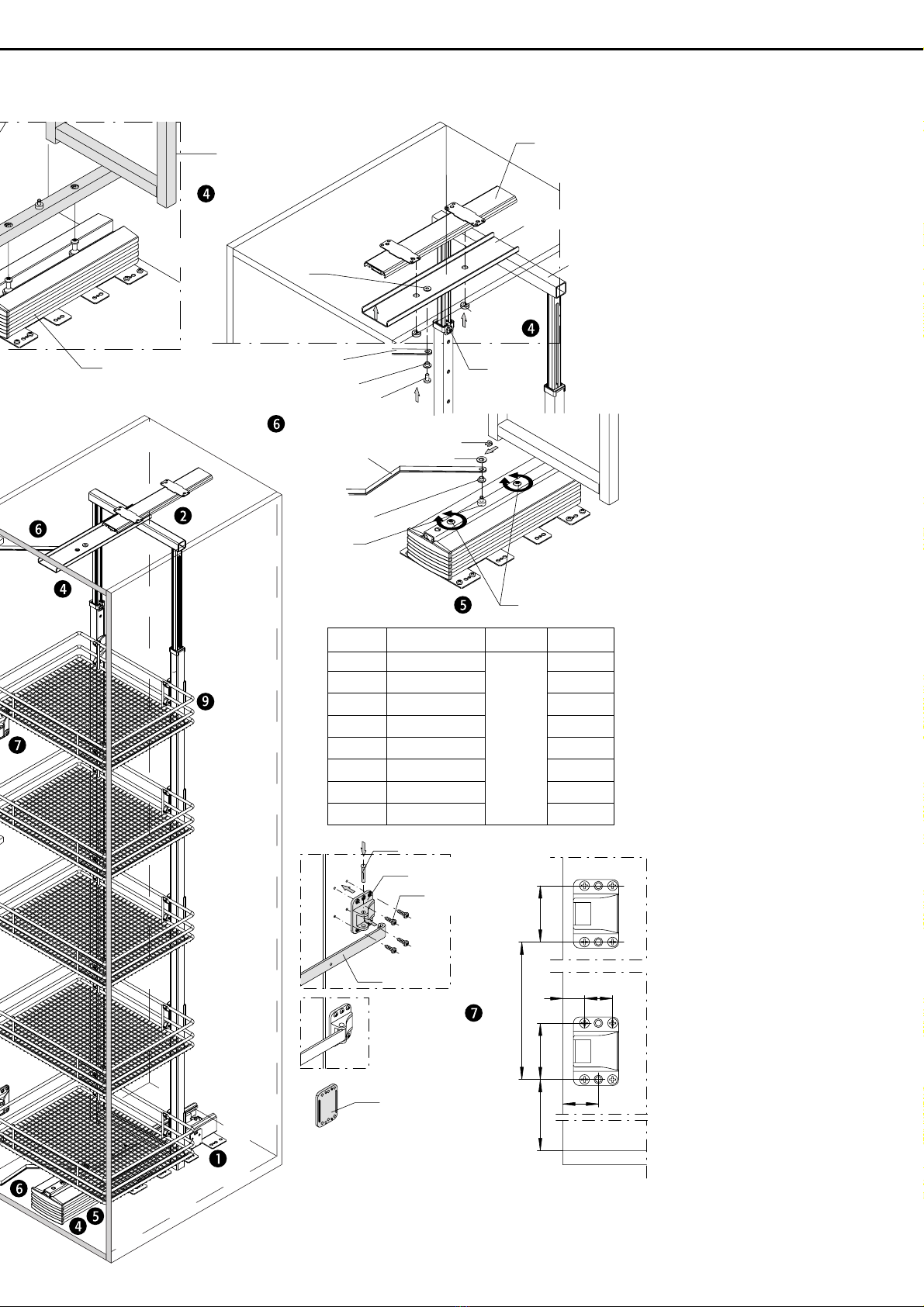
5Align sliding frame
With the aid of the two adjusting
screws ( ottom) the frame can e
aligned vertically: front adjusting
screw anticlockwise - frame is
raised at the front and tilts to the
rear, rear screw anticlockwise -
frame is raised at the rear and
tilts to the front, y turning the
screws clockwise the frame
ehaves in the opposite manner.
With the aid of these adjusting
screws the frame can also e
raised or lowered if necessary y
adjusting oth screws y the
same amount.
6Connect frame to front
Pull out the frame, screw the top
coupling arm together with the
flange sleeve and the M 6 x 12
screw to the threaded sleeve on
the top cover plate. Fit the ottom
coupling arm together with the
flange sleeve and a spacer to the
pin and secure with the washer
and locking clip.
Fastening material:
Screw M6 x 12
Flange sleeve 2 off
Washer
Locking clip
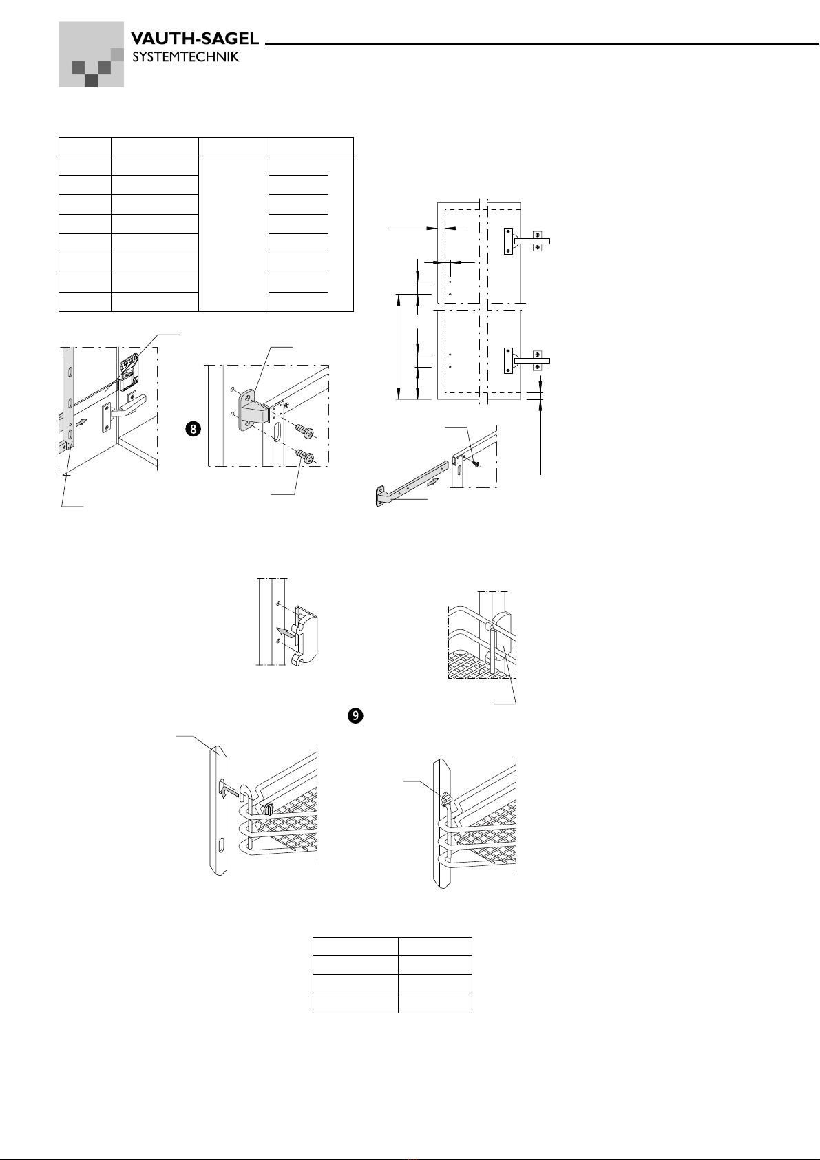
7Fit plastic brac ets
The ottom plastic racket is to
e fitted such that the distance
etween the ottom shelf and the
ottom fastening holes is the
same as dimension "A" as per
ta le A. The position of the top
plastic racket is dependent on
the installation height. The
distance "B" is to e found in
ta le A.
If there are fouls with existing
front hinges, then the dimension
"A" will need to e adjusted as
appropriate - Caution: this
situation must also e taken into
account in point 8 "Fit front
frame"!
Now place the rails in the plastic
rackets and connect with
earing pins
Fastening material for fitting
without spacer
(not included):
Pan head screws 4.0 x 16
or Euro screws 6.3 x 13
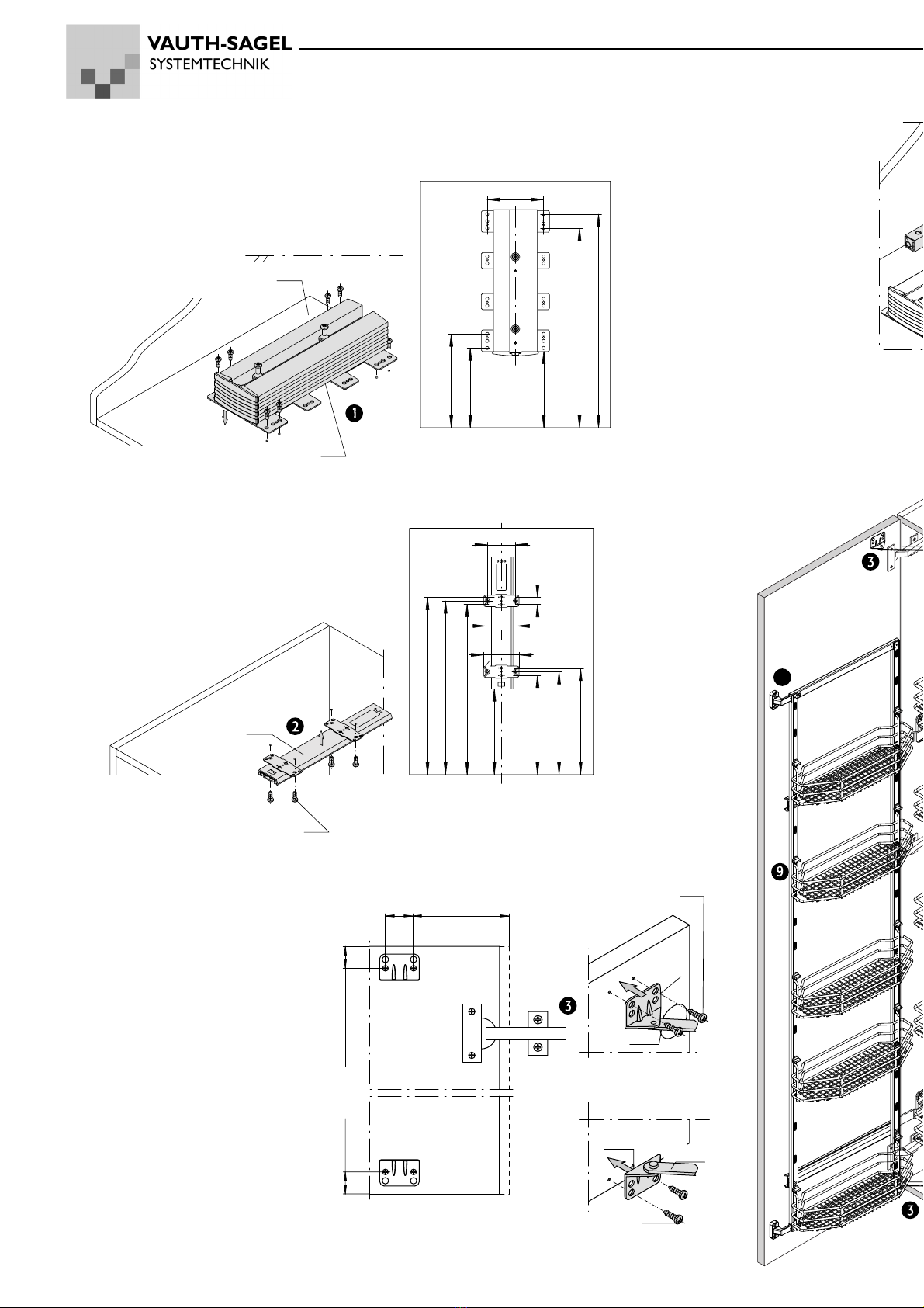
Sliding frame
Guide unit
Ball earing guide
Top
Plastic
clip
Cover plate
Clamping
screw
Threaded
sleeve
Flange sleeve
M6 x 12
Top coupling arm
Flange sleeve
Bottom coupling arm Washer
Adjusting screws
Bearing pin
Plastic racket
Pan head screws
4.0 x 16
Rail
5 mm spacer
availa le as an
optional extra
Pin
Table A
Installation Dimension Dimension
heights "A" "B"
DUSA 1 650 - 950 190
DUSA 2 950 - 1200 510
DUSA 3 1200 - 1450 718
DUSA 4 1450 - 1700 162 718
DUSA 5 1700 - 1950 1118
DUSA 6 1900 - 2150 1118
DUSA 7 2150 - 2350 1118
If may e necessary, depending on the
design of the hinges, to fit spacers to
increase the distance etween the rail
and side of the ca inet. These are
availa le as an optional extra.
Sliding section