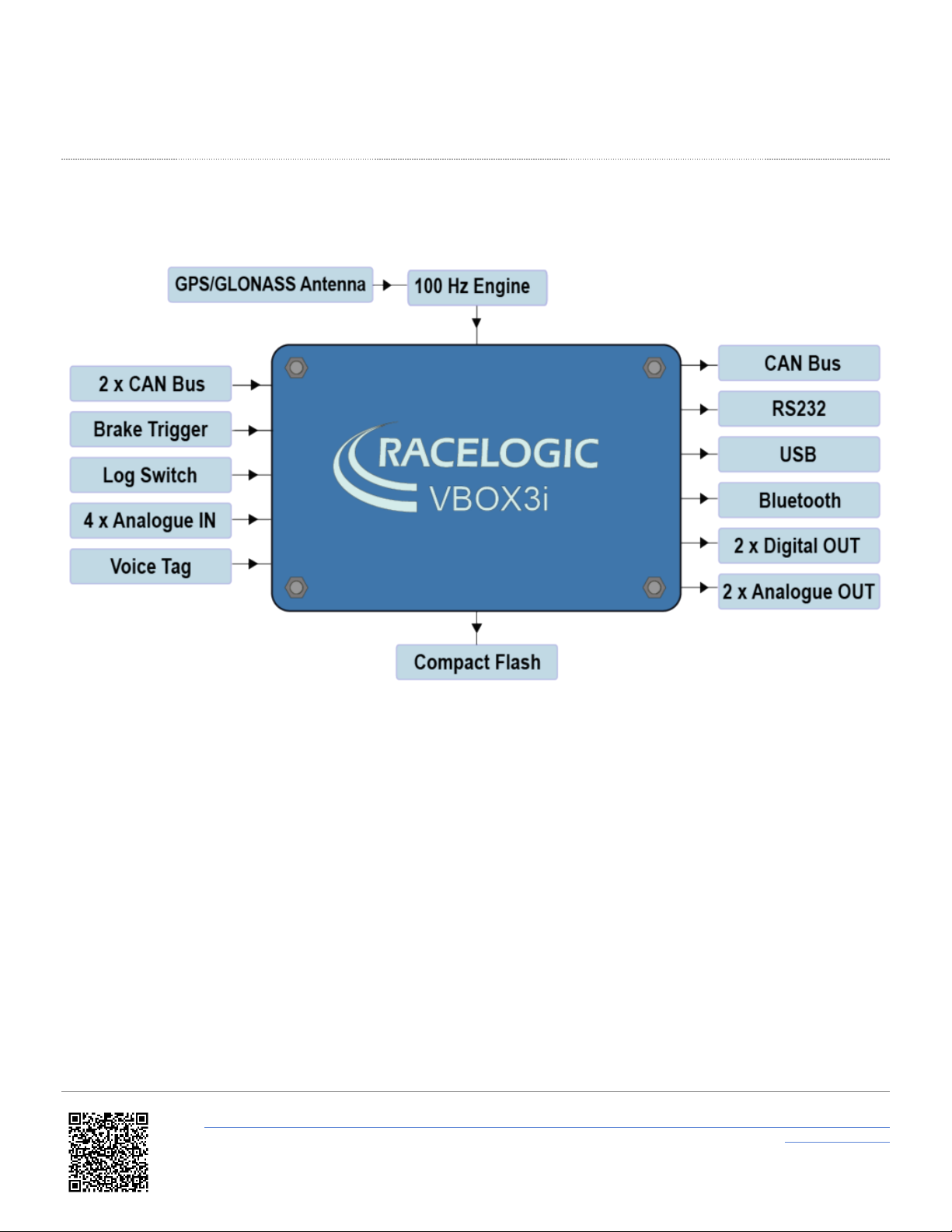
VBOX 3i User manual

Automotive VBOX 3i User Guide
•01 - VB3i Introduction
•02 - VB3i GNSS Antenna Placement
•03 - VB3i Front Panel
•04 - VB3i LE Indicators
•05 - VB3i Logging
•06 - VB3i ual Antenna Setup
•07 - VB3i VBOX Setup Overview
•08 - VB3i CAN
•09 - VB3i Analogue and igital I/O
•10 - VB3i ynamic Modes
•11 - VB3i GPS / RTK
•12-1 - VB3i IMU Integration - In-Vehicle Mounted
•How to Mount the IMU
•Kalman Filter Calibration
•VB3i V3-V5 Additional IMU04 Channels
•12-2 - VB3i IMU Integration - Roof Mounted
•13 - VB3i Bluetooth Pairing
•14 - VB3i Voice Tagging
•VB3i Analogue Input PIN OUTS
•VB3i Cable Identification
•VB3i CAN Output
•VB3i EC eclaration of Conformity
•VB3i PIN OUTS
•VB3i Technical Specification
1

01 - VB3i Introduction
Configuration
VBOX 3i can be configured using VBOX Manager via a RLCAB005 cable, or can be connected to a computer and
configured using VBOX Setup software. You can connect to a computer via Bluetooth, a RLCAB001 cable to
the 'SER' input and the computer's serial port (USB-serial adapter may be required), or via a RLCAB066-2 cable to one
of the computer's USB ports.
For A AS applications, connection between the VB3i and computer should be made via USB or Bluetooth to ensure
optimum performance.
Power Supply
Included with the VBOX 3i is a cigar lighter power cable, which is the primary source of power input. This is terminated
in a 2-way connector and mates with the 2-way ‘PWR’ socket on the VBOX 3i.
The VBOX 3i can be powered from a wide range of voltage sources. When considering batteries as a power source,
please note that the minimum operating voltage of the VBOX 3i is 7 V. The maximum operating voltage input must not
exceed 30 V C. Failure to observe this could result in damage to the VBOX.
Note - Using an External Power Backup prevents the system shutting down under temporary power loss.
Warning
The VBOX can be connected to other Racelogic input modules including the A C03, A C02, TC8, FIM02/3 and
multifunction display. Please note that the voltage supply to Racelogic modules connected to the VBOX will be at the
same level as the VBOX power input. Therefore, when using any of the Racelogic peripherals with VBOX 3i, the
input voltage must not exceed 15 V. Failure to observe this could result in damage to the module and possibly the
VBOX 3i.
When running the VBOX from a battery pack, the VBOX will sound a warning tone to indicate when the battery voltage
https://en.racelogic.support//Product_Info/VBOX_ ata_Loggers/VBOX_3i_Range/VBOX_3i_User_Guide_(All_Variants)/01_-
_VB3i_Introduction
2

is reaching the minimum operating voltage level. When this tone is heard, the battery pack requires re-charging or
replacing.
The VBOX 3i has been designed to generate as little heat as possible, and it has a wide operating temperature range.
However, it is good practice to mount the VBOX 3i in a position where it has sufficient airflow around the case.
You must connect the GNSS antenna before connecting power to the VBOX 3i. This is necessary because on power-up
the VBOX 3i will look for a connected GNSS antenna and automatically adjust its gain for optimum performance.
RACELOGIC external modules operate from a 12 V vehicle supply. Therefore, when using external modules, VBOX
supply must not exceed 15 V C.
Hardware Variants
VBOX 3i is available in three variants:
•VB3i: A single antenna version, offering position accuracy of up to 50 cm.
•VB3iD (formerly VB3iSL): A dual antenna version including the same features as VB3i but with the addition of a
second GNSS Antenna, meaning it can also measure slip angle, pitch/roll angle and heading at 100 Hz.
•VB3iDR (formerly VB3iSLR): A dual antenna version with RTK, offering centimetre level position accuracy and
multi-vehicle/ multi-target A AS testing.
Along with an extra antenna socket for dual antenna systems, variants can also be identified using the product
label sticker on the side of the unit.
VB3i label VB3iD label
https://en.racelogic.support//Product_Info/VBOX_ ata_Loggers/VBOX_3i_Range/VBOX_3i_User_Guide_(All_Variants)/01_-
_VB3i_Introduction
3

VB3iDR label
Inputs/Outputs
VBOX 3i (VB3i)
https://en.racelogic.support//Product_Info/VBOX_ ata_Loggers/VBOX_3i_Range/VBOX_3i_User_Guide_(All_Variants)/01_-
_VB3i_Introduction
4

VBOX 3i Dual Antenna (VB3iD)
VBOX 3i RTK (VB3iDR)
https://en.racelogic.support//Product_Info/VBOX_ ata_Loggers/VBOX_3i_Range/VBOX_3i_User_Guide_(All_Variants)/01_-
_VB3i_Introduction
5

Inputs
•100 Hz GPS / GLONASS Engine
VBOX 3i features a powerful GNSS engine capable of providing 100 Hz signal update rate for all GPS/GLONASS
parameters (i.e. velocity, heading and position). Velocity and heading are calculated via oppler Shift in the GNSS
carrier signal, providing you with unparalleled data accuracy.
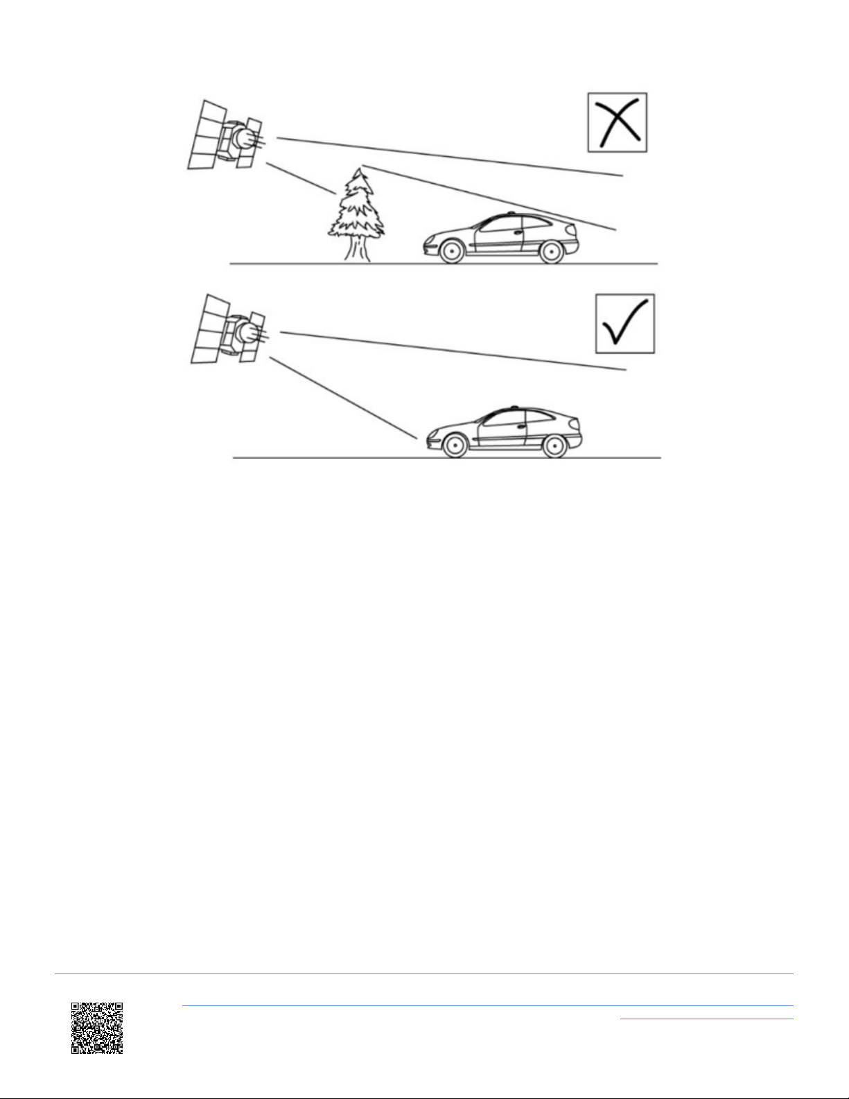
•GPS/GLONASS Antenna(s)
All standard parameters like time, speed, distance, and position are measured at the primary antenna. The
secondary antenna (dual antenna systems and VBOX 3i V4G only) enables logging of additional channels like slip
angle, pitch or roll angle (depending on antenna orientation).
•Base Station Radio Link (RTK systems only)
Can be used in conjunction with an RTK differential Base Station to obtain centimetre-level positional accuracy.
•2x CAN Bus
Two CAN Bus interfaces are available; a Racelogic CAN bus and a customer VCI bus. The Racelogic CAN bus is
designed to interface with Racelogic external modules, such as TC8, FIM03 and IMU04. The customer VCI bus is
designed to connect third party CAN devices, to log additional VCI CAN data to the VBOX (i.e. vehicle CAN bus,
Steering wheel sensor). Having separate CAN bus connections allows the user to connect to separate CAN data
sources without risk of re-broadcast on to customer VCI source. 64 external CAN channels can be logged by the
VBOX, of which up to 32 CAN channels can be logged from Racelogic modules, up to 16 CAN signals can be
logged on the VCI customer bus and up to 64 CAN channels can be logged from other channels. When logging
data from another source, VBOX Setup software can be used to load signal data from an industry standard CAN
database file (. BC).
•Brake Trigger
By using a physical pressure switch on the brake pedal, a precise 'start of braking event' can be captured. The
brake/event trigger input is oversampled to 25 ns for high distance accuracy.
•Log Switch
A start/stop logging switch allows users to manually choose when they wish to record data.
•4x Analogue Inputs
Each of the four analogue input channels has a dedicated analogue converter. ata is recorded from each channel
simultaneously to avoid latency between analogue channel data. The name, scale and offset of each analogue
input channel can be adjusted using VBOX Setup software to allow sensor calibration and therefore logging of data
in standard SI units. The analogue input connector also provides two power outputs that may be used for driving
sensors. These are in the form of a 5 V C supply and an output equal to the VBOX power supply voltage. If the
VBOX is set to 100 Hz log rate, then the additional option of 500 Hz analogue data sampling will be present and
available.
•Voice Tagging
VBOX 3i can record a GNSS synchronised WAV audio tag of up to 30 seconds long, captured to a time accuracy of
0.5 sec. The recorded WAV file is then logged to the CF card.
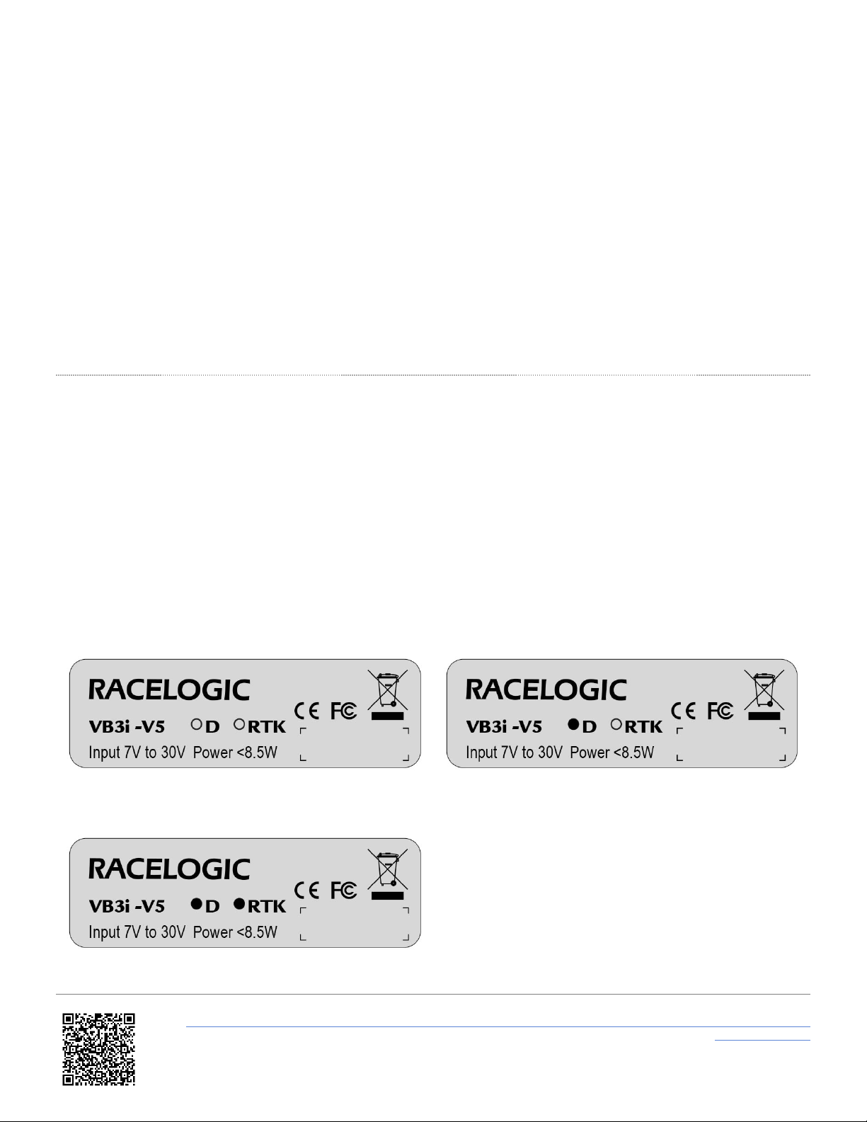
•Power Supply
VBOX 3i can accept a supply voltage between 7 – 30 V C. Low current consumption results in extended battery
life.
https://en.racelogic.support//Product_Info/VBOX_ ata_Loggers/VBOX_3i_Range/VBOX_3i_User_Guide_(All_Variants)/01_-
_VB3i_Introduction
6

Outputs
•CAN Bus
The VCI customer CAN bus can be utilised to output standard VBOX data parameters, plus up to 12 additional data
channels from connected external source or internal modules (i.e. A AS, dual antenna).
The baud rate and CAN I 's for these outputs are user configurable.
•RS232
The RS232 connector is used for VBOX configuration and output of real-time GNSS data. Provides the facility to
connect to a radio telemetry system to offer PC monitoring of test data.
•USB
VBOX 3i USB connector can be used for VBOX configuration and to output real-time data at 100 Hz to a PC.
•Bluetooth
VBOX 3i comes equipped with an internal Bluetooth Radio, allowing remote configuration and remote output of real-
time GNSS data to any Bluetooth capable PC or ata logger. The Bluetooth connection is capable of sending data
at the full 100 Hz rate.
•2x Digital Outputs
The first digital output is assigned to 'Speed/ istance' with adjustable 'Pulses per Meter' setting, while the second
output is a level switch output enabling users to select any one of the logged channels and assign it a threshold
value, e.g. output high (5 V) when speed greater than 20 kmh.
•2x Analogue Outputs
Both 16 bit analogue outputs can be configured to output any data channel being logged by the VBOX for use by
additional data logging equipment. The voltage output range is from 0 to 5 V C, with a resolution of 76 μV per bit.
•CF Card
ata is logged in a space-delimited text format. Recording time dependent on flash card capacity, log frequency,
number of channels and logging conditions. Approximately 29 MB per hour used when logging GNSS data at 100
Hz; approx. 182 MB per hour total logging capacity.
Note: Large VBO files may cause issues when loading into VBOX Test Suite, depending on PC specification. The
higher the set recording frequency, the larger the logged data file will be.
Technical specifications vary for each VBOX 3i version. Please see the datasheets for detailed information.
https://en.racelogic.support//Product_Info/VBOX_ ata_Loggers/VBOX_3i_Range/VBOX_3i_User_Guide_(All_Variants)/01_-
_VB3i_Introduction
7

02 - VB3i GNSS Antenna Placement
Single Antenna Systems
The GNSS antenna supplied with the VBOX is a 5 V active antenna. For the best possible signal quality, it is important
to maintain a clean connection between the antenna and the VBOX. Before fixing the antenna to the VBOX, ensure that
there are no dust particles in either connector. Replacement antennae are available by contacting your VBOX
distributor.
The antenna is a magnetic mounting type for quick and simple mounting to the vehicle roof. For optimum GNSS signal
reception, make sure that the antenna is fitted to the highest point of the vehicle away from any obstructions that may
block satellite reception. The GNSS antenna works best with a metal ground plane underneath (a metallic vehicle roof is
perfect for this)
Please also note that when using any GNSS equipment, a clear sky view is important. Objects in the surrounding area
such as tall buildings or trees can block the GNSS signal causing a reduction in the number of satellites being tracked,
or introducing reflected signals that can decrease the accuracy of the system. Note that clouds and other atmospheric
conditions do not affect the VBOX’s performance.
https://en.racelogic.support//Product_Info/VBOX_ ata_Loggers/VBOX_3i_Range/VBOX_3i_User_Guide_(All_Variants)/02_-
_VB3i_GNSS_Antenna_Placement
8

GNSS antennas require a ground plane to operate correctly. This helps to reduce unwanted reflections of the GNSS
signal caused by nearby objects, and usually the metal roof of a vehicle performs this function. However, if a test
requires an antenna to be placed either off the vehicle, or on a vehicle that does not have a metallic roof, a special
ground plane antenna must be used. This has an internal ground plane and can operate perfectly without the need for
mounting on a metal surface. Ground plane antennas are available from your VBOX distributor.
https://en.racelogic.support//Product_Info/VBOX_ ata_Loggers/VBOX_3i_Range/VBOX_3i_User_Guide_(All_Variants)/02_-
_VB3i_GNSS_Antenna_Placement
9

ual Antenna Systems
For further info on slip/pitch and slip/roll setups, click here.
When testing using dual antenna mode, the greater the antenna separation, the greater the accuracy of the dual
antenna derived data channels.
Slip Angle Accuracy Pitch/Roll Angle Accuracy
<0.2° rms at 0.5 m antenna separation
<0.1° rms at 1.0 m antenna separation
<0.067° rms at 1.5 m antenna separation
<0.05° rms at 2.0 m antenna separation
<0.04° rms at 2.5 m antenna separation
<0.14° rms at 0.5 m antenna separation
<0.07° rms at 1.0 m antenna separation
<0.047° rms at 1.5 m antenna separation
<0.035° rms at 2.0 m antenna separation
<0.028° rms at 2.5 m antenna separation
Media, iframe, embed and object tags are not supported inside of a P F.
https://en.racelogic.support//Product_Info/VBOX_ ata_Loggers/VBOX_3i_Range/VBOX_3i_User_Guide_(All_Variants)/02_-
_VB3i_GNSS_Antenna_Placement
10

Some vehicle roofs limit the potential separation value. In this case a roof mount (RLACS171) can be utilised to
increase separation.
Antennas should be positioned so that the gold antenna connector of primary and secondary antennas (A+B)
are pointing in the same direction. This matching positioning ensures that the separation measurement is relative.
We recommend you measure separation from outer edge of antenna connector A, to same outer edge of antenna
connector B. Note that accurate entry of antenna separation is essential for dual antenna operation.
https://en.racelogic.support//Product_Info/VBOX_ ata_Loggers/VBOX_3i_Range/VBOX_3i_User_Guide_(All_Variants)/02_-
_VB3i_GNSS_Antenna_Placement
11

• In pitch alignment, the primary antenna (ANT A) should be placed towards the rear of the vehicle, and the reference
antenna (ANT B) placed at the front.
• When in roll alignment, the primary antenna (ANT A) should be placed to the left of the vehicle, and the reference
antenna (ANT B) placed to the right.
When mounting the antennas directly to the vehicle roof, ensure that the antenna placement still follows the guidance of
the single antenna above (i.e. clear ground-plane, away from obstruction).
Where possible, antennas should be placed on a level plane. The measured distance between the antennas should be
the 2 distance between the antennas as viewed from above. It is not the straight-line distance between the antennas,
regardless of the mounting angle.
https://en.racelogic.support//Product_Info/VBOX_ ata_Loggers/VBOX_3i_Range/VBOX_3i_User_Guide_(All_Variants)/02_-
_VB3i_GNSS_Antenna_Placement
12

Both antenna cables must be the same length!
Timing is a very important aspect of the dual antenna lock and identical cable lengths will ensure that signal
propagation delays do not cause unreliable dual lock.
Satellite Elevation Mask
This feature can be used to improve GNSS signal quality when nearby obstacles like trees and building are reflecting or
temporarily obscuring the signal from satellites at low elevation. Raising the mask will cause the GNSS engine to ignore
satellites below the mask angle, so must be used carefully as it also reduces the total number of received satellites.
The elevation mask angle can be changed in VBOX Setup and by using VBOX Manager.
GNSS Coldstart
A GNSS coldstart may be required when:
• The GNSS engine has locked up.
• VBOX is struggling to acquire satellite lock.
A GNSS coldstart forces the GNSS engine to reset its downloaded almanac of current satellite positions. This can be
useful if the VBOX 3i is having trouble locking onto satellites, which typically occurs if the VBOX 3i has not been used for
several weeks or if it was last used a long distance (over one thousand miles) away from the current location.
https://en.racelogic.support//Product_Info/VBOX_ ata_Loggers/VBOX_3i_Range/VBOX_3i_User_Guide_(All_Variants)/02_-
_VB3i_GNSS_Antenna_Placement
13

After performing a GNSS coldstart leave the VBOX 3i powered up in a static location where the antenna has an
unobstructed view of the sky until the ‘SATS’LED becomes solid green.
Once the VBOX3i has downloaded the new almanac it will reacquire satellites in noisy situations (such as near trees,
buildings and under bridges) much quicker. It will also acquire satellite much quicker on power-up.
To perform a GNSS coldstart on the VBOX3i perform the following actions:
1. Press and hold the ‘LOG’button on the front of the VBOX 3i for five seconds until a long beep is sounded.
2. When the button is released the ‘SATS’LED will start to flash red showing that the coldstart has been performed
and the GNSS engine is now not locked onto any satellites.
3. After approximately 30 – 45 seconds, the ‘SATS’LED will start to flash green /orange indicating that satellite lock
has been achieved and indicating the number of satellites that it is locked onto.
Important notes
When a GNSS coldstart is carried out, please note that this resets the GPS and RTK mode to 'None'. Also, if using a
dual antenna system, the VBOX 3i /3i R will reset dual antenna separation to default settings (1 m).
https://en.racelogic.support//Product_Info/VBOX_ ata_Loggers/VBOX_3i_Range/VBOX_3i_User_Guide_(All_Variants)/02_-
_VB3i_GNSS_Antenna_Placement
14

03 - VB3i Front Panel
Buttons
VBOX 3i has two membrane buttons on the front panel, LOG and FUNC. LOG is used to start and stop logging to the
compact flash card, and FUNC is used to switch between two sample rates, 100 Hz and 20 Hz.
LOG
The LOG button will override any of the automatic logging thresholds set in the VBOX. For example, if you have set the
VBOX to log all the time, the LOG button will toggle logging on and off. If you have set the VBOX to ’log only when
moving’ and you are moving, pressing the LOG button will stop the VBOX logging and close the file on the compact
flash. Logging will now not continue even if you are moving until the LOG button is pressed again or the compact flash
card is removed and reinserted. The VBOX will then continue to log only when moving. Note that if the VBOX is using
‘log only when moving’ log mode, and the vehicle has been stationary from power-up, the LOG button will not initiate
logging. If you want the VBOX to log, you would have to use VBOX Manager or VBOX Setup to change the log mode to
‘Log Continuous’.
- Every time the logging is toggled with the LOG button, a new file is created.
- When the VBOX is logging, the the green LOG LE will be solid and the blue CF light will flash.
https://en.racelogic.support//Product_Info/VBOX_ ata_Loggers/VBOX_3i_Range/VBOX_3i_User_Guide_(All_Variants)/03_-
_VB3i_Front_Panel
15

Important - Do not remove the CF card or power down whilst the CF LED is flashing. If you need to remove the
card or power down whilst the CF LED is flashing, then press the LOG button first to stop the VBOX logging.
Failure to do so will result in data loss or corruption.
FUNC
Pressing the FUNC button briefly flashes the LE ’s and beeps to indicate the current sample rate. A slow flash (once
per second) on all the LE ’s indicates 20 Hz, and rapid flashing (5 times a second) indicates a 100 Hz sample rate. A
running sequence of lights indicates a sample rate other than 100 Hz or 20 Hz. Pressing and holding the FUNC button
for 5 seconds toggles the current sample rate. The sample rate can also be set using VBOX Manager or VBOX Setup.
Default setup
The default factory settings are restored to the VBOX by pressing and holding the FUNC and LOG buttons for 5
seconds. This will put the VBOX 3i into the default factory settings; 100 Hz log rate, log continuous mode, Fixed 20 ms
CAN delay, Output CAN Tx Identifiers on, Racelogic CAN on the CAN port, customer VCI CAN on the SER port, and
only standard GPS channels and brake trigger event time set to log.
VB3i RS232 / CAN Ports
Click here for information on the VB3i RS232 protocol.
VBOX 3i is equipped with 2 CAN Bus interfaces and 2 RS232 serial ports. The primary RS232 port is used for all
communication between the VBOX and laptop PC. The primary port is marked SER on the VBOX 3i front panel. The
primary RS232 port (SER) is able to transmit live data from the VBOX to the PC for viewing and performing real-time
tests. It is important to note however that due to limitations of the PC serial port, live data transfer of all channels is
limited to 20 Hz, at 50 Hz only standard GPS channels and Solution Type should be transmitted, and at 100Hz only
Sats, Time, Speed, and Trigger Event Time should be transmitted. Logging too many channels at too high a rate is likely
to cause drop-outs and loss of data.
Therefore for maximum accuracy, tests performed at a GPS sample rate above 20 Hz should be logged to compact
flash and post processed.
Note that when the VBOX is set to an A AS mode, RS232 serial transmit from the SER port will be disabled.
The secondary RS232 port is used for connection to a Telemetry Radio module allowing the reception of ifferential
GPS ( GPS) data for local correction from a Racelogic Local GPS basestation, or Moving Base solution. The
secondary RS232 port is located in the connector marked CAN on the VBOX 3i front panel.
https://en.racelogic.support//Product_Info/VBOX_ ata_Loggers/VBOX_3i_Range/VBOX_3i_User_Guide_(All_Variants)/03_-
_VB3i_Front_Panel
16

The CAN Bus ports A and B are located in the VBOX 3i connectors “CAN” and “SER” respectively. The function of these
ports is configurable by the user using VBOX Setup to toggle the Racelogic Bus profile. The Racelogic CAN bus is used
for connected Racelogic modules or displays. The Vehicle CAN bus (VCI) is for use by third party CAN equipment,
whether logging to the VBOX, or logging from the VBOX. For dual use of RS232 and CAN from one of the sockets you
will require a 5 way Lemo splitter RLVBACS024.
Power supplied to external Racelogic CAN modules through the “CAN” or “SER” cables is at the same voltage
as the input power supply. Therefore when using Racelogic external CAN modules (eg; MFD or ADC03), the
VBOX 3i supply voltage must not exceed 15 V DC.
https://en.racelogic.support//Product_Info/VBOX_ ata_Loggers/VBOX_3i_Range/VBOX_3i_User_Guide_(All_Variants)/03_-
_VB3i_Front_Panel
17

USB
The VBOX includes a USB 2.0 connection that can be used for VBOX configuration and the output of real-time serial
data at the full 100 Hz data rate.
Before you connect your VBOX to your PC ensure that you have downloaded and installed VBOX Setup software, as
this will also put the required USB drivers onto your PC.
The software installation will place the VBOX USB drivers in the following location on your computer. C:\program files\
Racelogic\ rivers.
VB3i drivers can also be downloaded from the rivers and Utilities section of vboxautomotive.co.uk. You can find more
information about how to install the drivers here.
When you connect a powered up VBOX 3i to your PC with the supplied USB lead, your PC will recognise the presence
of new hardware and open the typical Windows install window for new hardware. Follow the on screen prompts and
point the Windows installation to the location of your drivers.
https://en.racelogic.support//Product_Info/VBOX_ ata_Loggers/VBOX_3i_Range/VBOX_3i_User_Guide_(All_Variants)/03_-
_VB3i_Front_Panel
18

04 - VB3i LE Indicators
SATS
• Flashing red indicates no satellites in view
• Flashing green sequence indicates the number of GPS satellites currently being tracked. Each flash indicates a
satellite with a short pause between each sequence.
• Flashing orange sequence indicates the number of GLONASS Satellites currently being tracked. Each flash
indicates a satellite with a short pause between each sequence.
Sequence showing 1 Satellite
Sequence showing 4 Satellites
Sequence showing 0 Satellites
https://en.racelogic.support//Product_Info/VBOX_ ata_Loggers/VBOX_3i_Range/VBOX_3i_User_Guide_(All_Variants)/04_-
_VB3i_LE _Indicators
19

Note for VB3i V1 units
When the filter is enabled and the IMU is connected, the satellite LE will remain off to act as an indicator for the IMU
integration status. Only when the filter is initialised and movement is detected will the SAT LE return to its normal
operation.
The user will need to leave 1 minute after powering the VBOX on with the IMU connected before starting to move. This
occurs on every power up of the VBOX unit.
IFF/ GPS
• Off indicates that no GPS mode is set or is in MB-Base mode.
• Flashing orange indicates GPS is set but not locked (either 2 cm RTK, 40 cm local GPS, MB-Rover or NTRIP).
• Solid orange indicates a 'Float' RTK status (either 2 cm RTK, MB-Rover or NTRIP) or ‘Fixed’ GPS lock (40 cm
local GPS or SBAS).
• Solid green indicates a ‘Fixed’ RTK lock (either 2 cm RTK, MB-Rover or NTRIP).
UAL (VB3i / R units only)
• Solid orange indicates that dual antenna mode is enabled.
• Solid green indicates dual antenna lock is fixed.
PWR
• Solid green indicates that a suitable power source is connected, unit is fully booted and ready to use.
• Solid red indicates that the VBOX is not ready to operate either because it is still booting up, settings are being
written to the unit or because there is an error condition.
IN
• Solid green indicates that the brake trigger input has been activated/triggered.
CAN
• Flashing green indicates that expected incoming CAN data has been decoded properly and is being logged.
• There is no illumination to indicate that there is incoming Serial traffic through this socket.
https://en.racelogic.support//Product_Info/VBOX_ ata_Loggers/VBOX_3i_Range/VBOX_3i_User_Guide_(All_Variants)/04_-
_VB3i_LE _Indicators
20
Table of contents
Popular Automobile Accessories manuals by other brands

Axxess
Axxess AXGMLN-09 installation instructions

Thule
Thule Rapid System Kit 1850 instructions

ECS Tuning
ECS Tuning Ziza ES2580244 Installation procedures

Yakima
Yakima Swing Daddy 4 instructions

Mini
Mini Full Preparation Package Mobile phone owner's manual

rough country
rough country Slim Line LED Light Grille Kit manual