VC Videocomponents 13145 Technical document

MO_14511-K
Installations- und Betriebsanleitung
GERMANY
R
C
ÄnderungeninTechnik,DesignundAusstattungvorbehalten
VC-videocomponents.... aligned for professional videosystems
Dear Customer!
By selecting this VC product you have chosen a professional
device, which guarantees highest possible quality and
reliability.
Please read the following instructions carefully before
comissioning the product in order to be able to take full
advantage of all quality features regarding this product line.
GERMANY
R
CMounting and Operating Manual
Digital Video Recorder
©All contents of this document may change without prior notice
MO_13145/17.02.2010
Art. no. 13145
Art. no. 13146
Art. no. 13147


Index
Introduction to Digital Video Recorder------------------2
Front panel buttons ------------------3
Rear panel buttons -----------------------------------------4
DVR installation:video output connection-------------5
DVR installation:video input connection---------------5
DVR installation:sensor installation---------------------6
DVR installation:alarm installation-----------------------7
Power up the unit -------------------------------------------8
On-screen display-------------------------------------------9
Operation guide:Main menu------------------------------10
Operation guide:Camera select--------------------------10
Operation guide:Record select---------------------------11
Operation guide:Record mode---------------------------11
Operation guide:Record framerate----------------------12
Operation guide:Video quality----------------------------13
Operation guide:Record schedule-----------------------14
Operation guide:Sub menu-password change--------15
Operation guide:Sub menu-time set---------------------16
Operation guide:Sub menu-display format-------------16
Operation guide:Sub menu-Link to PC------------------16
Operation guide:HDD setup -------------------------------17
Operation guide:Sensor setup ----------------------------18
Operation guide:Playback ---------------------------------19
Appendix I Regulatory --------------------------------------20
Appendix II PC viewer --------------------------------------21
Appendix III HDD installation -----------------------------23


Introduction to Digital Video Recorder (DVR)
The digital video recorder (DVR) is for recording/retrieving video streams
from up to 4 channels at the same time. It adopts a digital image
compression technology to compress the input channel video streams,
and uses HDD to record the compressed video stream.
The following operation guide explains how to operate/manage the DVR,
and the following installation guide explains how to install DVR at your
home or HDD into the DVR.
Hope you enjoy it, use it to protect your home, and eventually make your
home as SAFE HOME.
Introduction
2

3
4
11
8
9
10
15
14
13
12
2
1
5
6
7
1. &(Menu) button: press to display Operation menu option
2. (Recording button): press to start recording.
3. (Stop recording/playback button):press stop recording/playback
(the authorized password is requested upon stopping record;
the default password is 111111)
4. (Fast forward button): press to play the recorded stream faster.
5. (Playback button): press to start playback
6. (Pause button): press to pause the video playback
7. Reverse:press to playback backward
8. Channel 1 button: press to select channel 1
9. Channel 2 button: press to select channel 2
10. Channel 3 button: press to select channel 3
11. Channel 4 button: press to select channel 4
12. 田All channels button: press to select all channels display
13,14. up down buttons: press to change menu field
15.(Select) button: press to change the setting value or enter into a
sub menu
Front Panel
3
3
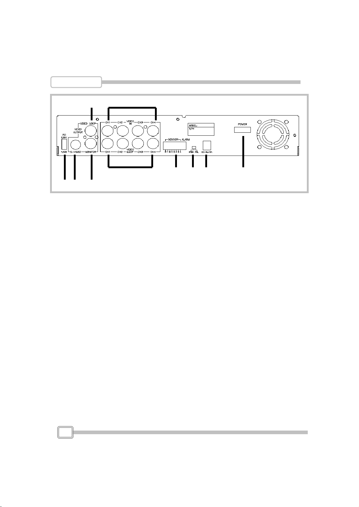
1 2 4
67 8 9 10
5
1. PC Link : USB device interface (2.0)
2. S Video
3. Video output
4. Monitor : Second Video output
5. Video loop-through
6. Video input
7. Sensor input/alarm output: 4 sensor inputs and one alarm output
8. NTSC/PAL switch
9. DC-in (12Voltage)
10. Power switch
Rear Panel
4

1.Video input connection ( TV or monitor)
Please connect TV(monitor) to the unit over the Video output connector.
The unit provides 1 x S-Video input and 2 x BNC connector.The above
Figure shows the video signal line connection.
DVR Installation
BNC connection
S-Video connection
Or through
BNC connection
S-Video connection
Or through
AC/DC adaptor
power outlet
Camera
Signal Line
Power line
5

2. Video output connection ( Camera)
Please connect Camera to the unit over the Video input connector.
The unit provides 4 x BNC connectors.The camera installation
Procedures are as following:
i. Connect the video signal line: connect the video signal line to the unit
ii.Connect camera power line: Connect camera’s adaptor to camera, and
plug in the adaptor. The complete connection with a camera will be shown
as figure below
DVR Installation
3.Sensor Installation
The unit provides 4 sensor input for 4 channels. The sensor
Installation procedures are as follows. There are two simple steps
For the installation of the sensors.
i. Connect the sensor signal line: Connect the video signal line to the unit. The
Sensor signal terminal is at the unit’s back panel
ii.Connect the sensor adaptor jack into the sensor, and plug in the adaptor.
power outlet
AC/DC adaptor
Sensor
Power line
Signal Line
CH1 CH2 CH3 CH4 Alarm out
6

DVR Installation
4. Alarm installation
The unit provides 1 internal switch for sounding alarm when the sensor is
Activated due to the unwanted entrance of anonymous visitor. The switch
Is open at normal state, but, when the alarm is activated, the switch is closed
So that the alarm gets the power. The circuitry is shown as above figure.
There are two simple steps for the installation of the alarm
i. Prepare the power supply:the alarm needs a power supply, the power supply
comes with the alarm
ii.Connect the alarm power line:the alarm power line is connected to the alarm
switch terminal.
AlarmAC/DC adaptor
power outlet
Signal Line
Power line
7
This manual suits for next models
2
Table of contents
Other VC Videocomponents DVR manuals


