vds TONDO 140 Technical document

TONDO
Rolling shutters
|
WARNING!! Before installing, thoroughly read this manual that is an integral
part of the pack
The CE mark conforms to European directive
EEC 89/336 + 92/31 + 93/68 D.L. 04/12/1992 N. 476.
Our products if installed by qualified personnel capable to evaluate risks,
comply with norms UNI EN 12453, EN 12445

2
PURPOSE OF THE MANUAL
This manual was drawn up by the manufacturer and is an integral part of the product. It contains
all the necessary information:
Ÿto draw the attention of the installers to safety related problems;
Ÿto install the device properly;
Ÿto understand how it works and its limits;
Ÿto use the device under safe conditions.
Strict observance of the instructions in this manual guarantees safe conditions as well as
efficient operation and a long life for
the product. To prevent operations that may result in accidents, read this manual and strictly
obey the instructions provided.
Instructions, drawings, photos and literature contained herein are the exclusive property of the
manufacturer and may not be
reproduced by any means.
CONTENTS
1 IMPORTANT SAFETY INSTRUCTIONS ............................................................................................................3
2 TECHNICAL CHARACTERISTICS .....................................................................................................................3
3 TECHNICAL DATA..............................................................................................................................................4
4 INSTALLATION INTRUCTIONS .........................................................................................................................4
5 ELECTRICAL WIRING SCHEME........................................................................................................................5
6 FRONT SIGHT ....................................................................................................................................................6
7 ELECTROBRAKE APPLICATION DIAGRAM.....................................................................................................6
8 BLOW UP VIEW OF THE ELECTROBRAKE .....................................................................................................7
.
9 PERIMETRAL BAND...........................................................................................................................................7

3
1 IMPORTANT SAFETY INSTRUCTIONS
ATTENTION - FOR REASONS OF PERSONAL SAFETY IT IS IMPORTANT TO OBSERVE THESE
INSTRUCTIONS.
RETAIN THESE INSTRUCTIONS
Do not let children play with fixed control devices.
Keep the remote controls out of reach of children.
Perform frequent checks on the system for any signs of unbalance and wear or damage to wires
or springs.
Do not use the equipment if it requires repair or regulation.
These warning symbols serve to remind you to pay the maximum attention when the equipment
is in use.They indicate the procedures to be followed to avoid risks to persons or things.This
gearmotor is designed to function safely if installed and used in compliance with the following
instructions. The equipment must be employed for residential uses and must be installed
indoors.
You are warned that incorrect installation can cause serious injuries.
Follow all the installation instructions.
Do not use command buttons that can simultaneously operate the equipment in both directions.
Do not command more than one gearmotor with each button.
Conduct frequent examinations on the installation to check for signs of unbalance and
wear/damage to the wiring.
Do not use the equipment if it requires repairs or adjustments.
The product cannot be installed for heights of less than 2.5. m.
The deployment of a device that guarantees omnipolar disconnection from the mains with an
opening of at least 3 mm between the contacts is obligatory.
Before installing the gearmotor for operating the rolling shutter remove all superfluous wires and
disable any equipment not necessary for motorised movement.
The control button must be placed in sight of the equipment, kept separate from the moving parts
and at a height of at least 1.5 m.
If the power cables are damaged they must be replaced by the constructor or his technical after-
sales service or, in any case, by a similarly qualified person in order to avoid all risks.
The gearmotor is designed for intermittent operation and is provided with an internal thermal
protection that interrupts power supply in the event of overheating caused by continued use.
The gearmotor automatically resets itself after a few minutes. However, regular operation will
only be possible when the gearmotor cools down.
R.P.M Capacitor
µF
Voltage
Volt
Current
A
Power
W
Thermal
min
Weight
Kg
140 10 18 230 2.5 520 4min 8
130 10 18 230 2.5 520 4min 9
180 10 22 230 3.1 700 4min 10
170 10 22 230 3.1 700 4min 11
2TECHNICAL CHARACTERISTICS
Model Torque
Nm
TONDO 140
TONDO 140+EL
TONDO 180
TONDO 180+EL

4
3 TECHNICAL DATA
·Die-cast aluminium body and rim
·Steel gears, roller bearings
·Rim mounted on bearing
·Drive shaft mounted on double ball bea rings
·Asynchronous 4 pole motor 1.400 rpm
·Class B isolation
·Thermal protection on motor: 160°C.
·Easy limit-switch adjustment
·6 mt. maximum shutter height
·Alimentation electric cable: 4x1 mm2
·Operating temperature: -20°C. ÷ 85°C.
·Fittings for electrobrake mounting.
4 INSTALLATION INTRUCTIONS
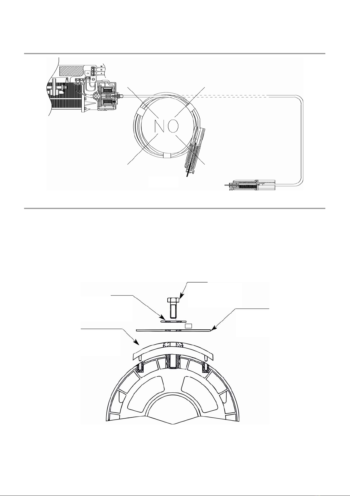
1) Drill a 10 mm diameter hole 5 cm from the centre of the shutter’s shaft (see FIG. 1);
2) Remove the M10 screws from the gear of the gearmotor.
3) Remove the two semi-gears by unscrewing the two M8 screws (using a 6 mm hexagonal wrench);
4) Carefully remove, avoiding any folding, the black plastic roller carrier band;
5) Separate the two elements of the gearmotor (upper and lower body) acting on the four M8 screws (using a 6 mm
hexagonal wrench);
6) Should the shutter shaft be less than 60 mm long, use the dedicated reducing sockets positioning them using
the previously drilled 10 mm diameter hole as a reference (point 1);
7) Join the upper and lower bodies using the four M8 screws removed before;
8) Tighten the M10 screw without hexagon nut using a 17 mm wrench and ensure it enters the shutter shaft via the
10 mm hole (previously drilled);
9) Install the roller band in its appropriate housing;
10) Apply the semi-gears, holding them with the two M8 screws;
11) Tighten the M10 screw with nut so as to block the gearmotor on the shaftand tighten said nut;
12) Place the last canvas of the shutter on the shaft and drill a 12 mm diameter hole at the same location as the
M10 threaded hole on the gear;
13) Tighten by hand the gear by 1-1½ turns by bringing the grip towards microswitch 1 (down) fig. 1 (it must turn
easily);
14) Lock the shutter to the gearmotor using the M10 screw with washer (using a 17 mm wrench);
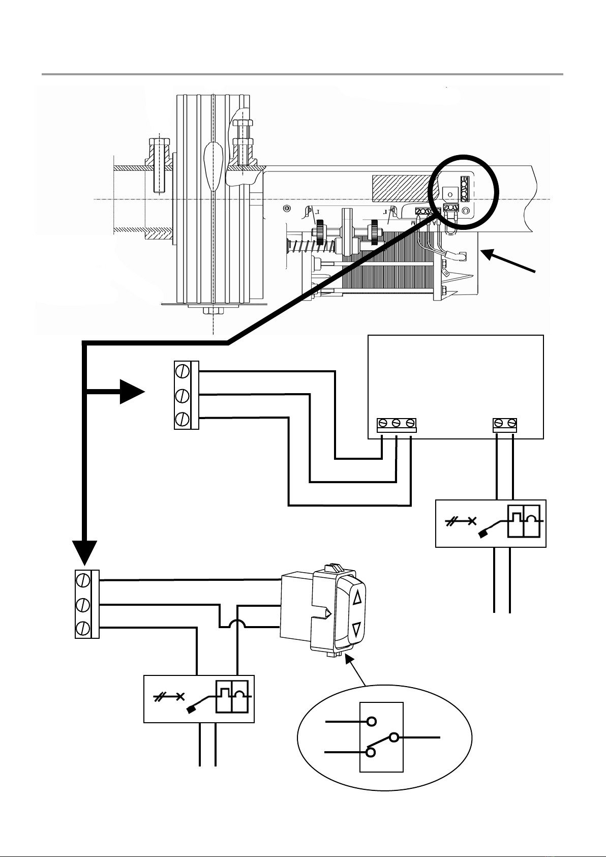
15) Make the electrical connections described in FIG. 2 passing the 4x1 mm2cable inside the shutter shaft avoiding
any contact with the rotating pars;
16) After having installed the mechanical parts and electrical contacts, proceed to regulate the end of travel;
17) Turn the end of travel grip by hand until you hear the click of the microswitch’s trigger (down regulation
completed);
18) Turn the other grip towards microswitch 2 (up). Switch on current to the gearmotor via the key selector or
button to ensure that when rising the shutter stops at the correct point to regulate the position, adjust the grip, using
solely and exclusively the electric commands taking all precautions to avoid manual lifting.
19) Should the shutter need to be installed contrary to the description in FIG. 1, the steps described above should
be carried out to the contrary as microswitch 2 will stop the descent and microswitch 1 will stop the opening.

5ELECTRICAL WIRING SCHEME
5
M
N
A
Elettronic
control panel
ENGINE
OUTPUT INPUT
230V
SECURITY
DEVICE
230V AC
50Hz
COMMON
OPENS OR CLOSES
OPENS OR CLOSES
M
N
ACOMMON
OPENS OR CLOSES
OPENS OR CLOSES
SECURITY
DEVICE
230V AC
50Hz
M
A
N
M
N
A
WITH PUSH BUTTON
BUTTON 10A-250V~
D

6
6FRONT SIGHT
7ELECTROBRAKE APPLICATION DIAGRAM
FIG. 1
ROLLER SHUTTER
SHAFT CENTRE OF
SHUTTER
M:INVERSION N:INVERSION A:COMMON
ELECTROBRAKE
BRAKELINING
MANUAL RELEASE FLEXIBLE CABLE
FIG. 2

7
8BLOW UP VIEW OF THE ELECTROBRAKE
9PERIMETRAL BAND
THE TONDO is built with a 200 mm crown wheeI, which can be converted into a 220 mm crown wheel by the use
of a perimetral band.
.
CROWN WHEE Ø 200
FIG. 3
PERIMETRAL BAND Ø 220mm
WASHER 10X40
SCREW M10x22mm
ROLLING SHUTTER CLOSURE

The data and images are for guidance only
VDS reserves the right to change at any time characteristics of the products described in
its sole discretion, without notice.
Via Circolare p.i.p. N° 10
65010 Santa Teresa di Spoltore (PE) - ITALY
Tel. +39 085 4971946 - FAX +39 085 4973849
This manual suits for next models
5
Table of contents
Popular Indoor Furnishing manuals by other brands

Habitat
Habitat Henio 807011 Assembly instructions

GWINNER
GWINNER MISANO R5516 Installation

Blumfeldt
Blumfeldt Orleans Pergola manual

fantastic furniture
fantastic furniture Arcadia Lowboy Assembly instructions

Homexperts
Homexperts MULAN EB 110 L Assembly instructions

FLEXI STORAGE
FLEXI STORAGE CLEVER CUBE 01414 Assembly instructions

FIAM.
FIAM. SW1260 Product information

Mirplay
Mirplay 732-601 Assembly instructions

Forte
Forte MADRANO MEGT031 Assembling Instruction

Notável Móveis
Notável Móveis NT 3050 Assembly instructions

Möbelix
Möbelix Panchito RecBK-2F-OTMBK Assembly instructions

Leisuregrow
Leisuregrow PRVEGG01BDL Assembly and care instructions