VEAB AW DX User manual

AW DX
Art.nr: 173124-06
SE Manual AW DX för inomhusdel till värmepump.
VI K TIGT: Läs denna manual innan produkten monteras, ansluts och tas i bruk.
Spara manualen för framtida bruk .................................................................................................................. 2
GB Manual AW DX for the indoor unit.
IMPORTANT: Please read this manual before installation, connection and putting the product into use.
Save the manual for future use. .....................................................................................................................14
DE Handbuch AW DX für Inneneinheit.
WICHTIG: Lesen Sie die Betriebsanleitung, bevor Sie das Gerät montieren, anschliessen und in
Betrieb nehmen.
Bewahren Sie die Betriebsanleitung für den zukünftigen Betrieb auf.......................................................20
FI Käyttöopas AW DX sisäyksikölle lämpöpumpulle.
TÄRKEÄÄ: Lue tämä opas ennen laitteen asennusta, liitäntää ja käyttöönottoa.
Säilytä opas myöhempää käyttöä varten. ......................................................................................................8

14
AW DX
Danger of Electric Shock.
If this warning is not observed it can lead to injury or death.
Before carrying out maintenance on the unit it is important to always turn the main switch o
and lock it in the o position.
The unit may have more than one power switch.
Reduce the risk of injury!
If this safety instruction is not observed it can lead to injury. Sheet metal edges may be sharp
or have burrs.
Use suitable protective clothing, safety glasses and protective gloves when handling, cleaning
and carrying out maintenance of this product.
AW DX
e indoor unit for heat pump is available in two sizes: AW DX22 and AW DX42
e AW DX can be used with an outdoor unit to heat and cool different premises such as warehouses, shops, and
commercial facilities. It can also be used well in dusty environments.
AW DX has the protection class IP44.
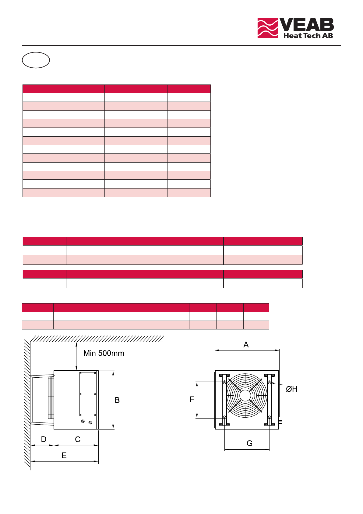
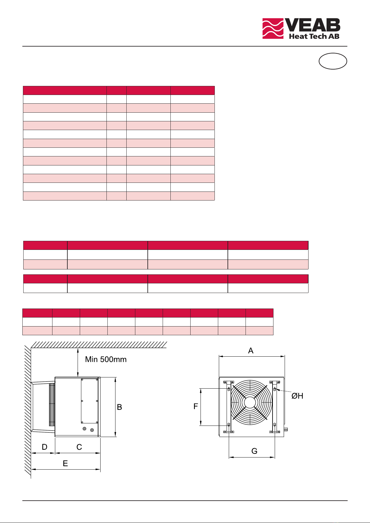
For the technical data of the indoor unit AW DX, see Appendix A.
Design
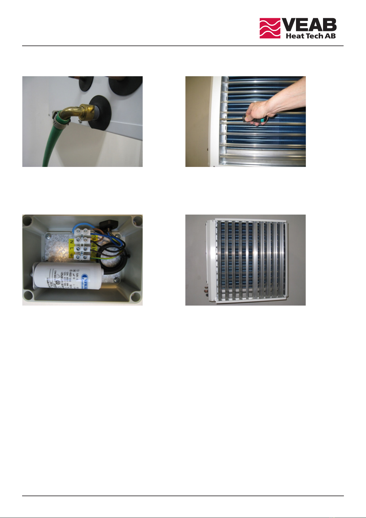
e AW DX is supplied in galvanised white painted sheet steel with cooling and heating functions.
Maintenance even in dusty places is minimised thanks to the coil element with copper pipes and aluminium fins with a 4 mm pitch.
e aluminium fins have a hydrophilic coating to ensure optimum water repellent at cooling operation.
Control
e AW DX does not have its own controller, but is controlled by the external element and its control device.
Dimensioning of external element and heat pump convector/internal element
When combining the outdoor unit with the indoor unit AW DX, it is important that the internal volume of the AW DX coil
meets the recommendations of the outdoor unit manufacturer for best and safe operation.
It is also possible to connect several indoor units to one outdoor unit.
In doing so, it is necessary to proceed in accordance with the instructions of the outdoor unit manufacturer.
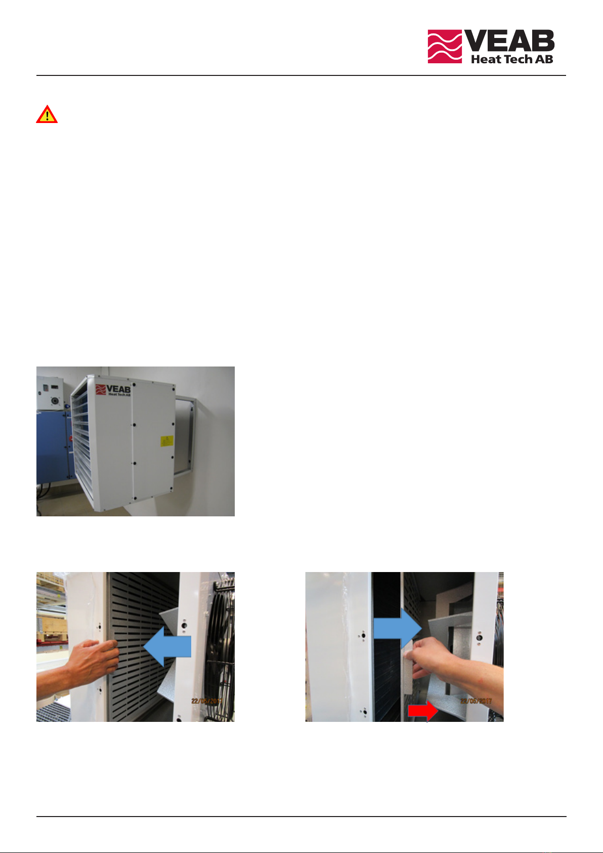
Accessories
As AW DX accessories, there are air deflectors with blades made of aluminium, which directs the air to the sides.
e name of the air deflectors is AWLH DX22/K22 resp. AWLH DX42/K42.
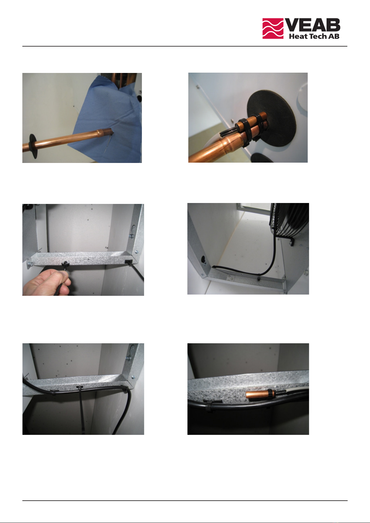
Installation
e refrigerant element must be installed by a certified refrigeration technician.
e electrical installation must be carried out by a qualified electrician.
e indoor unit must be installed at least 850 mm above the floor so that infants cannot reach the moving parts of the fan motor.
GB
Use
This appliance may be used by children aged eight years or above, people with physical and/or
mental disabilities as well as those who lack any experience – provided that they have received
detailed instructions of the appliance’s functions and any risks.
Children must not play with the appliance. Cleaning and maintenance must not be performed by
children without proper supervision.
Children under three years of age should not be near the appliance without constant supervision. Children
between three and eight years old may only turn on/shut o the appliance if it is located in a suitable posi-
tion and they have received instructions about the proper course of action, or are being supervised.
They must also be informed of possible dangers.
Children between three and eight years old may not connect the device, change its settings or
perform care/maintenance.
WARNING - Parts of this appliance can get hot and cause burns. Children and vulnerable people
must be kept under supervision.

15
AW DX
Fig. 1 Fig. 2
Fig. 3 Fig. 4
Fig. 5 Fig. 6
INSTALLING THE WALL BRACKET
1. Loosen the eight screws; see arrow markings in Fig 1.
2. Install the wall brackets with the hole facing the fan; see marking in Fig 2. is hole is for a cable tie for the cable of the fan motor.
3. When installing the indoor unit, the transport locks of the pipe connections on the left side must not be removed.
Make sure that the indoor unit is horizontal both in width and in depth; see the arrows in Fig. 3.
4. Use a 1/4” bit screwdriver to loosen the four screws securing the transport lock, see Fig. 4.
Remove the transport lock, and then reinstall the screws. Pull off the entire protective film from the white painted sheets.
CONNECTING TO THE OUTDOOR UNIT
1. e 3/8” copper pipe for the liquid connector of the coil element is marked in Fig. 5 with a yellow arrow.
AW DX42 has a 1/4” flare coupling, but this must not be used. Cut it off and solder the liquid connector.
e gas connector is a 5/8” copper pipe marked with a red arrow.
2. NOTE! e coil comes pressurised with dry air. Carefully remove the rubber plugs on the coil connection pipe, see figure 6.
Use nitrogen inside the copper tube to avoid oxidation, during soldering.

16
AW DX
Fig. 7 Fig. 8
Fig. 9 Fig. 10
Fig. 11 Fig. 12
3. Pull off the rubber seal from the connection pipe and protect the sheet against discolouration with a flame retardant, see Fig. 7.
Attention! Make sure the nitrogen can freely exit so that no overpressure occurs during soldering.
4. e sensor for the liquid pipe is installed outside the internal element frame, see Fig. 8.
Use contact paste and straps with metal locking, insulate with insulating tape.
5. Attach the supplied straps in the hole on the inside of the wall bracket where the fan motor cable is routed, see Fig. 9.
6. Fix the motor cable with the straps, see Fig. 10. en install the control box on the wall.
7. If the control equipment of the outdoor unit is equipped with a separate room sensor, it can be fixed with a smaller
cable tie on the inside of the bracket, see Figs. 11 and 12.

17
AW DX
Fig. 13 Fig. 14
Fig. 15 Fig. 16
8. e condensate drain has a G1/2” connection, see Fig. 13. If the drain is connected to the floor drain with a hose, no water
seal is required. If the condensate drain is connected directly to the drainage system, a water seal must be used to prevent the
escape of bad odours.
9. e air deflector can be turned by 180° in case the indoor unit is positioned low (at least 850 mm above the floor) or if the air
is to be directed upwards. Loosen the eight screws with a 1/4” hexagon head and turn the air deflector, see Fig. 14.
10. e indoor unit is connected via the control box to 230VAC, see Fig. 15.
To minimise contamination of the heater, the fan should be stopped when there is no need for heating or cooling.
ACCESSORY
An air deflector is available as an accessory for the AW DX, which directs the air to the sides, see Fig. 16.
It is screwed into the of the top and bottom plates with self drilling screws.

18
AW DX
Fig. 17
Fig. 18 Fig. 19
1. To clean, open the quick release on the flap, see Fig. 17.
2. Pull the air distribution plate towards the flap opening and unhook it, see Fig. 18.
3. Move the air distribution plate towards the fan motor; see blue arrow in Fig. 19. Release the lower part of the plate and turn it
in the direction of the red arrow so that it detaches from the lower holder.
MAINTENANCE/CLEANING
Before starting maintenance/cleaning, the indoor unit must be de-energised.
Maintenance/cleaning must be carried out by a maintenance company or a qualified person.
Attention! e air distribution plate on the indoor unit must always be installed, otherwise the heat capacity drops significantly.
Even with comfort cooling, the capacity decreases, and there is a great risk in the absence of the plate that condensate enters the
element with the air.
e coil of the indoor unit has a 4 mm fin pitch, which minimises maintenance. However, it must be cleaned if dust or dirt has
accumulated on the fan, the air distribution plates or the coil. Otherwise the efficiency will be impaired.
e intervals at which the indoor unit should be cleaned depend on the type of operating environment.
Clean the coil more thoroughly if the indoor unit is used for comfort cooling.

19
AW DX
Fig. 22 Fig. 23
Fig. 24 Fig. 25
6. If the air conditioner is cleaned with cleaning spray, first remove the air deflector or turn the air deflector blade all the
way up, see Fig. 22.
7. Place liquid-absorbing paper or the like on the bottom plate, which absorbs the cleaning spray and rinsing liquid, see Fig. 23.
8. Proceed accordingly on the inside, see Fig. 24.
9. Apply cleaning spray to the entire coil, see Fig. 25. Follow the instructions on the spray bottle.
Protect the fan motor from cleaning spray and spray fluid.
10. After cleaning, reinstall the air distribution plate and cleaning flap.
Make sure that the air distribution plate is correctly installed and held in the correct position by the springs.
Fig. 20 Fig. 21
5. Clean the fan grille, fan motor, fan motor air vents, and coil with a soft brush and a vacuum cleaner.
en clean the drain plate (Fig. 21). Make sure that the condensate drain (green arrow) is free from contamination.
4. Hold the air distribution plate at an angle and take it out, see Fig. 20.
Makesurethat thecoilelement is notdamaged!

27
AW DX
FI
Tekniset tiedot
Tyyppi AW DX22 AW DX42
Jännite 230V~ 230V~
Virrankulutus A0,6 0,95
Ilmamäärä m³/h 2000 3500
Ilmanpainetaso 1) dB(A) 52 62
Maks. käyttöpaine MPa 4,15 4,15
Putkiston sisätilavuus litra 2,3 3,7
Kylmäputken liitäntä, neste/kaasu Ø 3/8” - 5/8” 3/8” - 5/8”
Lauhdeveden poistoputki G1/2” G1/2”
Ympäristön maksimilämpötila °C 40 40
Kylmäaine R410A R410A
Kotelointiluokka IP44 IP44
Paino kg 48 63
1) Mitattu 5 metrin etäisyydeltä AW:n edestä.
Ilma, °C Kondensoitumislämpötila °C AW DX22:n lämmöntuotto, kW AW DX42:n lämmöntuotto, kW
15 45 11,1 19,2
20 45 915,8
AW DX22/DX42 -mallin teho lämmitys- ja jäähdytystoiminnolla
Ilma, °C Höyrystymislämpötila °C AW DX22:n jäähdytysteho, kW AW DX42:n jäähdytysteho, kW
27 °C DB/19 °C WB 5 9,2 16,1
Mitat A mm B mm C mm D mm E mm F mm G mm ∅ H mm
AW DX22 740 670 510 270 780 420 515 10
AW DX42 920 875 510 270 780 550 700 10
Liite A

28
AW DX
Appendix A
GB
Technical data
Type AW DX22 AW DX42
Power supply 230 V 230 V
Current max. A0.6 0.95
Air volume m³/h 2000 3500
Sound pressure level 1) dB(A) 52 62
Max. operating pressure MPa 4.15 4.15
Inner volume coil liter 2.3 3.7
Pipe connection coil, liquid/gas Ø 3/8” - 5/8” 3/8” - 5/8”
Condensation drain G1/2” G1/2”
Max. ambient temperature °C 40 40
Refrigerant R410A R410A
Protection class IP44 IP44
Weight kg 48 63
1) Measured 5 metres in front of AW unit.
Air in °C Condensation temp °C AW DX22 heating output kW AW DX42 heating output kW
15 45 11.1 19.2
20 45 915.8
Capacity AW DX22/DX42, heating and cooling
Air in °C Evaporation temp. °C AW DX22 cooling output kW AW DX42 cooling output kW
27 °C DB/19 °C WB 5 9.2 16.1
Dimensions A mm B mm C mm D mm E mm F mm G mm ∅ H mm
AW DX22 740 670 510 270 780 420 515 10
AW DX42 920 875 510 270 780 550 700 10

29
AW DX
DE
Anhang A
Technische Daten
Typ AW DX22 AW DX42
Spannung 230 V~ 230 V~
Stromverbrauch A0,6 0,95
Luftmenge m³/h 2000 3500
Schalldruckpegel 1) dB(A) 52 62
Max. Betriebsdruck MPa 4,15 4,15
Innenvolumen Coilelement Liter 2,3 3,7
Rohranschluss Kühlrohr, Flüssigkeit/Gas Ø 3/8” - 5/8” 3/8” - 5/8”
Kondenswasserablauf G1/2” G1/2”
Max. Umgebungstemperatur °C 40 40
Kältemittel R410A R410A
Schutzart IP44 IP44
Gewicht kg 48 63
1) 5 Meter vor dem AW gemessen.
Luft in °C Kondensierungstemperatur °C AW DX22 Wärmeleistung kW AW DX42 Wärmeleistung kW
15 45 11,1 19,2
20 45 915,8
Kapazität AW DX22/DX42 beim Heizen und Kühlen
Luft in °C Verdampfungstemperatur °C AW DX22 Kühlleistung kW AW DX42 Kühlleistung kW
27 °C DB/19 °C WB 5 9,2 16,1
Maße A mm B mm C mm D mm E mm F mm G mm ∅ H mm
AW DX22 740 670 510 270 780 420 515 10
AW DX42 920 875 510 270 780 550 700 10

VEAB Heat Tech AB
Box 265
S-281 23 Hässleholm
SWEDEN
Visitors adress
Stattenavägen 50
Delivery adress
Ängdalavägen 4
Org.no/F-skatt
556138-3166
VAT.no
SE556138316601
Postal Cheque Service
48 51 08- 5
Bank Transfer Service
926-0365
Fax
Int +46 451 410 80
E-mail
veab@veab.com
Phone
Int +46 451 485 00
Website
www.veab.com
NB: We reserve us from typographical errors and the right to make changes and improvements to the contents of this manual without prior notice.
AW DX
30
Table of contents
Popular Fan manuals by other brands

Middle Atlantic
Middle Atlantic CWR Series instruction sheet

SODECA
SODECA THT/WALL-40-2T-1 user manual

Canarm
Canarm AgSystems MAX-AIR PLUS Installation and maintenance instructions

Klimawent
Klimawent WPA-3-P-1-N Use and maintenance manual

Royal Sovereign
Royal Sovereign RAC-HVF16S owner's manual

Hunter
Hunter 45037-01 Owner's guide and installation manual