VECTECH ET7583Z User manual

VECTECH ET7583Z
TWXBCB95
Desktop Screwing Machine
Instruction Manual

1
Thank you very much for purchasing this Machine.
This operation manual describes the features and operation of the machine. The
detailed describes about the teaching and processing may refer to the operation
manual of the “Teach Pendant”.
Before using, read the manual thoroughly for proper use of the machine. Store the
manual in a safe easily accessible place for future reference.
The specifications of the machine or the contents of this manual may be modified
without prior notice to improve its quality.

2
Contents
1. Safety Instruction ....................................................................................................................................... 4
1.1 Symbol Function ........................................................................................................................ 4
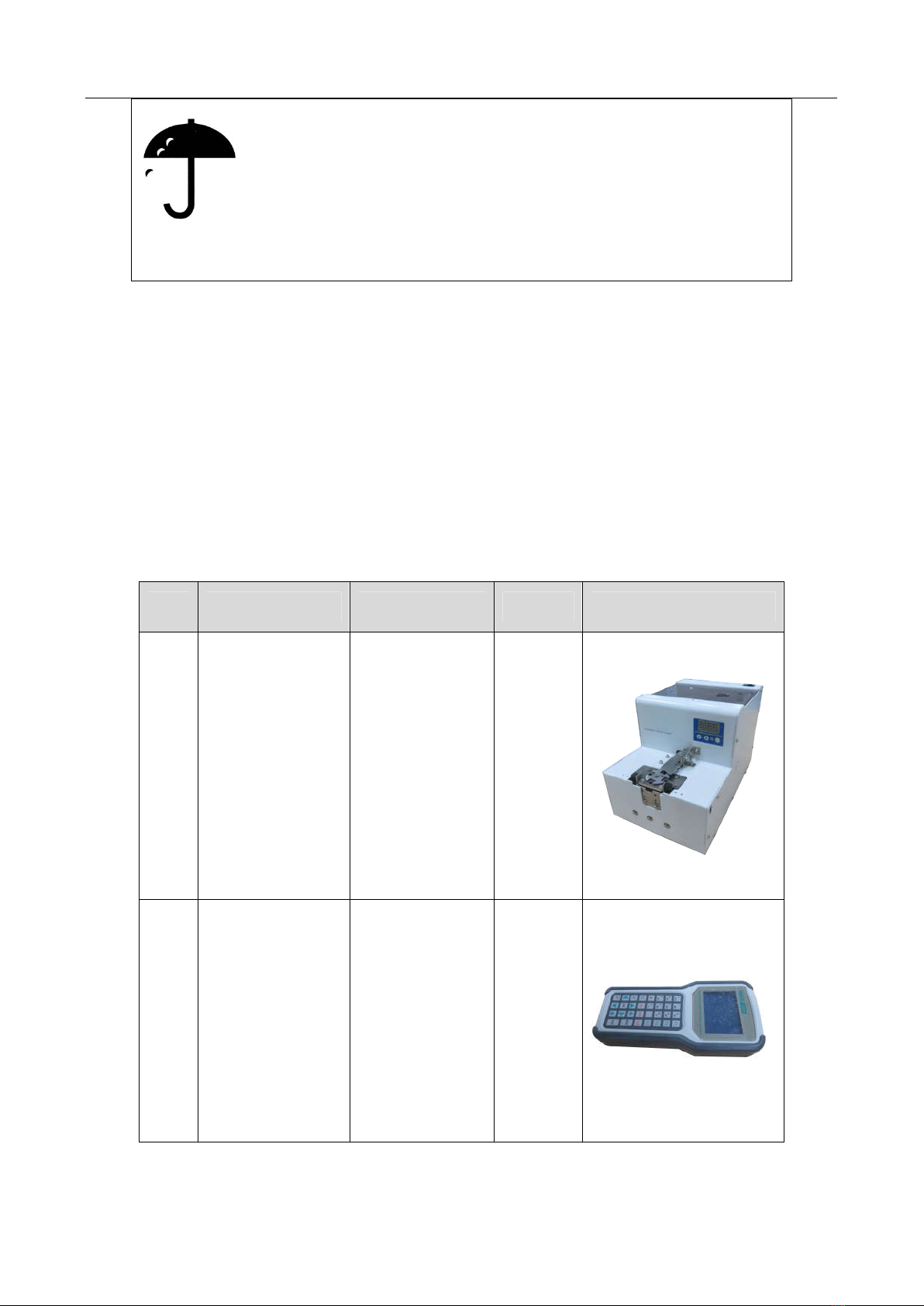
1.2 Unpacking & Inspection ............................................................................................................ 6
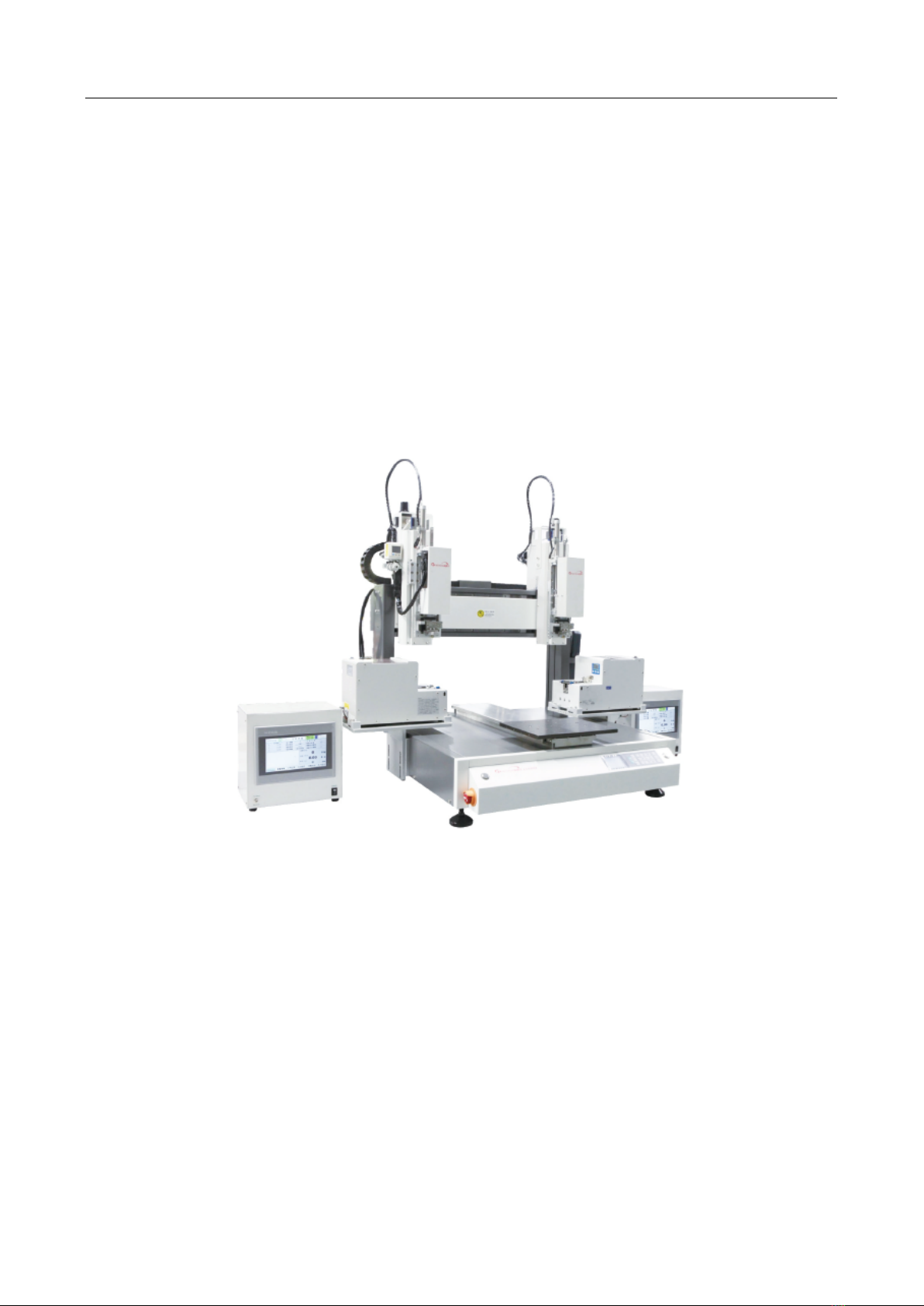
2. Introduction ............................................................................................................................................... 8
2.1 Specifications ............................................................................................................................. 9
2.2 Parts Description ...................................................................................................................... 10
2.3 Dimension .................................................................................................................................11
3. Connection & Use .................................................................................................................................... 12
3.1 Connection ............................................................................................................................... 12
3.2 I/O Socket Instruction .............................................................................................................. 13
3.2.1 Circuit Instruction of I/O Socket ...................................................................................... 13
3.2.2 4-pin Socket Instruction ................................................................................................... 13
3.2.3 5-pin Socket instruction ................................................................................................... 14
3.2.4 6-pin Socket Instruction ................................................................................................... 14
3.2.5 8-pin Socket Instruction ................................................................................................... 15
3.3 Instruction about DB9 Socket .................................................................................................. 16
3.3.1 Pins Instruction of DB9 Socket 1 ..................................................................................... 16
3.3.2 Pins Instruction of DB9 Socket 2 ..................................................................................... 16
3.4 Input & Output Instruction ...................................................................................................... 17
3.4.1 I/O Ports Description ....................................................................................................... 18
3.4.2 I/O Function Instruction ................................................................................................... 20
4. Commissioning ........................................................................................................................................ 22
4.1 Debug Steps ............................................................................................................................. 22
4.1.1 Security Check before Operation ..................................................................................... 22
4.1.2 Operation of First Time .................................................................................................... 23
4.1.3 Set Screwing Position ...................................................................................................... 23
4.2 Interrupt and Continue ............................................................................................................. 26
5. Operation Panel ....................................................................................................................................... 28
5.1 Introduction .............................................................................................................................. 28
5.2 Main Window (with teach pendant) ......................................................................................... 29
5.3 Main Window (disconnect teach pendant cord) ....................................................................... 29
5.3.1 Loop Window .................................................................................................................. 30
5.3.2 S-point Window ............................................................................................................... 31
6. Troubleshooting & Maintenance ............................................................................................................. 32

3
6.1 Troubleshooting ....................................................................................................................... 32
6.2 Daily Check & Maintenance .................................................................................................... 34
6.2.1 Cooling Fan...................................................................................................................... 36
6.2.2 Emergency Stop Button ................................................................................................... 37
6.2.3 Movement Mechanism..................................................................................................... 37
6.2.4 Oil-water Separator .......................................................................................................... 38
6.2.5 Linear Guide .................................................................................................................... 38
6.2.6 Screw Feeder.................................................................................................................... 38
6.2.7 Cleaning ........................................................................................................................... 39

4
1. Safety Instruction
1.1 Symbol Function
Serious warning
The product poses a risk of electric shock.
Only authorized personnel can change settings.
Push the red emergency switch for power off in an emergency situation.
Forbid working while the power wire was damaged.
If the device remains unused for a long time, please pull the power cord out
of power socket.
During maintenance and inspection of the machine, attention power status
and pull out the power plug of the controller.
Install a Frame Ground to prevent electric shock.
There is a dangerous voltage inside the device! Only be authorized by the
experienced and be an expert can repair the equipment, or contact the
agents, manufactures, when the system fails to repair.
Do not plug/unplug cables when the machine powers. If the machine has no
long time be used, please pull out power cable.
Risk for injury.
Do not extend your body when the machine works well or on power up.
Do not wet and disassemble the machine when used. Also do not pull
power cord.
Please keep the machine and table clean, which will help reduce accidents.
Unprofessional can not change arbitrarily. When maintenance, please cut
off the power supply and air pressure.
This product is non-explosion-proof and is strictly prohibited for potential
explosive environment.
Make sure that the heating controller parts are securely fastened to the
machine before using it.
Flammable and explosive objects or gas solvents are strictly prohibited in
the working area.
Warning

5
Do not move the movements by hands to avoid damaging the machine.
Do not touch the moving parts in your work, or you may damage the
machine or accident.
During the operation of the machine, please do not put your hand into the
device, which may cause the user to get injured or cause substantial
damage to the object involved.
During the suspension of the machine, please check the condition carefully
for manual operation, otherwise it may cause the user to get injured or
cause substantial damage to the object involved.
Avoid falling the fittings or having an accident, please take the device and
fittings by help.
Mind head, attention about the sheet metal.
Carry to an applicable place, install the device on a flat floor.
The product must be used or stored in an applicable environment.
Working ambient temperature is 0~40℃
,relative humidity is 20%~90%.
The equipment is heavy and huge, do not pile up.
Do not pile up items in the scope of the machine
Before moving and carrying, make sure the movements is fixed (for
example the X-axis may be fixed by sheet metal or lines for safety).
Unfold the packaging, before using the machine, make sure the
movements’ fixture (for example the X-axis may be fixed by sheet metal or
lines for safety) was torn down.
Regularly inspect and maintain will increase durability and performance.
Must operate the machine by standard procedure.
Before starting a repetitive operation, make sure that there is no obstacle in
the machine’s working area.
Please use machine within the standard requirements (such as voltage, air
pressure, power frequency) as stated in the specification.
Make sure the air source is clean and dry.
Suggest the air pressure is less than 0.7Mpa.
Attention

6
Do not throw the packaging and foamed plastic.
If the machine should come back to the manufacture or agency, it must be
folded by initial package.
The machine must be placed vertically.
The machine can be packet after fold by foamed plastic.
The machine can not get wet in transit or stored procedures.
1.2 Unpacking & Inspection
Wooden case packing:
①Put wooden case packing on the floor vertically, tear up the fixed film.
②Take the screw out of the wooden case by drill and unfold the wooden case.
③Take and carry the device by two or more people, put firmly on appropriate station.
Unfold the packaging, before using the machine, make sure the movements’ fixture (for example the X-axis
may be fixed by sheet metal or lines for safety) is taken down.
④All fittings are in the table as follow.
No. Part Name Model Quantity
Figure
1 Screw feeder ECS66 2pcs
2 Teach pendant 7007 1pcs

7
No. Part Name Model Quantity
Figure
4 Teach pendant cord DB9 1pcs
5 Power cord 1pcs
6 Manual Manual
instructions 1set
7 Key box 8031HA 2pcs
Check the machine carefully, if you have any problem, please contact us immediately!

8
2. Introduction
The automatic locking screw machine is designed to adapt to the automatic direction of fast locking screw. It is a
set of fully three-dimensional and high-precision special motion control equipment. The automatic locking screw
machine needs to be fixed on the motor platform before use, and the machine is programmed. After programming,
press the start button of the automatic locking screw, then the product can be released according to the process.
According to actual production requirement, on the premise of meeting the motion performance index, the
optimized design of product structure, which let the machine work on integration with other agencies, more adapt
to the requirement of automatic locking screw machine.
Comprehensive 3-dimensional drawings support, such as 3-dimensional linear interpolation,
capabilities of teaching 3D graphics and user-defined 3D array and so on.
Group function: This function allows users copy, delete, modify, array, and pan multi-points.
Excellent teach pendant. Supporting advanced function, such as array, group edit, sub-procedure,
condition-call procedure etc.
Unique merge function: Easy resolution to process complex multi-layers irregular array and non-array
graphics.
Smooth functions of changing speed and hi-speed trajectory on the moving. User-definable speed
parameters.
Multiple processing modes, such as single-step operation, overall processing, and automatic loop
processing.
Smooth movement speed ensures product reliability.
Manual debugging, control the whole production process.

9
2.1 Specifications
Equipment Type ET7583Z-TWXBCB95
Input voltage range 220V AC 50/60HZ
Power consumption 500W
Axis number 3
Movement Range (max)
X (mm) 500
Y (mm) 500
Z (mm) 150
R (degree) --
Movement Speed
X (mm/sec) 0.1~1000
Y (mm/sec) 0.1~1000
Z (mm/sec) 0.1~300
R (degree/sec) --
Repeatability X/Y/Z (mm) ±0.01
R (degree) --
Resolution X/Y/Z (mm) 0.01
R (degree) --
Payload Weight(Kg) Z Axis --
Y Axis 8
Demo File Qty. Max 255 files, Max 60000 points
Process File Qty. Max 128 files
Motion Control Motion Control PCBA + Teach Pendant
Noise <70dB(Measure in the distance of 1m)
Operating Ambient Temperature 0~40℃
Humidity 20%~90% (No condensation)
Weight(Kg) 115
Note: Ensure that your power supply data agrees with the information on the nameplate of machine!

10
2.2 Parts Description
Parts name list:
Item Part name Item Part name
1 Left Z axis module 6 Operation panel
2 Left screw feeder 7 Right screwdriver power
supply controller
3 Left screwdriver power
supply controller 8 Right screw feeder
4 Start/Pause button 9 Teach pendant
5 Emergency stop button 10 Right Z axis module
1
2
3
4
5
6
7
8
9
10

11
2.3 Dimension
Front view Left view
Top view 3D view
Unit: mm

12
3. Connection & Use
3.1 Connection
1. Power switch: connect/disconnect the power supply to machine.
2. Power inlet module: connect 220V AC line cord to power inlet module.
3. ESD socket: reliable grounding is essential for screwing machine.
4. DB9 socket 1: Follows RS 232 Standard Communication Protocol, pin’s functions refer to 3.3.1 Pins
Instruction of DB9 Socket 1
5. DB9 socket 2: Follows RS 485 Standard Communication Protocol, pin’s functions refer to 3.3.2 Pins
Instruction of DB9 Socket 2.
6. 5-pin socket: connect to right screwing feeder, refer to 3.2.3 5-pin Socket instruction.
7. 6-pin socket: connect to right screwdriver power supply controller, refer to 3.2.4 6-pin Socket
Instruction.
8. 4-pin socket: connect to key box, refer to 3.2.2 4-pin Socket Instruction.
9. 8-pin socket: spare, refer to 3.2.5 8-pin Socket Instruction.
10. 5-pin socket: connect to left screwing feeder, refer to 3.2.3 5-pin Socket instruction.
11. 6-pin socket: connect to left screwdriver power supply controller, refer to 3.2.4 6-pin Socket
Instruction.
6 8 10
1 2 3 4 5
7
9 11

13
3.2 I/O Socket Instruction
3.2.1 Circuit Instruction of I/O Socket
3.2.2 4-pin Socket Instruction
The following list describes the pins function of the 4-pin socket, it is connected to key box.
4-pin socket Pin Pin Name Description
4P-1 Min4 Connect to “START/PAUSE”
button.
4P-2 GND “0V”
4P-3 Min1 Connect to “ORG” button.
4P-4 Min2 Connect to emergency stop button.

14
3.2.3 5-pin Socket instruction
5-pin socket is connected to left screwing feeder, pin’s functions refer to following table.
5-pin socket Pin Pin Name Description
5P-1 24V “24V” power supply
5P-2 GND “0V”power supply
5P-3 Ein3 Left screw feeder ready signal
5P-4 Ein4 Left screw feeder alarm signal
5P-5 Eout3 Left screw feeder pick screw signal
5-pin socket is connected to right screwing feeder, pin’s functions refer to following table.
5-pin socket Pin Pin Name Description
5P-1 24V “24V” power supply
5P-2 GND “0V”power supply
5P-3 Ein11 Right screw feeder ready signal
5P-4 Ein12 Right screw feeder alarm signal
5P-5 Eout11 Right screw feeder pick screw signal
3.2.4 6-pin Socket Instruction
6-pin socket is connected to left screwdriver power supply controller, pin’s functions refer to following table.
6-pin socket
Pin Pin Name
Description
6P-1 24V “24V” power supply
6P-2 GND “0V”power supply
6P-3 Eout1 Left screwdriver start movement signal
6P-4 Eout2 Left screwdriver fast movement signal
6P-5 Eout4 Left screwdriver reversal movement signal
6P-6 Ein1 Left screwdriver ready signal
6-pin socket is connected to right screwdriver power supply controller, pin’s functions refer to following table.

15
6-pin socket
Pin Pin Name
Description
6P-1 24V “24V” power supply
6P-2 GND “0V”power supply
6P-3 Eout9 Right screwdriver start movement signal
6P-4 Eout10 Right screwdriver fast movement signal
6P-5 Eout12 Right screwdriver reversal movement signal
6P-6 Ein9 Right screwdriver ready signal
3.2.5 8-pin Socket Instruction
8-pin socket is spare socket, pin’s functions refer to following table.
8-pin socket
Pin No.
Pin Name
Function
1
2
3
4
5
68
7
8P-1 24V “24V” power supply
8P-2 GND “0V”power supply
8P-3 Eout14 Reserve
8P-4 Eout15 Reserve
8P-5 Eout16 Reserve
8P-6 Ein14 Reserve
8P-7 Ein15 Reserve
8P-8 Ein16 Reserve
NOTE: * If the customers need special function, the input and output signal can be set again.

16
3.3 Instruction about DB9 Socket
3.3.1 Pins Instruction of DB9 Socket 1
DB9 socket 1 follows Standard RS232 Communication Protocol.
No. Pins
Function No. Pins
Function
1 9P-1
No connection 6 9P-6 No connection
2 9P-2 TX (Transmitter signal ) 7 9P-7 No connection
3 9P-3 RX (Receiver signal) 8 9P-8 No connection
4 9P-4 No connection 9 9P-9 No connection
5 9P-5 GND ( “0V”)
3.3.2 Pins Instruction of DB9 Socket 2
DB9 socket 2 follows Standard RS485 Communication Protocol.
No. Pins
Function No. Pins
Function
1 9P-1
No connection 6 9P-6 No connection
2 9P-2 No connection 7 9P-7 2-485A

17
No. Pins
Function No. Pins
Function
3 9P-3 No connection 8 9P-8 2-485B
4 9P-4 No connection 9 9P-9 No connection
5 9P-5 No connection
3.4 Input & Output Instruction
The following input interfaces and output interfaces are corresponding to the signal pins which are defined as
“Min, Mout, Ein, Eout” at the above socket. Also, it is corresponding to the interface at the “IO Test”
displaying window. After setting, it can test the function of IO interface at the “IO Test” displaying window.
The interfaces in following table can be set at the “Input Configuration” or “Output Configuration” of
“System Configuration 2” of teaching pendant.
It can define the special function for the following input & output interfaces which are corresponding to the
above sockets.
Main board port define list:
Port Description Port Description
Mout1 Left vacuum suction signal Min1 Reset signal
Mout2 Left screwdriver down signal Min2 Emergency stop signal
Mout3 Right vacuum suction signal Min3 Safety signal
Mout4 Right screwdriver down signal
Min4 Left start signal
Mout5 Solenoid valve 1 Min5 Reserve
Eout1 Left screwdriver start
movement signal Ein1 Left screwdriver ready signal
Eout2 Left screwdriver fast
movement signal Ein2 Left pressure detection sensor
Eout3 Left screw feeder pick screw
signal Ein3 Left screw feeder ready signal
Eout4 Left screwdriver reversal
movement signal Ein4 Left screw feeder alarm signal
Eout5 Buzzer/light house Ein5 Reserve
Eout6 Green light/light house Ein6 Reserve

18
Port Description Port Description
Eout7 Yellow light/light house Ein7 Reserve
Eout8 Red light/light house Ein8 Reserve
Eout9 Right screwdriver start
movement signal Ein9 Right screwdriver ready signal
Eout10 Right screwdriver fast
movement signal Ein10 Right pressure detection
sensor
Eout11 Right screw feeder pick screw
signal Ein11 Right screw feeder ready
signal
Eout12 Right screwdriver reversal
movement signal Ein12 Right screw feeder alarm
signal
Eout13 Solenoid valve 2 Ein13 Solenoid valve 3
Eout14 8P-6 Ein14 8P-3
Eout15 8P-7 Ein15 8P-4
Eout16 8P-68 Ein16 (8P-5)right Start button
3.4.1 I/O Ports Description
1. In the “Input Configuration ” displaying window, it can set the input interface:Min1~Min4、Ein1-8、
Ein09~Ein16.
Input Interface
Optional Function
Min1 --, Shortcut001, Origin BTN, Test input-1,Test input-2
Min2 --, Shortcut 002, Stop BTN, Test input-1,Test input-2
Min3 --, Shortcut003, Start BTN, Test input-1,Test input-2, Block fault, Upper CS, Nether CS
Min4 --, Shortcut 004, Foot BTN, Test input-1,Test input-2
Ein1~Ein8 --, Shortcut 5-259
Ein01-Ein04 --
Ein05 --, Origin BTN, Stop BTN, Start BTN, Foot BTN, Test input-1, Test input-2, Shortcut
009, Lack fault, Air fault
Ein06 --, Origin BTN, Stop BTN, Start BTN, Foot BTN, Test input-1,Test input-2, Shortcut
010, Lack fault, Air fault
Ein07 --, Origin BTN, Stop BTN, Start BTN, Foot BTN, Test input-1,Test input-2, Shortcut
011, Lack fault, Air fault
Ein08 --, Origin BTN, Stop BTN, Start BTN, Foot BTN, Test input-1,Test input-2, Shortcut
011, Lack fault, Air fault

19
Input Interface
Optional Function
Ein09-Ein12 --,
Ein13 --, Origin BTN, Stop BTN, Start BTN, Foot BTN, Test input-1,Test input-2, Shortcut
264, Lack fault, Upper CS, Nether CS, Air fault
Ein14 --, Origin BTN, Stop BTN, Start BTN, Foot BTN, Test input-1,Test input-2, Shortcut
265, Lack fault, Upper CS, Nether CS, Air fault
Ein15 --, Origin BTN, Stop BTN, Start BTN, Foot BTN, Test input-1,Test input-2, Shortcut
266, Lack fault, Upper CS, Nether CS, Air fault
Ein16 --, Origin BTN, Stop BTN, Start BTN, Foot BTN, Test input-1,Test input-2, Shortcut
267, Lack fault, Upper CS, Nether CS, Air fault
Kin1-Kin4 --
2. In the “Output Configuration ” displaying window, it can set the output interface: Mout1~Mout4、
Eout09~Eout12、Eout13~Eout16.
Output Interface
Optional Function
Mout1~Mout4 --
Eout09~Eout12 --
Eou13-Eou16 --, Ready Flag, Alarm Flag, Working Flag, WorkEnd Flag, Cylinder, Clean Output,
Lock alarm, Lock error
3. In the teach pendant, “Eout09~Eout16” are corresponding to the “Eout8+ (0~8)” at the “IO Test” and
“Output (point)” displaying window.
Namely: “Eout8+ 1” is the expansion output interface “Eou09”. “Eout8+ 2” is the expansion output interface
“Eou10”. “Eout8+3” is the expansion output interface Eout11, by parity of reasoning.
“Ein8+1” is the expansion input interface Ein09,“Ein8+2” is the expansion input interface Ein10,
“Ein8+3” is the expansion input interface Ein11, by parity of reasoning.
This manual suits for next models
1
Table of contents
Popular Industrial Equipment manuals by other brands

RIDGID
RIDGID 141 Operator's manual

Rexnord
Rexnord Falk Steelflex T10 Installation and maintenance instructions

Propex
Propex Pyramat Series Installation and Maintenance

ROLEC
ROLEC MARINA SmartVend SVCS0010 Installation & operation manual

Bushranger
Bushranger SNATCH BLOCK quick start guide

Texas Instruments
Texas Instruments DRV2604LDGS user guide