Vector Pro PWA-14 Guide

ISSUED: 03-19-03 SHEET #: 017-9011-4 06-13-07
Visit the Peerless Web Site at www.peerlessmounts.com For customer service call 1-800-729-0307 or 708-865-8870.
1 of 6
Installation and Assembly - Vector Pro™and PRS Projector
Wall Mounts
Models: PWA-14,
PWA-14S,
PWA-14W
• Thisproductwasdesignedandintendedtobemountedtothefollowingsupportingsurfacescheckedbelowwith
the hardware included in this product as specified in the installation sheet.To mount this product to an alterna-
tivesupportingsurface,contactPeerlesscustomercareat1800865-2112.
• This product was designed to be installed on the following wall construction only;
WALLCONSTRUCTION ADDITIONALHARDWARE REQUIRED
xWoodStud None
xWoodBeam None
SolidConcrete Do not attach except with Peerless accessory kit for solid concrete;
Contact Customer Service for Peerless accessory kit for solid concrete.
CinderBlock Do not attach except with Peerless accessory kit for cinder block;
Contact Customer Service for Peerless accessory kit for cinder block.
MetalStud Do not attach except with Peerless accessory kit for metal studs;
Contact Customer Service for Peerless accessory kit for metal studs.
Brick ContactCustomerService
Otherorunsure? Contact Customer Service
WARNING
Max. Load Capacity
50 lb (22.7 kg)
Some of the following
tools may be required:
Drill, hammer, socket
wrench, pencil, stud finder
IMPORTANT! Read entire instruction sheet before you start installation and assembly.
IMPORTANT! Certain types of walls require additional mounting hardware...
TURN TO THE APPROPRIATE PAGE FOR YOUR INSTALLATION.
Installations:
ToWoodStud Walls..............................................................step 2,page 3
ToConcrete Walls...................................................................step3,page4
ToMetalStudWalls.................................................................step4,page5

ISSUED: 03-19-03 SHEET #: 017-9011-4 06-13-07
Visit the Peerless Web Site at www.peerlessmounts.com For customer service call 1-800-729-0307 or 708-865-8870.
2 of 6
D
B
G
E
C
H
A
A
B
C
D
E
F
G
H
Description
support arm
carriage bolt
M10 locknut
M10 steel washer
M10 bronze washer
#14 x 2.5 phillips wood screw
threaded rod adapter
end cap
Qty.
1
1
1
1
1
2
1
1
Parts List
Part #
017-1019
580-1022
530-9402
540-9407
540-9441
5S1-015-C03
580-1021
590-1014
Some parts may appear slightly different
than illustrated.
F
Attach threaded rod adapter (G) to
support arm (A) using carriage bolt
(B), locknut (C), steel washer (D) and
bronze washer (E) as shown. Insert
end cap (H) into end of support arm
(A) as shown.
Part #
017-4019
580-2022
530-9404
540-9470
540-9441
5S1-015-C04
580-2021
590-4014
Part #
017-2019
580-2022
530-9404
540-9470
540-9441
5S1-015-C04
580-2021
590-1001
Model # PWA-14 PWA-14S PWA-14W

ISSUED: 03-19-03 SHEET #: 017-9011-4 06-13-07
Visit the Peerless Web Site at www.peerlessmounts.com For customer service call 1-800-729-0307 or 708-865-8870.
3 of 6
∅ 5/32"
(4 mm)
Drill two 5/32" (4 mm) dia. holes 2 1/2" (65 mm) deep. Attach wall
arm (A) with #14 x 2.5"(6 mm x 65 mm) wood screws (F).
F
A
∅ 5/32"(4 mm)
A
Installation to a wood stud wall
• Tighten wood screws so that wall plate is firmly
attached,butdonot overtighten. Overtightening can
damagethescrews,greatlyreducingtheirholding
power.
• Never tighten in excess of 80 in • lb (9 N.M.).
• Make sure that mounting screws are anchored into the
center of the studs. The use of an "edge to edge" stud
finderishighlyrecommended.
WARNING

ISSUED: 03-19-03 SHEET #: 017-9011-4 06-13-07
Visit the Peerless Web Site at www.peerlessmounts.com For customer service call 1-800-729-0307 or 708-865-8870.
4 of 6
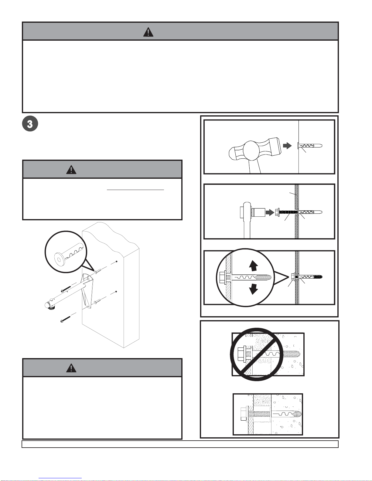
Installation to a concrete wall
Drill two 1/4" (6 mm) dia. holes to a minimum depth of
2.5" (64 mm). Attach support arm (A) using concrete
anchors(call customer service to order accessory kit ACC
200 or ACC203)and #14 x 2.5" wood screws (F) as
shown in Illustration A and 1, 2, and 3. Tighten all
fasteners.
1
3
Drill hole and insert anchor
Place wall plate over anchor and secure with screw
After repeating step one tighten all fasteners
CUTAWAYVIEW
INCORRECT
concrete
metal
bracket
plaster/
drywall
CORRECT
concrete
metal
bracket
plaster/
drywall
concrete
wall
concrete
anchor
concrete
anchor
concrete
anchor
F
F
2A
WARNING
• When installing Peerless wall mounts on cinder block, verify that you have a minimum of 1-3/8" of actual concrete
surface in the hole to be used for the concrete anchors. Do not drill into mortar joints! Be sure to mount in a solid
part of the block, generally 1" minimum from the side of the block. Cinder block must meetASTM C-90 specifica-
tions. It is suggested that a standard electric drill on slow setting is used to drill the hole instead of a hammer drill
toavoidbreakingoutthebackof the hole when entering a void or cavity.
• Concrete must be 2000 psi density minimum. Lighter density concrete may not hold concrete anchor.
• Make sure that the wall will safely support four times the combined load of the equipment and all attached hard-
wareandcomponents.
• Tighten wood screws firmly, but do not overtighten.
Overtighteningcandamagethescrews, greatly
reducingtheirholding power.
• Never tighten in excess of 80 in • lb (9 N.M.).
WARNING
• Concrete anchorsare not intendedfor attachment to
concretewallcoveredwithalayerofplaster,drywall,
orotherfinishingmaterial.Ifmountingtoconcretewall
coveredwithplaster/drywallis unavoidable, plaster/
drywall (up to 5/8" thick) must be counterbored as
shown right. If plaster/drywall is thicker than 5/8",
custom fasteners must be supplied by installer.
WARNING
concrete
anchor
F
A
Illustration A

ISSUED: 03-19-03 SHEET #: 017-9011-4 06-13-07
Visit the Peerless Web Site at www.peerlessmounts.com For customer service call 1-800-729-0307 or 708-865-8870.
5 of 6
∅ 1/2"(13 mm)
Push into hole.
Drill 1/2" (13 mm) dia. holes through drywall and
stud. Insert togglers (call customer service to order
accessory kit ACC 415) as follows.
Important: Product must be mounted through
drywall that has a minimum thickness of 1/2" and
into metal studs, 26 gauge or heavier.
Pivot end of toggler.
Slide plastic cap forward while pulling back firmly on ring.
Snap off as shown.
Attach wall arm with 1/4-20 phillips
screws.
toggler
Installation to a metal stud wall
A
• Product must be mounted through drywall that has a
minimum thickness of 1/2" and into metal studs, 26
gaugeorheavier.
WARNING
1/4-20 x 2.5"
phillips screw

ISSUED: 03-19-03 SHEET #: 017-9011-4 06-13-07
Visit the Peerless Web Site at www.peerlessmounts.com For customer service call 1-800-729-0307 or 708-865-8870.
6 of 6
Thread projector mount onto threaded rod adapter
(G) as shown. Note: Make sure the notch in
threaded rod adapter (G) is aligned with one of the
four holes at the top of the PJF2-1.
G
PJF2-1 (not included)
PRS-1 (not shown)
Secure PJF2-1 to threaded rod adapter (G) with one
#10-32 x 3/8 socket pin screw provided with PJF2-1
#10-32 x 3/8 socket pin screw
Refer to PJF2-1 or PRS-1 model instructions for attachment of projector.
©2004PeerlessIndustries,Inc. Allrightsreserved.
PeerlessisaregisteredtrademarkofPeerlessIndustries,Inc.
Allotherbrandandproductnamesaretrademarksorregisteredtrademarksoftheirrespectiveowners.
Note: Installation of PRS-1 not shown. Please
refer to PRS model instructions to attach PRS
mount to PWA-14.
Note: Installation PRS-1 not shown. Please refer
to PRS model instructions to attach PRS mount to
PWA-14.
This manual suits for next models
2
Table of contents
Popular Projector Accessories manuals by other brands

Black Box
Black Box WC-COA-MPE user manual

Fromm&Starck
Fromm&Starck STAR PMW 01 user manual

Omnimount
Omnimount WM3-PJT instruction manual

Omnimount
Omnimount PMD-1 installation instructions

Stewart Filmscreen
Stewart Filmscreen AVS-1005 owner's manual

EliteProAV
EliteProAV Yard Master Electric Series user guide