Vega VEGAPULS 51K User manual

Operating Instructions
VEGAPULS 51K … 54K
4 … 20 mA; HART®compact sensor

2VEGAPULS 51K … 54K
21750-EN-031222
Contents
Contents
Safety information ........................................................................ 3
Note Ex area ................................................................................ 3
1 Product description .................................................................. 4
1.1 Function ................................................................................. 4
1.2 Application features ............................................................. 5
1.3 Adjustment ............................................................................ 6
2 Types and versions ................................................................... 8
2.1 Overview .............................................................................. 8
2.2 Antennas ............................................................................. 10
3 Mounting and installation ..................................................... 11
3.1 General installation instructions ........................................ 11
3.2 Measurement of liquids ..................................................... 12
3.3 Measurement in standpipe (surge or bypass tube) ...... 14
3.4 False echoes ...................................................................... 21
3.5 Common installation mistakes ........................................... 23
4 Electrical connection .............................................................. 25
4.1 Connection and connection cable .................................... 25
4.2 Connecting the sensor ...................................................... 27
4.3 Connecting of the external indicating instrument
VEGADIS 50 ....................................................................... 31
4.4 Configuration of measuring systems ............................... 32
5 Set-up ........................................................................................ 40
5.1 Adjustment media .............................................................. 40
5.2 Adjustment with PC ............................................................ 40
5.3 Adjustment with adjustment module MINICOM ............... 42
5.4 Adjustment with HART® handheld ................................... 48
6 Diagnostics............................................................................... 50
6.1 Simulation ............................................................................ 50
6.2 Error codes ........................................................................ 50

VEGAPULS 51K … 54K 3
21750-EN-031222
Contents
7 Technical data .......................................................................... 51
7.1 Technical data ..................................................................... 51
7.2 Approvals ........................................................................... 58
7.3 Dimensions ......................................................................... 59
Supplement ..................................................................................... 63
Safety Manual ................................................................................. 63
1 General ............................................................................... 63
1.1 Validity ................................................................................. 63
1.2 Area of application ............................................................... 63
1.3 Relevant standards ............................................................. 63
1.4 Determination of safety-related characteristics .................. 64
2 Planning .............................................................................. 65
2.1 Low demand mode ............................................................... 65
2.2 High demand or continuous mode ....................................... 65
2.3 General ................................................................................ 65
3 Set-up ................................................................................. 66
3.1 Mounting and installation ..................................................... 66
3.2 Adjustment instructions and parameter adjustment ........... 66
3.3 Configuration of the processing unit ................................... 66
4 Reaction during operation and in case of failure ............. 67
5 Recurring function test ....................................................... 67
6 Safety-related characteristics ........................................... 68
SIL declaration of conformity .................................................... 69
CE declaration of conformity ..................................................... 70
Safety information
Please read this manual carefully, and also take
note of country-specific installation standards
(e.g. the VDE regulations in Germany) as well
as all prevailing safety regulations and acci-
dent prevention rules.
For safety and warranty reasons, any internal
work on the instruments, apart from that in-
volved in normal installation and electrical con-
nection, must be carried out only by qualified
VEGA personnel.
Note Ex area
Please note the attached safety instructions
containing important information on installation
and operation in Ex areas.
These safety instructions are part of the oper-
ating instructions manual and come with the Ex
approved instruments.

4VEGAPULS 51K … 54K
21750-EN-031222
Product description
emission - reflection - reception
Meas.
distance
1 Product description
1.1 Function
Radio detecting and ranging: Radar.
VEGAPULS radar sensors are used for non-
contact, continuous distance measurement.
The measured distance corresponds to a
filling height and is outputted as level.
Measuring principle:
emission – reflection – reception
Extremely small 5.8 GHz radar signals are
emitted from the antenna of the radar sensor
as short pulses. The radar pulses reflected
by the sensor environment and the product
are received by the antenna as radar ech-
oes. The running period of the radar pulses
from emission to reception is proportional to
the distance and hence to the level.
The radar pulses are emitted by the antenna
system as pulse packages with a pulse
duration of 1 ns and pulse intervals of
278 ns; this corresponds to a pulse package
frequency of 3.6 MHz. In the impulse inter-
vals, the antenna system operates as a re-
ceiver. Signal running periods of less than
one billionth of a second must be processed
and the echo image evaluated in a fraction of
a second.
1 ns
278 ns
Pulse sequence
VEGAPULS radar sensors can achieve this
through a special time transformation proce-
dure which spreads out the more than 3.6
million echo images per second into a quasi
slow-motion picture, then freezes and proc-
esses them.
tt
Time transformation
Hence, it is possible for the radar sensors to
process the slow-motion pictures of the sen-
sor environment precisely and in detail in
cycles of 0.5 to 1 second without using time-
consuming frequency analysis (e.g. FMCW,
required by other radar techniques).
Virtually all products can be measured
Radar signals display physical properties
similar to those of visible light. According to
the quantum theory, they propagate through
empty space. Hence, they are not depend-
ent on a conductive medium (air), and they
spread out like light at the speed of light.
Radar signals react to two basic electrical
properties:
- the electrical conductivity of a substance
- the dielectric constant of a substance.

VEGAPULS 51K … 54K 5
21750-EN-031222
Reflected radar power dependent on the dielectric
constant of the measured product
2
0
0
10
25 %
40 %
5
10
5 %
20
30
40
50
%
4 6 8 12 14 16 18
20
εr
Product description
All products which are electrically conductive
reflect radar signals very well. Even slightly
conductive products provide a sufficiently
strong reflection for a reliable measurement.
All products with a dielectric constant εr
greater than 2.0 reflect radar pulses suffi-
ciently (note: air has a dielectric constant εr of
1). Signal reflectivity grows stronger with
increasing conductivity or increasing dielec-
tric constant of the product. Hence, nearly all
substances can be measured.
Temperature influence: Temperature error absolutely
zero (e.g. at 500°C 0.018 %)
100 500 1000 1300 ˚C
0
0
0,01
0,02
0,03
%
0,018 % 0,023 %
Pressure influence: Error with pressure increase very
low (e.g. at 50 bar 1.44 %)
10
0
0
5
%
1,44 % 2,8 %
10
50
20 30 40 60 100
70 80 90 110 120 130 140 bar
0,29 %
3,89 %
With standard flanges of DN 50 to DN 250,
ANSI 2“ up to ANSI 10“ or G 1½ A and 1½“
NPT, the sensor antenna systems can be
adapted to various products and measuring
environments.
The high-quality materials can also withstand
extreme chemical and physical conditions.
The sensors deliver stable, reproducible
analogue or digital level signals with reliability
and precision and have a long useful life.
Continuous and accurate
Unaffected by temperature, pressure and
atmosphere content, VEGAPULS radar sen-
sors measure quickly, accurately and con-
tinuously the levels of widely varying
products.
VEGAPULS 50 sensors allow radar level
measurement in plants where it was hitherto
unthinkable because of high costs.
1.2 Application features
Applications
• level measurement of any liquid, limited in
solids.
• measurement also in vacuum
• all slightly conductive materials and all
substances with a dielectric constant > 2.0
can be measured
• measuring range 0 … 20 m.
Two-wire technology
• power supply and output signal on one
two-wire cable (Loop powered)
• 4 … 20 mA output signal or HART® output
signal.
Rugged and abrasionproof
• non-contact
• high-resistance materials
Exact and reliable
• accuracy 1 mm.
• unaffected by noise, vapours, dusts, gas
compositions and inert gas stratification
• unaffected by varying density and tem-
perature of the medium
• measurement in pressures up to 40 bar
and product temperatures up to 200 °C.

6VEGAPULS 51K … 54K
21750-EN-031222
Adjustment with the PC on the 4 … 20 mA signal and
supply cable or directly on the sensor (figure: a two-
wire sensor)
PLC
The PC can be connected at any location in
the system or directly to the signal cable. It is
connected by means of the two-wire PC
interface converter VEGACONNECT 3 to the
sensor or the signal cable. The adjustment
and parameter data can be saved with the
adjustment software on the PC and can be
protected by passwords. On request, the
adjustments can be quickly transferred to
other sensors.
2
2
1.3 Adjustment
Every measurement setup is unique. For that
reason, every radar sensor needs some
basic information on the application and the
environment, e.g. which level means "empty“
and which level "full“. Beside this "empty and
full adjustment“, many other settings and
adjustments are possible with VEGAPULS
radar sensors.
The adjustment and parameter setting of
radar sensors is carried out with
- the PC
- the detachable adjustment module MINI-
COM
- the HART® handheld
Adjustment with the PC
The set-up and adjustment of the radar sen-
sors is generally done on the PC with the
adjustment software PACT
ware
TM.The pro-
gram leads quickly through the adjustment
and parameter setting by means of pictures,
graphics and process visualisations.
Adjustment with the PC on the analogue 4 … 20 mA
signal and supply cable or directly on the sensor
(four-wire sensor)
Product description
2
2
4 ...20 mA
Communicative
• integrated measured value display
• optional display module separate from
sensor
• adjustment with detachable adjustment
module, pluggable in the sensor or in the
external display
• adjustment with HART®handheld
• adjustment from PLC level with the PC
Approvals
• CENELEC, ATEX, PTB, FM, CSA, ABS,
LRS, GL, LR, FCC.

VEGAPULS 51K … 54K 7
21750-EN-031222
HART®handheld on the 4 … 20 mA signal cable
To make adjustments, simply connect the
HART®handheld to the 4 … 20 mA output
signal cable or insert the two communication
cables of the HART® handheld into the ad-
justment jacks on the sensor.
HART®handheld
HART Communicator
Adjustment with the HART®handheld
Series 50 sensors with 4 … 20 mA output
signal can also be adjusted with the HART®
handheld. A special DDD (Data Device De-
scription) is not necessary - the sensors can
be adjusted with the HART®standard menus
of the handheld.
2
24 ...20 mA
Adjustment with detachable adjustment module. The
adjustment module can be plugged into the radar
sensor or into the external indicating instrument
VEGADIS 50.
Detachable adjustment module MINICOM
-+ESC
OK
Tank 1
m (d)
12.345
Adjustment with the adjustment module
MINICOM
With the small (3.2 cm x 6.7 cm) 6-key ad-
justment module with display, the adjustment
is carried out in clear text dialogue. The ad-
justment module can be plugged into the
radar sensor or into the optional, external
indicating instrument.
Unauthorised sensor adjustments can be
prevented by removing the adjustment mod-
ule.
-+
ESC
OK
2
4
Tank 1
m (d)
12.345
-+
ESC
OK
Tank 1
m (d)
12.345
4 ... 20 mA
Product description

8VEGAPULS 51K … 54K
21750-EN-031222
Types and versions
2 Types and versions
2.1 Overview
VEGAPULS series 50 sensors are a newly
developed generation of very compact, small
radar sensors. With modest space require-
ments, they were developed for short meas-
uring distances of 0 … 20 m and for
standard applications such as storage tanks
and buffer tanks, but also for process ves-
sels.
Due to their small housing dimensions and
process connections, the compact sensors
do your level monitoring inconspicuously, and
above all, at reasonable cost. With their inte-
grated display and remarkable intelligence,
they bring the advantages of radar level
measurement to applications where previ-
ously, due to high cost, the advantages of
non-contact measurement had to be fore-
gone.
VEGAPULS 50 radar sensors utilise two-wire
technology perfectly. The supply voltage and
the output signal are transmitted via one two-
wire cable. They provide an analogue
4 … 20 mA output signal as output or meas-
uring signal.
VEGAPULS 51/52
VEGAPULS 53
VEGAPULS 54
(pipe antenna/
standpipe)
VEGAPULS 54
(pipe antenna/
standpipe)

VEGAPULS 51K … 54K 9
21750-EN-031222
Types and versions
Features
General features
• Application preferably for liquids in storage tanks.
• Measuring range 0 … 20 m.
• Ex approved in Zone 1 (IEC) or Zone 1 (ATEX) classification mark
EEx ia [ia] IIC T6.
• Integrated measured value display.
Survey
VEGAPULS …
51K 52K 53K 54K
Signal output
- active (4 … 20 mA) • • • •
- passive (4 … 20 mA) • • • •
Voltage output
- two-wire technology (power
supply and signal output
via one two-wire cable) • • • •
- four-wire technology (power
supply separate from the signal
cable) • • • •
Process fitting
- G1½ A; 1½“ NPT • • – –
- DN 50; ANSI 2“ – – • •
- DN 80; ANSI 3“ – – • •
- DN 100; ANSI 4“ – – • •
- DN 150; ANSI 6“ – – • •
Adjustment
-PC • • • •
- adjustment module in the sensor • • • •
- adjustment module in external
indicating instrument • • • •
- HART®handheld • • • •
Antenna material
- PP/PVDF • – – –
- PPS/StSt • – – –
- PTFE/PVDF – • – –
- PTFE/StSt – • – –
- PTFE – – • –
- StSt/PTFE – – – •
- Hastelloy C22/PTFE – – – •

10 VEGAPULS 51K … 54K
21750-EN-031222
Types and versions
2.2 Antennas
The antenna is the eye of the radar sensor.
The shape of the antenna, however, doesn’t
give a casual observer the slightest clue on
how carefully the antenna geometry must be
adapted to the physical properties of electro-
magnetic waves. The geometrical form deter-
mines focal properties and sensitivity - the
same way it determines the sensitivity of a
unidirectional microphone.
Four antenna systems are available for differ-
ent applications and process requirements.
Beside having its own unique focusing char-
acteristics, each system differs in its chemi-
cal and physical properties.
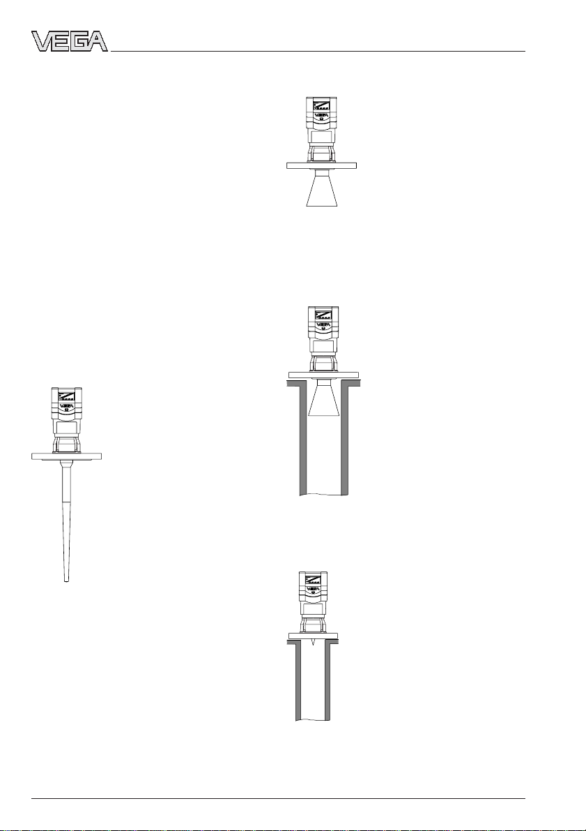
Rod antenna
Rod antennas with high chemi-
cal resistance require only the
very smallest flange diameters
(DN 50). The antenna rod and
the wetted flange parts are
made of PTFE, PP or PPS so
that the rod antenna can be
easily cleaned and provide
resistance to condensation.
The rod antenna is suitable for
pressures up to 16 bar and
temperatures up to 150 °C.
Horn antenna
Horn antennas are well suited
for most applications. They
focus the radar signals very
well. Manufactured of 1.4571
(StSt) or Hastelloy C22, they
are very rugged and are
physically as well as chemi-
cally resistant. They are suit-
able for pressures up to
40 bar and for product tem-
peratures up to 150 °C.
Pipe antenna
The pipe antennas on surge
or bypass tubes only form a
complete antenna system in
conjunction with a measuring
tube (which can also be
curved). Pipe antennas are
especially suitable for prod-
ucts with strong flow or tur-
bulence, or products with low
dielectric constant.
The antenna is available with
or without a horn. Versions
with horn are characterised
by a very high antenna gain.
High measurement reliability
can thus be achieved even in products with
very poor reflective properties.
The measuring tube acts as a
conductor for radar signals.
The running period of the radar
signals changes in the tube and
depends on the tube diameter.
The tube inner diameter must
be programmed in the sensor
so that it can take the altered
running time into account and
deliver accurate level signals.

VEGAPULS 51K … 54K 11
21750-EN-031222
Mounting and installation
Measuring range (operating range) and max. measuring distance
Note: Use of the sensors for applications with solids is limited.
3 Mounting and installation
3.1 General installation instructions
Measuring range
The reference plane for the measuring range
of the sensor is the lower edge of the flange
or the seal shoulder of the thread
(VEGAPULS 51, 52). The measuring range is
0 … 20 m. When measuring in a surge or
bypass tube (pipe antenna), the max. meas-
uring distance is reduced.
Keep in mind that in measuring environments
where the medium can reach the sensor
flange, buildup may form on the antenna and
later cause measurement errors.
Note: The series 50 sensors are suitable for
measurement of solids only under certain
conditions.
Profiles with flat interfering surfaces cause large
false signals
Round profiles diffuse radar signals
Cover smooth interfering surfaces with deflectors
False echoes
Flat obstructions and struts cause strong
false echoes. They reflect the radar signal
with high energy density.
Interfering surfaces with rounded profiles
scatter the radar signals into the surrounding
space more diffusely and thus generate false
echoes with a lower energy density. Hence,
those reflections are less critical than those
from a flat surface.
If flat obstructions in the range of the radar
signals cannot be avoided, we recommend
diverting the interfering signals with a deflec-
tor. The deflector prevents the interfering
signals from taking a direct path back to the
radar sensor. The signals are then so low-
energy and diffuse that they can be filtered
out by the sensor.
empty
Meas. range
max. meas. distance 20 m
Reference plane full
4 m
16 m
max.
max.
max.
max. filling

12 VEGAPULS 51K … 54K
21750-EN-031222
Mounting on DIN socket piece
In vessels with dished or rounded tops, the
antenna length should at least correspond to
the length of the longer sockets.
Mounting on a dished vessel top
3.2 Measurement of liquids
Flange antennas
Horn antenna on DIN socket piece
Radar sensors are usually mounted on short
DIN socket pieces. The lower side of the
instrument flange is the reference plane for
the measuring range. The antenna should
always protrude out of the flange pipe.
If the DIN socket piece is longer, make sure
that the horn antenna does not appear in the
socket opening.Better results are achieved
when the antenna protrudes at least 10 mm
out of the socket.
Vessel center or
symmetric axis
> 10 mm
> 10 mm
Reference plane
Mounting and installation
Emission cone and false reflections
The radar signals are focused by the an-
tenna system. The signals leave the antenna
in a conical path similar to the beam pattern
of a spotlight. This emission cone depends
on the antenna used. Any object in this beam
cone causes a reflection of the radar signals.
Within the first few meters of the beam cone,
tubes, struts or other installations can inter-
fere with the measurement. At a distance of 6
m, the false echo of a strut has an amplitude
nine times greater than that at a distance of
18 m.
At greater distances, the energy of the radar
signal distributes itself over a larger area,
thus causing weaker echoes from obstruct-
ing surfaces. The interfering signals are
therefore less critical than those at close
range.
Make sure the sensor axis is perpendicular
to the product surface and avoid, if possible,
vessel installations (e.g. pipes and struts)
within the 50 % area of the emission cone.
The illustrations of the emission cone are
simplified and represent only the main beam
- a number of weaker beams also exists.
Under difficult measuring conditions, the
antenna alignment must be selected with the
objective of reaching the lowest possible
echo intensity. Only giving attention to the
size of the useful echo is not adequate when
measuring conditions are unfavourable.
In difficult measuring environments, search-
ing for a mounting location with the lowest
possible false echo intensity will bring the
best results. In most cases, the useful echo
will then be present with sufficient strength.
With the adjustment software PACTwareTM on
the PC, you can have a look at the echo im-
age and optimise the mounting location (see
chapter „5.2 Adjustment with the PC – Sensor
optimisation – Echo curve“).
If possible, provide a „clear view" of the
product inside the emission cone and avoid
vessel installations in the first third of the
emission cone.
Optimum measuring conditions exist when
the emission cone reaches the measured
product perpendicularly and when it is free of
obstructions.

VEGAPULS 51K … 54K 13
21750-EN-031222
Mounting and installation
Mounting directly on the flat vessel top
Reference plane
Mounting on round vessel tops
Reference plane
½ vessel radius
Horn antenna directly on the vessel top
If the stability of the vessel will allow it (sensor
weight), flat mounting directly on the vessel
top is a good and cost-effective solution. The
top side of the vessel is the reference plane.
Rod antenna
Rod antenna on DIN socket piece
The PTFE (Teflon) rod antenna is well suited
to chemically aggressive products such as
lyes and acids. Applications in the food
processing industry with aseptic vessel
conditions require nonreactive measuring
systems and very small vessel openings.
The Teflon rod antenna is not only
nonreactive, but can be mounted in very
small vessel openings (50 mm or 1½“ thread
holes).
For measurements of liquids, the Teflon rod
antenna is mounted on a straight DIN socket
piece. The socket however must not be
longer than 150 mm (when using the longer
antenna, not longer than 250 mm). The rod
antenna is available in flange sizes of DN 50,
DN 80 and DN 100.
On dished tank ends, please do not mount
the instrument in the centre or close to the
vessel wall, but approx. ½ vessel radius from
the centre or from the vessel wall.
Dished tank ends can act as paraboloidal
reflectors. If the radar sensor is placed in the
focal point of the parabolic tank, the radar
sensor receives amplified false echoes. The
radar sensor should be mounted outside the
focal point. Parabolically amplified echoes are
thereby avoided.
Rod antenna on DIN socket piece
≤50 mm, 100 mm or
250 mm
Vessel center or
symmetric axis
Rod antenna directly on the vessel open-
ing
Rod antenna directly on the vessel opening
Opening
ø 50 mm

14 VEGAPULS 51K … 54K
21750-EN-031222
Pipe antenna systems in the tank
Type label
Vent hole
ø 5 … 10 mm
Surge pipe welded
to the tank
Surge pipe in the
socket piece
Surge pipes or bypass tubes which are
open at the bottom must extend over the full
measuring range (i.e. down to 0% level), as
measurement is only possible within the tube.
The tube inner diameter should be max.
100 mm or correspond to the size of the
antenna horn.
3.3 Measurement in standpipe
(surge or bypass tube)
General instructions
Measurement in a standpipe is preferred in
vessels which contain many installations, e.g.
heating tubes, heat exchangers or fast-run-
ning stirrers. Measurement is then possible
even when the product surface is very turbu-
lent, and vessel installations can cause no
false echoes.
Due to the concentration of radar signals in
the measuring tube, even products with small
dielectric constants (εr= 1.6 up to 3) can be
reliably measured in surge or bypass tubes.
Please observe the following installation di-
rections.
without deflector with deflector
Mounting and installation
As an alternative to socket mounting, the rod
antenna can also be mounted in round vessel
openings (threaded holes).
Rod antennas are available for the following
vessel openings: 1½“ NPT, DN 50 up to
DN 150. Keep in mind that the PTFE rod
antenna can only be subjected to very small
mechanical loads. If it is subjected to bend-
ing forces, deformation or even breakage will
occur.
Rod antenna with thread
When mounting the sensors with 1½“
screwed process connection in a socket
piece, the max. socket length must be ob-
served. The permissible socket length de-
pends on the antenna rod and is 50 mm,
100 mm or 250 mm, see also chapter „8.3
Dimensions“.
Rod antenna with thread on 1½“ socket
Rod antenna with thread on 1½“ thread hole
≤ 50 mm or 100 mm or
250 mm
Reference plane
;;;;;;;;;;
;;;;;;;;;;
;;;;;;;;;;
;;;;;;;;;;
min.
max.

VEGAPULS 51K … 54K 15
21750-EN-031222
Tube flange system as bypass tube
Make sure the required upper vent hole in
the surge pipe is aligned with the sensor
type label.
As an alternative to a surge pipe in the ves-
sel, a pipe antenna system can be installed in
a bypass tube outside the vessel.
With measurement in a surge or bypass
tube, the max. measuring range decreases
by 5 … 20 % (e.g. DN 50: 16 m instead of
20 m and with DN 100 only 19 m instead of
20 m) due to the change of running time of
the radar signal.
Align the sensor so that the type label lies on
the same axis as the tube holes or the tube
connection openings. The polarisation of the
radar signals enables a considerably stabler
measurement with this alignment.
When mounting a VEGAPULS 52 on a by-
pass tube (e.g. on a previous floating or
displacer unit), the radar sensor should be
placed approx. 500 mm or more from the
upper tube connection. If the tube has a
rough inner surface, the use of an additional
measuring tube (tube in tube) is recom-
mended, as poor surface quality of the meas-
uring tube hampers radar measurement
through an excessively high „noise level“.
Mounting and installation
100 %
0 %
> 500 mm
Extended bypass tube on a vessel with turbulent
product movement
Type label
75 %
0 %
100 %
100 %
0 %
> 500 mm
300 ... 800 mm
Tube flange system as bypass tube
Type label
For products with small dielectric values
(< 4), the bypass tube should extend below
the lower tube connection. Products with
small dielectric constants are partly pen-
etrated by the radar signals, which could
allow the tube bottom to deliver a stronger
echo than the product surface (when the
bypass tube is nearly empty). By extending
the lower end of the bypass tube, enough
liquid remains in the tube even when the
vessel i.e. emptied.

16 VEGAPULS 51K … 54K
21750-EN-031222
Welding beads too large
Tube connection protrudes
Additional connection in the bypass tube in one plane
Adhesive products
With adhesive products, a surge pipe with a
larger inner diameter should be used. For
non-adhesive products, the best and most
inexpensive solution is a measurement tube
with a diameter of 50 mm. For slightly adhe-
sive products, use a surge pipe with a nomi-
nal diameter of 100 mm or 150 mm to prevent
buildup from causing measurement errors.
Measurement of extremely adhesive prod-
ucts in a standpipe is not possible.
Mounting and installation
If enough liquid (300 … 800 mm) remains in
the blind lower end of the tube, the portion of
the signal that penetrates the liquid and re-
flects from the tube bottom is sufficiently
damped - the sensor can then easily distin-
guish it from the echo of the liquid surface. In
cases where there is not enough liquid at the
bottom of the tube, a deflector situated there
will carry out the same function. It deflects
signals that reach the tube bottom into the
standard connection opening.
Connections to the bypass tube
The connections to the bypass tubes must
be fashioned in such a way that only minimal
reflections are caused by the walls of the
connecting tubes. This is especially important
for the breather connection in the upper part
of the tube. Observe the following points:
• Use small openings for the connection.
• The diameter of the connecting tubes
should not exceed 1/3 of the bypass diam-
eter.
• The tube connections must not protrude
into the bypass.
• Large welding beads in the tubes should
be avoided.
• Additional connections to the bypass tube
must lie in the same plane as the upper
and lower vessel connection (above each
other or displaced by 180°).
Optimum connection to the bypass tube

VEGAPULS 51K … 54K 17
21750-EN-031222
Mounting and installation
Guide tube in existing surge or bypass tube
Extended guide tube
Guide tube
Use of guide tubes
In case of very rough inner surfaces in exist-
ing bypass tubes (e.g. due to corrosion),
large connection openings as well as bypass
tubes with more than 100 mm inner diameter,
the use of a guide tube inside the existing
bypass tube is recommended. This reduces
the noise level and increases reliability con-
siderably. The flange of the guide tube can
be easily mounted as a sandwich flange
between vessel and sensor flange.
To increase the min. distance, the guide tube
can project out of the surge or bypass tube.
For this purpose, a plain flange can be
welded at the required position on the out-
side of the extended guide tube. In both
cases, a breather hole must be provided.
Seals on tube connections and tube ex-
tensions
Pipe antennas with DN 50, DN 80, DN 100 and
DN 150
DN 150
DN 50
ø 50 ø 150
Microwaves are very sensitive to gaps in
flange connections. If connections are made
without proper care, distinct false echoes as
well as increased signal noise can result.
Observe the following points:
• The seal used should correspond to the
tube inner diameter
• If possible, conductive seal made of mate-
rials such as conductive PTFE or graphite
should be used
• There should be as few seal positions as
possible in the guide tube.

18 VEGAPULS 51K … 54K
21750-EN-031222
Mounting and installation
Standpipe measurement of inhomoge-
neous products
If you want to measure inhomogeneous or
stratified products in a surge pipe, it must
have holes, elongated holes or slots. These
openings ensure that the liquid is mixed and
corresponds to the liquid in the vessel.
The more inhomogeneous the measured
product, the closer the openings should be
spaced.
Due to radar signal polarisation, the holes or
slots must be positioned in two rows offset
by 180°. The radar sensor must then be
mounted so that the type label of the sensor
is aligned with the rows of holes.
ø 5...10
ø 5...10
Openings in a surge pipe for mixing of inhomogene-
ous products
slightly inhomogeneous
liquids
inhomogeneous liquids
homogeneous
liquids
ø 5...10
VEGAPULS 54: Row of holes in one axis with the type
label
Type label
Flange connections on bypass tubes
Every wider slot causes a false echo. The
slots should therefore not exceed a width of
10 mm in order to keep the signal noise level
to a minimum. Round slot ends are better
than rectangular ones.

VEGAPULS 51K … 54K 19
21750-EN-031222
Mounting and installation
DN 50
ø50
> 500 mm
Tube antenna system with ball valve cutoff in measur-
ing tube
Ball valve
Vent hole
Deflector
Surge pipe with ball valve
If a ball valve is mounted in the surge pipe,
maintenance and servicing can be carried
out without opening the vessel (e.g. if it con-
tains liquid gas or toxic products).
A prerequisite for trouble-free operation is a
ball valve throat that corresponds to the pipe
diameter and provides a flush surface with
the pipe inner wall. The valve must not have
any rough edges or constricted areas in its
channel. The distance to the sensor flange
should be at least 500 mm.
Guidelines for standpipe construction
Radar sensors for measurement on surge or
bypass tubes are used with G 1½ A screw-
on antenna or in the flange sizes DN 50,
DN 80, DN 100 and DN 150. The radar sen-
sors with a DN 50 flange only forms a func-
tioning measuring system when used in
conjunction with a measuring tube.
The illustration on the left shows the construc-
tional features of a measuring tube (surge or
bypass tube) as exemplified by a radar
sensor with DN 50 flange.
The measuring pipe must be smooth inside
(average roughness Rz ≤30). Use stainless
steel tubing (drawn or welded lengthwise) for
construction of the measuring pipe. Extend
the measuring pipe to the required length
with weld-on flanges or with connecting
sleeves. Make sure that no shoulders or
projections are created during welding. Be-
fore welding, join pipe and flange with their
inner surfaces flush and exactly fitting.
Avoid welding through the pipe wall. The pipe
must remain smooth inside. Roughness or
welding beads on the inner surfaces must be
carefully removed and burnished, as they
cause false echoes and encourage product
adhesion.
The following illustration shows the construc-
tional features of a measuring tube as exem-
plified by a radar sensor with DN 100 flange.
If the vessel contains agitated products,
fasten the measuring pipe to the vessel bot-
tom. Provide additional fastenings for longer
measuring pipes.

20 VEGAPULS 51K … 54K
21750-EN-031222
Mounting and installation
0 %
~45˚
ø 100,8
0,0…0,4
1,5…2
3,6
0,0…0,4
150…500
5…10
3,6
ø 95
2
100 %
Flange
DN 100
Connecting
sleeve
Welding neck
flanges
Welding of the smooth
welding neck flanges
Welding of the connect-
ing sleeves
Meas. pipe fastening
Vessel
bottom
Deflector
Deburr the
holes
Welding of the welding
neck flanges
0 %
0 %
Quadrant pipe on the bypass tube end
Quadrant pipe on the standpipe end
In products with lower dielectric values (< 4),
a part of the radar signal penetrates the
medium. If the vessel is nearly empty, echoes
are generated by both the product and the
vessel bottom. The echo from the vessel
bottom can in some cases be stronger than
the echo from the product surface. If a de-
flector is installed below the open end of the
measuring tube, the radar signals are scat-
tered and prevented from reaching the ves-
sel bottom. This ensures that, in nearly empty
vessels or with products of low dielectric
value, the product delivers a more distinct
echo than the vessel bottom.
Due to the deflector, the useful echo (and
thus the measured value) remains clearly
detectable in a nearly empty vessel, and the
0 % level can be reliably measured.
The standpipe or surge pipe can be
equipped with a quadrant pipe at its end
instead of a deflector. This quadrant pipe
reflects the radar signals that penetrate the
medium diffusely to the side and diminishes
strong echoes from the tube end or the ves-
sel bottom.
VEGAPULS 54
This manual suits for next models
4
Table of contents
Other Vega Accessories manuals

Vega
Vega VEGAFLEX 81 User manual

Vega
Vega VEGAPULS 62 User manual

Vega
Vega PROTRAC Series User manual

Vega
Vega VEGAPULS 61 User manual

Vega
Vega VEGAPULS 62 User manual

Vega
Vega VEGAPULS 69 User manual

Vega
Vega VEGAFLEX 82 User manual

Vega
Vega VEGAPULS 69 User manual

Vega
Vega VEGAPULS 6X User manual

Vega
Vega VEGASWING 61 User manual

Vega
Vega VEGAPULS 68 User manual

Vega
Vega VEGAFLEX 82 User manual

Vega
Vega FIBERTRAC 31 User manual

Vega
Vega VEGASON S 61 User manual

Vega
Vega VEGAFLEX 65 User manual

Vega
Vega VEGACAP 64 User manual

Vega
Vega VEGAPULS 66 User manual

Vega
Vega VEGABAR 28 User manual

Vega
Vega VEGAFLEX 81 User manual

Vega
Vega VEGAPULS 69 User manual