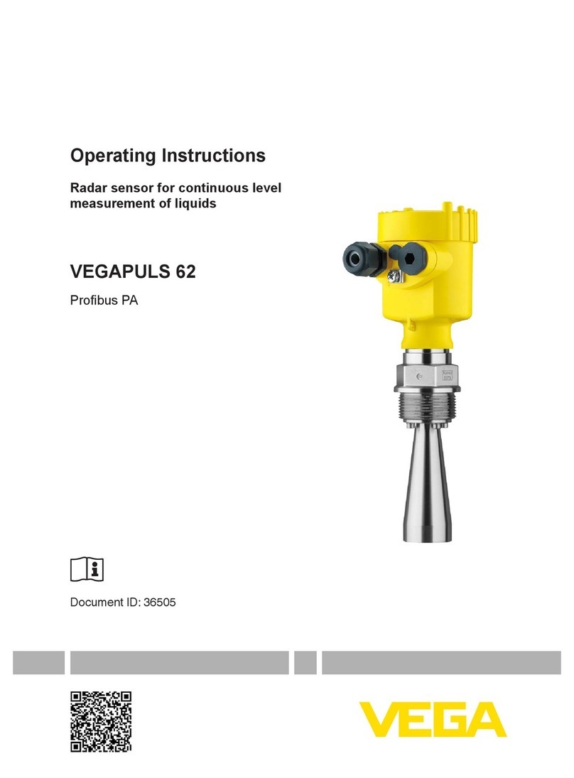
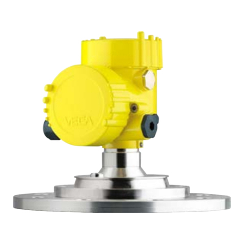
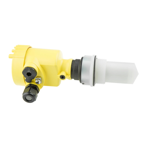
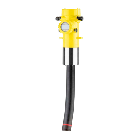
Vega VEGAPULS 62 User manual

Quick setup guide
Radar sensor for continuous level
measurement of liquids
VEGAPULS 62
HART and accumulator pack
Document ID: 47110

2
Contents
VEGAPULS 62 • HART and accumulator pack
47110-EN-140129
Contents
1 For your safety
1.1 Authorised personnel ....................................................................................................... 3
1.2 Appropriate use................................................................................................................ 3
1.3 Warning about incorrect use............................................................................................. 3
1.4 General safety instructions............................................................................................... 3
1.5 CE conformity................................................................................................................... 4
1.6 NAMUR recommendations .............................................................................................. 4
1.7 Radio license for Europe .................................................................................................. 4
1.8 Radio license for USA/Canada......................................................................................... 4
1.9 Environmental instructions ............................................................................................... 4
2 Product description
2.1 Conguration.................................................................................................................... 6
3 Mounting
3.1 Mounting preparations - Horn antenna............................................................................. 8
3.2 Mounting preparations - Parabolic antenna...................................................................... 8
3.3 Mounting instructions ....................................................................................................... 9
4 Connecting to power supply
4.1 Connection of the battery charger .................................................................................. 11
4.2 Wiring plan ..................................................................................................................... 11
5 Set up with the display and adjustment module
5.1 Insert display and adjustment module............................................................................ 13
5.2 Parameter adjustment .................................................................................................... 14
6 Supplement
6.1 Technical data ................................................................................................................ 18
Information:
This quick setup guide enables a quick setup of your instrument.
Youcanndfurtherinformationinthecorresponding,comprehensive
operating instructions. This manual is available on the supplied DVD
or in the download area under "www.vega.com".
Operating instructions VEGAPULS 62 - HART and power pack:
Document-ID 40793
Editing status of the quick setup guide: 2014-01-24

3
1 For your safety
VEGAPULS 62 • HART and accumulator pack
47110-EN-140129
1 For your safety
1.1 Authorised personnel
All operations described in this operating instructions manual must
be carried out only by trained specialist personnel authorised by the
plant operator.
During work on and with the device the required personal protective
equipment must always be worn.
1.2 Appropriate use
The VEGAPULS 62 is a sensor for continuous level measurement.
Due to the integrated accumulator the instrument is particularly
suitable as a portable measuring system or test sensor for special
applications.
Youcannddetailedinformationabouttheareaofapplicationin
chapter "Product description".
Operational reliability is ensured only if the instrument is properly
usedaccordingtothespecicationsintheoperatinginstructions
manual as well as possible supplementary instructions.
1.3 Warning about incorrect use
Inappropriate or incorrect use of the instrument can give rise to
application-specichazards,e.g.vesseloverllordamagetosystem
components through incorrect mounting or adjustment.
1.4 General safety instructions
This is a state-of-the-art instrument complying with all prevailing
regulations and guidelines. The instrument must only be operated in a
technicallyawlessandreliablecondition.Theoperatorisresponsible
for the trouble-free operation of the instrument.
Duringtheentiredurationofuse,theuserisobligedtodeterminethe
compliance of the necessary occupational safety measures with the
current valid rules and regulations and also take note of new regula-
tions.
Thesafetyinstructionsinthisoperatinginstructionsmanual,thena-
tional installation standards as well as the valid safety regulations and
accident prevention rules must be observed by the user.
Forsafetyandwarrantyreasons,anyinvasiveworkonthedevice
beyond that described in the operating instructions manual may be
carried out only by personnel authorised by the manufacturer. Arbi-
traryconversionsormodicationsareexplicitlyforbidden.
The safety approval markings and safety tips on the device must also
be observed.
Dependingontheinstrumentversion,theemittingfrequenciesarein
the C or K band range. The low emitting frequencies are far below the
internationallyapprovedlimitvalues.Whenusedcorrectly,thereisno
danger to health.

4
1 For your safety
VEGAPULS 62 • HART and accumulator pack
47110-EN-140129
1.5 CE conformity
ThedevicefulllsthelegalrequirementsoftheapplicableECguide-
lines.ByaxingtheCEmarking,weconrmsuccessfultestingofthe
product.
YoucanndtheCECerticateofConformityinthedownloadsection
of our homepage.
1.6 NAMUR recommendations
NAMUR is the automation technology user association in the process
industry in Germany. The published NAMUR recommendations are
acceptedasthestandardineldinstrumentation.
ThedevicefulllstherequirementsofthefollowingNAMURrecom-
mendations:
• NE 21 – Electromagnetic compatibility of equipment
• NE 43 – Signal level for malfunction information from measuring
transducers
• NE53–Compatibilityofelddevicesanddisplay/adjustment
components
• NE107–Self-monitoringanddiagnosisofelddevices
For further information see www.namur.de.
1.7 Radio license for Europe
The instrument is approved according to EN 302372-1/2 (2006-04)
for use in closed vessels.
1.8 Radio license for USA/Canada
The instrument is in conformity with part 15 of the FCC regulations.
Take note of the following two regulations:
• The instrument must not cause any interfering emissions
• Thedevicemustbeinsensitivetointerferingimmissions,including
those that may cause undesirable operating conditions
Modicationsnotexpresslyapprovedbythemanufacturerwillleadto
expiryoftheoperatinglicenceaccordingtoFCC/IC.
The instrument is in conformity with RSS-210 of the IC regulations.
Theinstrumentmayonlybeusedinclosedvesselsmadeofmetal,
concrete,orbre-reinforcedplastic.
1.9 Environmental instructions
Protection of the environment is one of our most important duties.
That is why we have introduced an environment management system
with the goal of continuously improving company environmental pro-
tection.Theenvironmentmanagementsystemiscertiedaccording
to DIN EN ISO 14001.
Pleasehelpusfulllthisobligationbyobservingtheenvironmental
instructions in this manual:
• Chapter "Packaging, transport and storage"

5
1 For your safety
VEGAPULS 62 • HART and accumulator pack
47110-EN-140129
• Chapter "Disposal"

6
2 Product description
VEGAPULS 62 • HART and accumulator pack
47110-EN-140129
2 Product description
2.1 Conguration
Thetypelabelcontainsthemostimportantdataforidenticationand
use of the instrument:
2
1
14
15
16
17
13
12
11
5
3
6
4
7
8
9
10
Fig. 1: Layout of the type label (example)
1 Instrument type
2 Product code
3 Approvals
4 Power supply and signal output, electronics
5 Protection rating
6 Measuring range
7 Process and ambient temperature, process pressure
8 Material, wetted parts
9 Hardware and software version
10 Order number
11 Serial number of the instrument
12 Data-Matrix-Code for Smartphone-App
13 Symbol of the device protection class
14 ID numbers, instrument documentation
15 Reminder to observe the instrument documentation
16 NotiedauthorityforCEmarking
17 Approval directive
The type label contains the serial number of the instrument. With it
youcanndthefollowinginstrumentdataonourhomepage:
• Product code (HTML)
• Delivery date (HTML)
• Order-specicinstrumentfeatures(HTML)
• Operating instructions and quick setup guide at the time of ship-
ment (PDF)
• Order-specicsensordataforanelectronicsexchange(XML)
• Testcerticate(PDF)-optional
Go to www.vega.com,"VEGATools" and "Instrument search". Enter
the serial number.
Alternatively,youcanaccessthedataviayoursmartphone:
Type label
Serial number - Instru-
ment search

7
2 Product description
VEGAPULS 62 • HART and accumulator pack
47110-EN-140129
• Download the smartphone app "VEGATools" from the "Apple App
Store" or the "GooglePlayStore"
• ScantheDataMatrixcodeonthetypelabeloftheinstrumentor
• Enter the serial number manually in the app

8
3 Mounting
VEGAPULS 62 • HART and accumulator pack
47110-EN-140129
3 Mounting
3.1 Mounting preparations - Horn antenna
The instrument is also available in versions with an antenna whose
diameterislargerthantheprocesstting(thread,ange).Insuch
casestheantennamustbedisconnectedfromtheprocesstting
before mounting. Proceed as follows:
1. Loosenthehexagonsocketscrews(3)ontheantennasocket
withanAllenwrench(size3)
2. Remove the antenna (4)
Note:
The plastic cone may not be pulled out of the antenna socket.
3. Insert the antenna from below into the vessel socket and secure it
againstfallingo
4. Retightentheantennawithhexagonscrewstotheantenna
socket;torquemax.2.5Nm(1.8lbfft)
Note:
Theradarsensorwithrinsingairconnectionorantennaextension
is provided with a notch on the antenna socket. This notch must be
alignedwiththemarkingontheprocesstting(themarkingspecies
the position of the polarisation of the radar signal).
3
4
1
2
Fig. 2: Dismounting of the horn antenna
1 Marking for the polarisation
2 Marking at the antenna socket
3 Hexagon screws on the antenna socket
4 Antenna
3.2 Mounting preparations - Parabolic antenna
The instrument is also available in versions where the antenna has
adiameterlargerthantheprocesstting(thread,ange).Withsuch
versionstheantennamustbedisconnectedfromtheprocesstting
before mounting. Proceed as follows:
1. ClampVEGAPULS62withtheange,e.g.inabenchvice

9
3 Mounting
VEGAPULS 62 • HART and accumulator pack
47110-EN-140129
2. Holdtheconnectionpiece(1)withawrenchontheatsurfaces
(widthacrossats22mm)
3. Loosen counter nut (3) completely with a wrench (width across
ats36mm)inthedirectionoftheantenna
4. Loosen compression nut (2) completely with a wrench (width
acrossats41mm)inthedirectionoftheantenna
5. Removetheparabolicantenna(4)axially
6. Mountsensorangeontheadapterangeandfastenittightly
7. Check if the O-ring seal is present on the connection piece and
make sure it is not damaged.
Note:
A damaged O-ring seal must be replaced: FKM (SHS FPM 70C3
GLT),FFKM(Kalrez6375)
8. Remount the parabolic antenna (4)
9. Fastencompressionnut(2)withawrench(widthacrossats41),
torquemax.50Nm
10. Fastencounternut(3)withawrench(widthacrossats36),
torquemax.40Nm
Note:
Ontheversionwithrinsingairconnection,makesurethattheholes
intheantennaandintheprocessttingcoincide.Thisensuresasuf-
cientairow(theairisledthroughtheholestothefeedsystem.A
rinsing of the whole parabolic antenna is not intended).
1
2
3
4
Fig. 3: Dismounting, parabolic antenna
1 Connection piece
2 Compression nut
3 Locknut
4 Parabolic antenna
3.3 Mounting instructions
1. Distancefromthevesselwall>200mm,theantennashould
protrude > 10 mm into the vessel
Mounting

10
3 Mounting
VEGAPULS 62 • HART and accumulator pack
47110-EN-140129
ca. 10 mm
> 200 mm
(7.87
")
Fig. 4: Distance of the antenna to the vessel wall/vessel ceiling
2. Note min. socket diameter depending on the socket length
For further information see chapter "Mounting".

11
4 Connecting to power supply
VEGAPULS 62 • HART and accumulator pack
47110-EN-140129
4 Connecting to power supply
4.1 Connection of the battery charger
We recommended charging the integrated accumulator completely
beforesettinguptheinstrument.Youcanndthechargingtimein
chapter "Technicaldata".
Thebatterychargerispluggedintoasocketinthesupplyroom,see
chapter "Wiring plan".
The LEDs in the supply room show the charging process and condi-
tionoftheaccumulator,seechapter"Wiring plan".
4.2 Wiring plan
2
4
3
5
0
5
1
6
2
7
3
8
4
9
modes
4 ON/OFF
3 ON/OFF 1h
1,2 OFF
Charge Accu
5..9 auto cycle
12
+
( ) (-)
1
Fig. 5: Supply room
1 Internal connection of the socket for the battery charger
2 Mode switch
3 LEDgreen,chargingprocess
4 LEDyellow,chargingstatus
5 Socket for the battery charger
The mode switch enables the selection of the following modes:
• 0=sensoro,LEDsshowtheaccumulatorstatus
• 1,2=sensoro,LEDso
• 3 = sensor on for 1 hour after pressing a key (delivery status)
• 4=sensorpermanentlyon,switchingon/oviabutton
• 5 = sensor is switched on every 30 min. for 3 min.
• 6 = sensor is switched on every hour for 3 min.
• 7 = sensor is switched on every 6 hours for 3 min.
• 8 = sensor is switched on every 12 hours for 3 min.
• 9 = sensor is switched on every 24 hours for 3 min.
ThegreenLEDcharacterizesthechargingprocess:
• LEDashes=Accumulatorischarging
• LEDlights=accumulatorisfull,batterychargershouldbe
unplugged (accumulator life time)
Supply room

12
4 Connecting to power supply
VEGAPULS 62 • HART and accumulator pack
47110-EN-140129
After pressing the key or changing the mode the yellow LED shows
theaccumulatorstatusforapproximately10sasfollows:
• LED lights = accumulator is full
• LEDashes=accumulatorshouldbecharged
• LEDo=accumulatorisempty

13
5 Set up with the display and adjustment module
VEGAPULS 62 • HART and accumulator pack
47110-EN-140129
5 Set up with the display and adjustment
module
5.1 Insert display and adjustment module
The display and adjustment module can be inserted into the sensor
andremovedagainatanytime.Youcanchooseanyoneoffourdier-
ent positions - each displaced by 90°. It is not necessary to interrupt
the power supply.
Proceed as follows:
1. Unscrew the housing cover
2. Place the display and adjustment module in the requested posi-
tion onto the electronics and turn to the right until it snaps in
3. Screw housing cover with inspection window tightly back on
Removal is carried out in reverse order.
Thedisplayandadjustmentmoduleispoweredbythesensor,anad-
ditional connection is not necessary.
Fig. 6: Installing the display and adjustment module in the electronics compart-
ment of the single chamber housing

14
5 Set up with the display and adjustment module
VEGAPULS 62 • HART and accumulator pack
47110-EN-140129
1 2
Fig. 7: Insertion of the display and adjustment module into the double chamber
housing
1 In the electronics compartment
2 Intheconnectioncompartment(withEx-d-iaversionnotpossible)
Note:
Ifyouintendtoretrottheinstrumentwithadisplayandadjustment
moduleforcontinuousmeasuredvalueindication,ahighercoverwith
an inspection glass is required.
5.2 Parameter adjustment
1. Go via the display and adjustment module to the menu "Setup".
2. In the menu item "Medium"you select the medium of your applica-
tion,forexample"Aqueous solution".
3. Select in the menu item "Application"thevessel,theapplication
andthevesselform,forexample,storagetank.
4. Carry out the adjustment in the menu items "Min. adjustment" and
"Max. adjustment".
Set parameters

15
5 Set up with the display and adjustment module
VEGAPULS 62 • HART and accumulator pack
47110-EN-140129
The radar sensor measures the distance from the sensor to the
productsurface.Forindicationofthereallevel,anallocationofthe
measured distance to the percentage height must be carried out.
100%
0%
0,5 m
(19.68
")
5 m
(196.9
")
2
1
3
Fig. 8: Parameter adjustment example min./max. adjustment
1 Min. level = max. meas. distance
2 Max. level = min. meas. distance
Forthisadjustment,thedistanceisenteredwhenthevesselisfull
andnearlyempty.Ifthesevaluesarenotknown,anadjustmentwith
otherdistances,forexample,10%and90%isalsopossible.Starting
pointforthesedistancespecicationsisalwaysthesealsurfaceof
thethreadorange.
With the function "Echocurvememory" the echo curve can be saved
at the time of setup. This is generally recommended; for using the As-
setManagementfunctionsitisabsolutelynecessary.Ifpossible,the
curve should be saved with a low level in the vessel.
WiththeadjustmentsoftwarePACTwareandthePC,thehighresolu-
tionechocurvecanbedisplayedandusedtorecognizesignal
changesovertheoperatingtime.Inaddition,theechocurveofthe
setup can be also displayed in the echo curve window and compared
with the actual echo curve.
Parameterization example
Diagnostics - Echo curve
memory

16
5 Set up with the display and adjustment module
VEGAPULS 62 • HART and accumulator pack
47110-EN-140129
Thefollowingcircumstancescauseinterferingreectionsandcan
inuencethemeasurement:
• High sockets
• Vessel installations such as struts
• Agitators
• Buildup or welded joints on vessel walls
Note:
Afalsesignalsuppressiondetects,marksandsavesthesefalsesig-
nals so that they are no longer taken into account for level measure-
ment.
This should be done with the low level so that all potential interfering
reectionscanbedetected.
Proceed as follows:
1. Select the menu item "Additional settins" with [->]andconrm
with [OK]. With [->] you have to select the menu item "False
signal suppression"andconrmwith[OK].
2. Conrmagainwith[OK].
3. Conrmagainwith[OK].
4. Conrmagainwith[OK] and enter the actual distance from the
sensor to the product surface.
5. All interfering signals in this section are detected by the sensor
andstoredafterconrmingwith[OK].
Note:
Checkthedistancetotheproductsurface,becauseifanincorrect
(toolarge)valueisentered,theexistinglevelwillbesavedasafalse
echo.Thellinglevelwouldthennolongerbedetectableinthisarea.
Ifafalsesignalsuppressionhasalreadybeencreatedinthesensor,
the following menu window appears when selecting "False signal
suppression":
Additional adjustments -
False signal suppression

17
5 Set up with the display and adjustment module
VEGAPULS 62 • HART and accumulator pack
47110-EN-140129
The menu item "Delete" is used to completely delete an already cre-
ated false signal suppression. This is useful if the saved false signal
suppression no longer matches the metrological conditions in the
vessel.
The menu item "Extend"isusedtoextendanalreadycreatedfalse
signal suppression. This is useful if a false signal suppression was
carried out with a too high level and not all false signals could be de-
tected. When selecting "Extend",thedistancetotheproductsurface
of the created false signal suppression is displayed. This value can
nowbechangedandthefalsesignalsuppressioncanbeextendedto
this range.

18
6 Supplement
VEGAPULS 62 • HART and accumulator pack
47110-EN-140129
6 Supplement
6.1 Technical data
External battery charger
Mains voltage 100 … 240 V AC
Output voltage 24 V DC
Outputcurrent(shortcircuitproof)max. 500 mA
Load current limitation 70 mA
DCplug(insideplus,outsideminus) 2.1 mm
Integrated accumulator
Type Lithium ions
Voltage 14.8 V
Accumulator capacity 4.7 Wh
Chargingperiodfrom0%to100%
approx.
4 h
Operating time after 10 min. charging of
0%
> 3 h
Operating time in mode 4 (sensor per-
manently on) with completely charged
accumulator
> 60 h
Temperature range
ƲCharge accumulator 0 … +45° C (+32 … +167 °F)
ƲAccumulator operation -20 … +60° C (-4 … +140 °F)
Temperature derating accumulator capacity
Ʋ+25° C (+77 °F) 100%
Ʋ-10° C (+14 °F) 50%

19
Notes
VEGAPULS 62 • HART and accumulator pack
47110-EN-140129

Printing date:
VEGA Grieshaber KG
Am Hohenstein 113
77761 Schiltach
Germany
47110-EN-140129
All statements concerning scope of delivery, application, practical use and operat-
ing conditions of the sensors and processing systems correspond to the information
available at the time of printing.
Subject to change without prior notice
© VEGA Grieshaber KG, Schiltach/Germany 2014
Phone +49 7836 50-0
Fax +49 7836 50-201
E-mail: [email protected]
www.vega.com
Other manuals for VEGAPULS 62
15
Table of contents
Other Vega Accessories manuals

Vega
Vega VEGAFLEX 86 User manual

Vega
Vega VEGASON 62 User manual

Vega
Vega VEGAVIB 62 User manual

Vega
Vega VEGAFLEX 82 User manual

Vega
Vega VEGAPULS 61 User manual

Vega
Vega VEGAPULS 62 User manual

Vega
Vega VEGAPULS 66 User manual

Vega
Vega VEGAPULS 66 User manual

Vega
Vega VEGABAR 82 User manual

Vega
Vega VEGAPULS 66 User manual

Vega
Vega vegacap 62 User manual

Vega
Vega POINTRAC 31 User manual

Vega
Vega VEGASON 61 User manual

Vega
Vega VEGAFLEX 62 User manual

Vega
Vega VEGASON 61 User manual

Vega
Vega VEGAVIB 62 User manual

Vega
Vega VEGAPULS 61 User manual

Vega
Vega VEGAFLEX 82 User manual

Vega
Vega VEGADIS 61 User manual

Vega
Vega VEGAPULS 11 User manual