Vehco Connect5 User manual

January 2019 Page 1 of 35
Connect5
Onboard
Installation Guide
and
System diagnostics
Version 1.6.1
IMPORTANT: PLEASE READ AND UNDERSTAND ALL THESE
INSTRUCTIONS BEFORE COMMENCING INSTALLATION.
PLEASE LEAVE THIS MANUAL WITH THE CUSTOMER FOR
FUTURE REFERENCE.

January 2019 Page 2 of 35
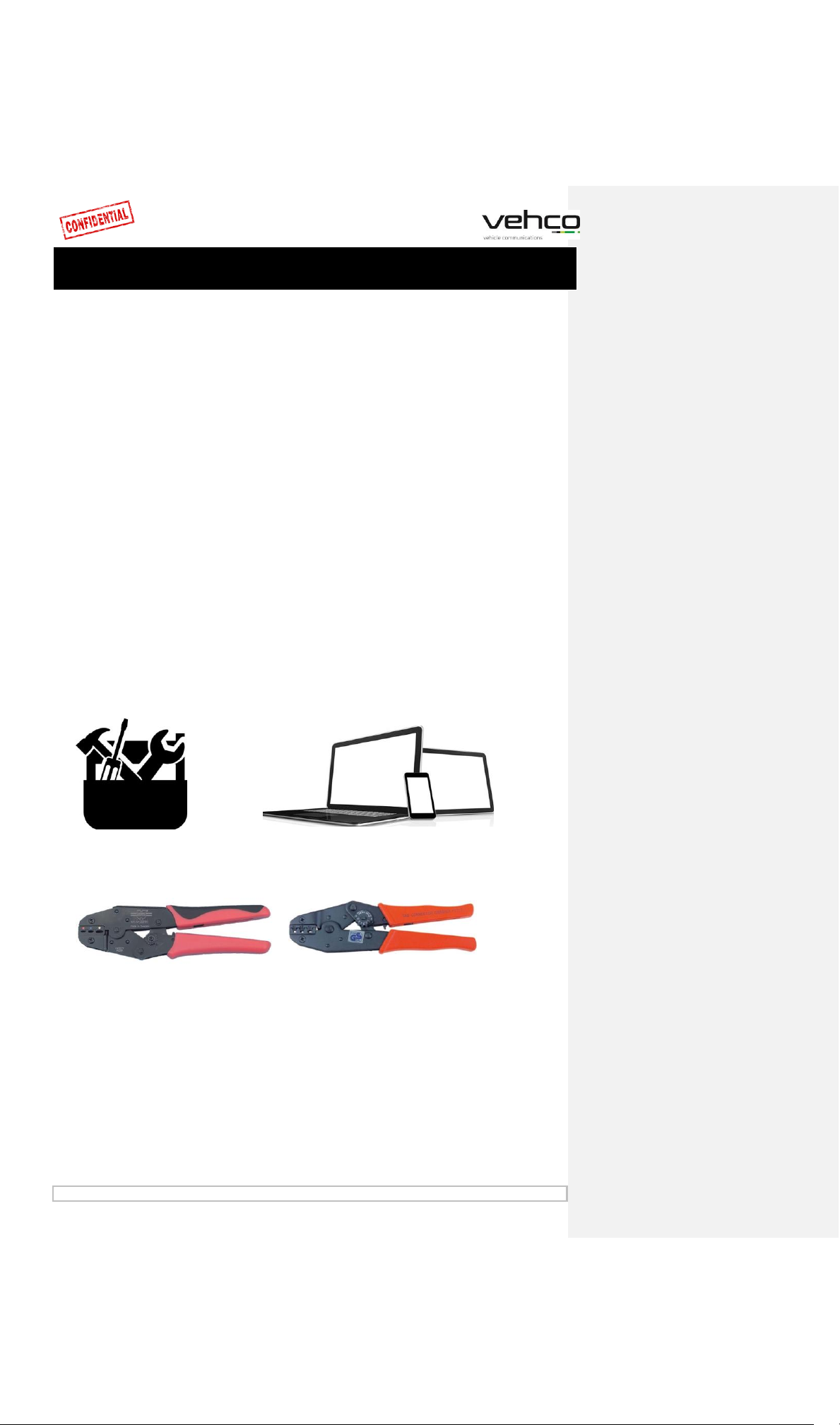
Before installation..........................................................................3
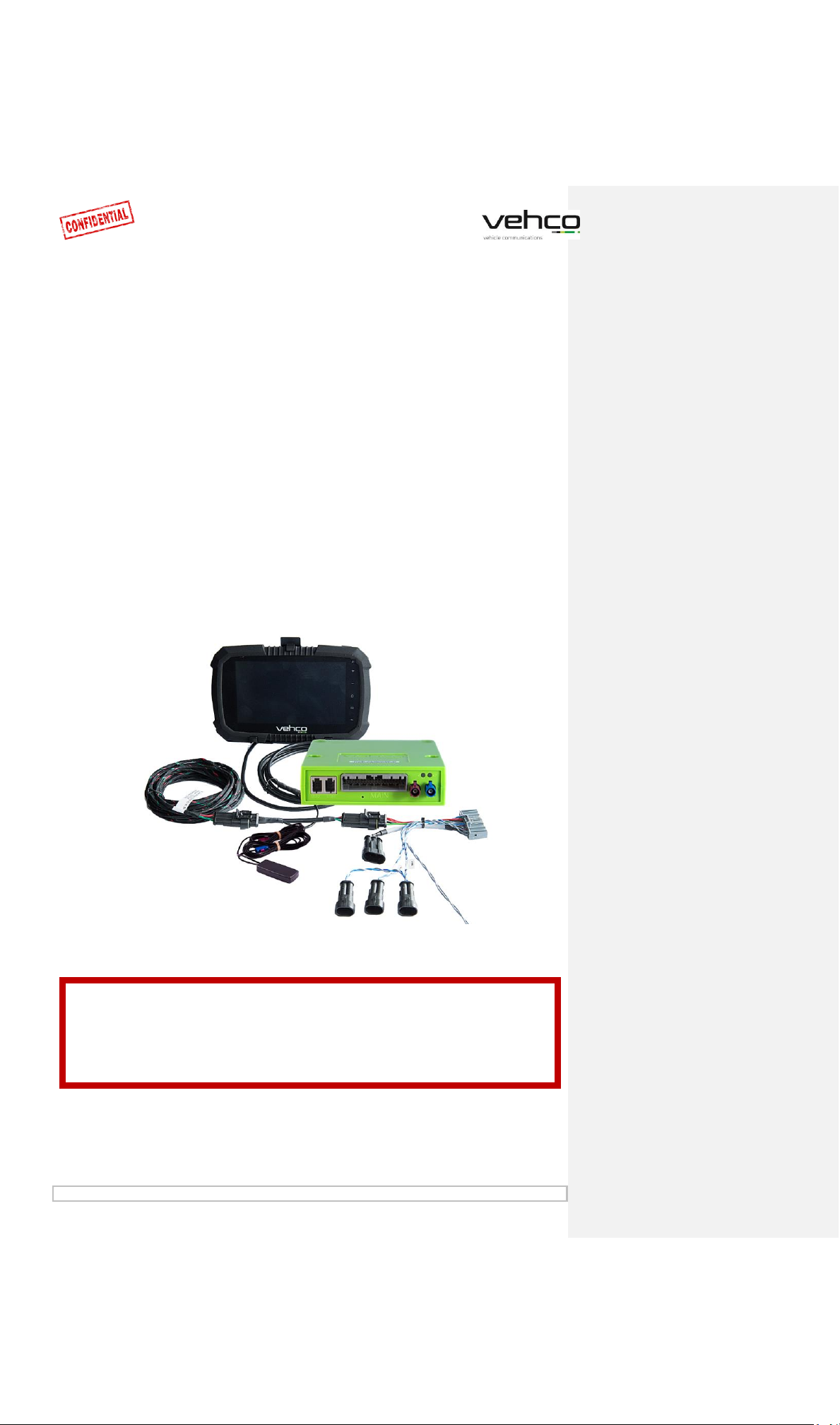
Connect5 system overview............................................................4
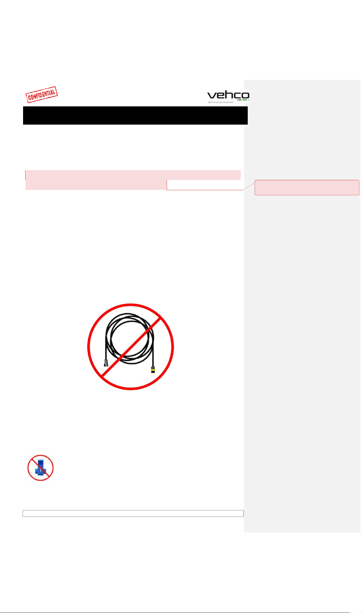
Important information...................................................................5
Step 1 –Mount Connect5 ..............................................................6
Step 2 –Main Wire Harness...........................................................7
Step 3 –GPS...................................................................................8
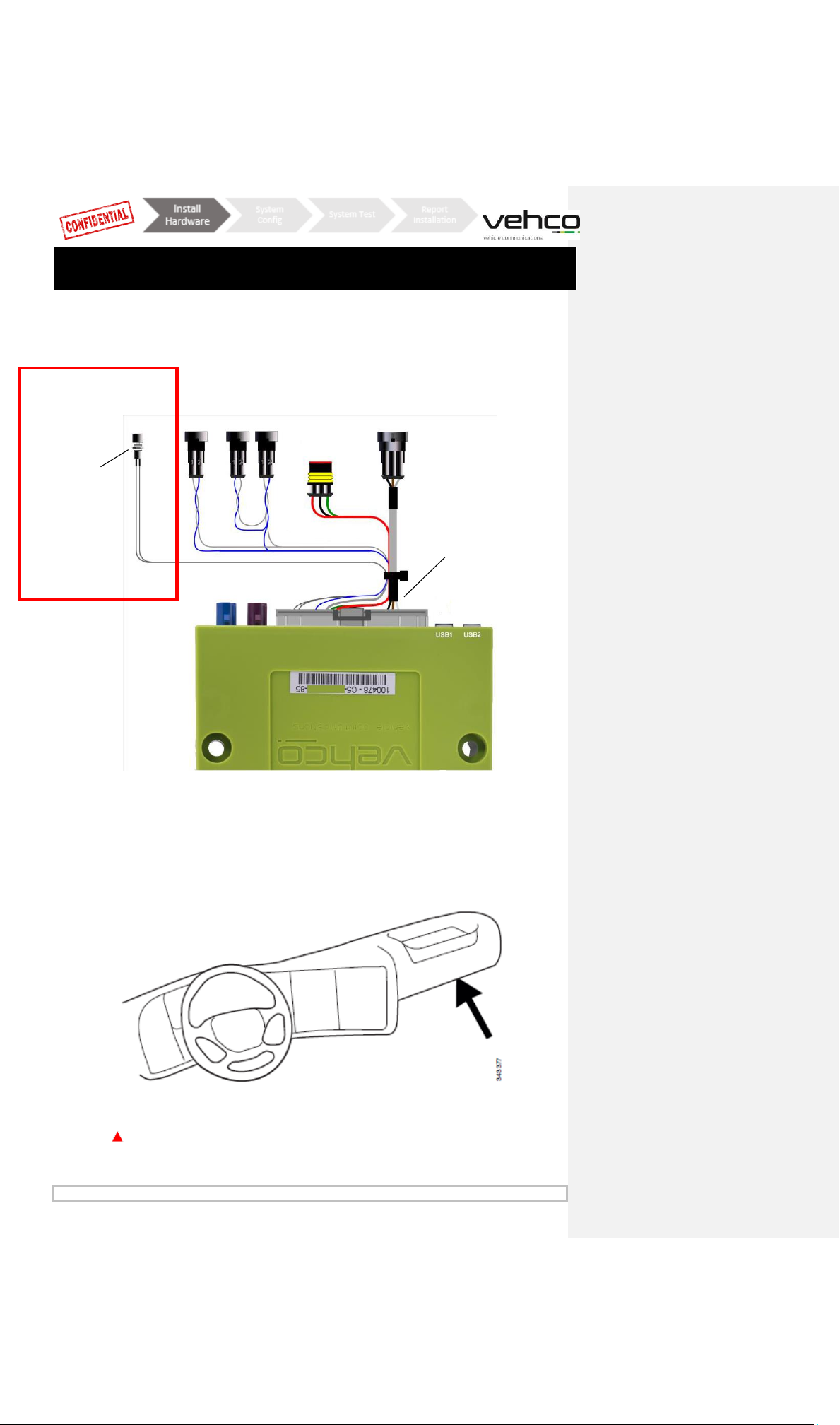
Step 4 –FMS ..................................................................................9
Step 4 –Without FMS..................................................................10
Step 5 –Tachograph ....................................................................11
Step 5 –Tachograph ....................................................................12
Step 6 –Android Screen...............................................................13
Step 7 –System Configuration.....................................................14
Step 8 - System test with screen..................................................15
Step 8 - System test without screen ............................................16
Step 9 - Installation tool...............................................................17
FMS..............................................................................................19
Truck Information ..................................................................... 20
FMS - Volvo FH/FM 2002
→
2013............................................. 21
FMS - Volvo FH4 2013
→
........................................................... 22
FMS - Volvo FM4 2014
→
.......................................................... 23
FMS - Volvo FE/FL
→
................................................................. 24
FMS - Scania P-R-T Series
→
2009-01-28.................................. 25
FMS - Scania P-R-T Series (with RTG) 2009-01-29
→
2016 ....... 26
FMS - Scania New Generation 2017
→
...................................... 27
FMS - MAN................................................................................ 28
FMS - DAF CF and XF ................................................................. 29
FMS - Mercedes Actros 2 - Bluetec 4 and 5 ............................... 30
FMS - Mercedes Actros MP4 chassis: WDB963 ......................... 31
The Connect5 system information...............................................32
Reset the Connect5......................................................................33
LED description ............................................................................34
Contact Information.....................................................................35

January 2019 Page 3 of 35
Before installation
All steps in the installation manual are mandatory otherwise the
installation will not work!
Before starting the installation, make sure you have access to the following;
1. Log in credentials to “Installer WEB” (can be provided by Customer or Vehco
Support)
oURL: http://install.codriver.com
2. Company installer code (ex.11U241B9) to “Installer WEB”
(can be provided by Customer or Vehco Support)
3. Subscription number and/or Vehicle identification in the system to be
installed (can be provided by Customer)
Pliers for insulated cable
shoe from 1.5-6.0mm
Pliers for uninsulated cable shoe
from 1.5-6.0mm (roll pressing)
Tools to disassemble the
dashboard
Device: computer, tablet or phone
with access to internet

January 2019 Page 4 of 35
Connect5 system overview
100479
Reset button
FMS CAN
FMS
Direct CAN
Monitor cable
100505
100503
Digital Tachograph
100482
100450
Connect5 Road box Id
number
100502
100497

January 2019 Page 5 of 35
Important information
The regulations set by the truck manufacturer must always be
followed.
One 3A fuse must always be mounted as close to the supply
connector as possible. See page 4, 9 or 10.
All cables must be mounted so that they can’t be pinched. The
cable isolation must not be damaged.
All cables coming out of the Connect5 box must be zip-tied to
something nearby (max 20cm), this to minimize oscillation in
the connector.
All extension cables must be cut to length, do NOT wind up
excessive cables in spools.
It is important that the Connect5 box is well fixed to avoid
vibrations!
High reliability and trouble-free performance of the system is
achieved only by high quality installation. Do not make any
cable by-pass connections.
Kommenterad [TA1]: Should this paragraph be
removed? It is not found in the Swedish version of the
manual.

January 2019 Page 6 of 35
Step 1 – Mount Connect5
Write down the Connect5 box serial number that begins with “C5-XXX“(can be
found on the box).
The “Connect5 box 100765” unit is typically mounted under the dashboard in the
vehicle, near the fuse panel.
It is important that the Connect5 box is well fixed to avoid vibrations!
100765

January 2019 Page 7 of 35
Step 2 – Reset button
Put the “Main Wire Harness 100482” in the Connect5 box and mount the reset
button from the main wire harness near or in the fuse panel.
100482
it needs to be accessible by the driver without the need of tools.
Reset button

January 2019 Page 8 of 35
Step 3 – GPS
The internal “GPS/GSM combi antenna 100479” should be placed somewhere on
top of the dashboard near the windshield (with the text “GPS” facing the sky).
The antenna cables should not be routed near the speakers or the CB radio (Citizens
Band Radio) as well as the CB radio antenna wire.
If the truck is equipped with a MAUT antenna, the GPS/GSM combi antenna must
not be placed closer than 30 cm to the MAUT antenna
100479

January 2019 Page 9 of 35
Step 4 – FMS
First check if the truck has the FMS connector or not. If the vehicle is equipped with
the FMS connector, transmission is not always activated. If no transmission, the
truck must go to its brands workshop to activate the FMS function.
Read chapter FMS to see information about FMS connector for a specific vehicle
modell.
Mixing up “Direct CAN” and
“FMS” connections, can lead
to malfunction of the vehicle
under certain conditions.
FMS
Mount the “FMS CAN cable 100503”and “Power cable 100502”in the included “FMS
connector 100450”and connect that to the corresponding FMS connector in the vehicle.
Pin 1 Black (ground)
Pin 10 Green (ignition)
Pin 6 Blue (CAN High)
Pin 12 Red (Battery)
Pin 9 Grey (CAN Low)
100497
100502
100503
100450
100505
FMS CAN
Reset button
Digital Tachograph
Direct CAN
100482
Connect5 Road box ID

January 2019 Page 10 of 35
Step 4 – Without FMS
First check if the truck have the FMS connector or not. If the vehicle is equipped
with the FMS connector, transmission is not always activated. If no transmission,
the truck must go to its brands workshop to activate the FMS function.
Read chapter FMS to see information about FMS connector for a specific vehicle
modell.
Mixing up “Direct CAN” and
“FMS” connections, can lead
to malfunction of the vehicle
under certain conditions.
Direct CAN
FMS CAN
Without FMS
If the vehicle doesn’t have the FMS connector, read Step 5-how to connect C5 & C7 in the
tachograph(cable 100503).
If the vehicle doesn’t have the FMS connector, mount the power cable (cable 100502) in
the fuse panel as below.
Red cable 12-24 v
Green cable ignition
Black cable ground
100502
100497
100482
Connect5 Road box ID
100503
Reset button
Digital Tachograph

January 2019 Page 11 of 35
Mount a secondary “CAN BUS cable 100503”
(only if you don’t get any Tacho CAN connection from the FMS connector, or when
direct CAN option is used)
Blue wire Connector CPin 5 CAN High
Grey wire Connector CPin 7 CAN Low
•IF C-CAN on tachograph is not connected to the FMS-gateway or when using
the direct CAN option:
1. A termination loop in-between C7 and C8 should be in place. IF not, one needs
to be made -this will terminate the tachograph with 120Ω.
2. Combined resistance between CAN High and Low should be 60Ω when
everything is connected.
Step 5 – Tachograph
Route the “D8 cable 100505” from the Connect5 box via the A-piller to the
tachograph and connect the brown cable in connector D on pin 8.
Mixing up “Direct CAN” and
“FMS” connections, can lead to
malfunction of the vehicle under
certain conditions.
100505
Digital Tachograph
100503
Gray wire from
100503
Direct CAN
FMS CAN

January 2019 Page 12 of 35
Step 5 – Tachograph
Always provide a tachograph connection as described on previous pages.
Important:It is REQUIRED to establish both cable connection between the
Connect5 unit and the digital tachograph.
The CAN connection alone is NOT sufficient to get full functionality.
Important:If the tachograph is sealed with a shield above the connectors, it
must be removed by an authorised tachograph technician.

January 2019 Page 13 of 35
Step 6 – Android Screen
The fixed Android screen is optional, an installation can take part without the
screen. If an Android screen should be mounted, follow instructions below.
Mount the android screen where the customer has given their approval.
Fasten the screen using the two screws on the backside of the screen and connect
the monitor cables in USB1 on the Connect5 box and the other part of the cable
between incoming power and “Main cable 100482”.
Screen cable are not allowed to be cut and must not be wound in a spool!
USB1

January 2019 Page 14 of 35
Step 7 – System Configuration
Installer WEB (STORK) –installation configuration
•On your computer/tablet/phone
open: http://install.codriver.com
•Log in with your credentials
•Enter the Company installer code
Configuration
1. From the list, press on the appropriate subscription/vehicle (if you don’t
know which subcription (SUB-xxxxx) that should be used, please contact the
office).
2. Change Road box Id (begins with C5-XXX) to match the Connect5 box and if
needed, add Reg nr and Internal nr.
3. Press ”Save”
When the hardware is installed, turn on the ignition to do System Configuration.
Onboard Notifier
During the software download and installation process the screen will display
the window shown below.
Note that if this is not displayed it could be that USB connection is missing,
verify connection and that you can see the two icons in the top left corner of
the screen.
USB connection

January 2019 Page 15 of 35
Step 8 - System test with screen
Before using the Connect5 system, a final diagnostic test shall be made.
By doing this, you’ve made sure everything is in order before leaving the vehicle.
With screen:
In the Vehco application, sign in using the Service account
Username: 0000
Password: 13579
1. From the Start menu, with ignition ON, click the Diagnostics button (If you
don’t find the button on the first page when clicking Start menu, swipe left).
2. Start the test by clicking ”Run Test”. During the test, the “Run Test” will
change to “Testing”
The test can take up to 5 minutes
Turn off the ignition and verify that the vehicle icon (on the right side of the
screen) switches from green to a yellow triangle.
If test finishes with any errors, check installation and call your local Vehco
Support.

January 2019 Page 16 of 35
Before using the Connect5 system, a final diagnostic test shall be made.
By doing this, you’ve made sure everything is in order before leaving the vehicle.
•From your phone/tablet/computer open:
http://install.codriver.com
•Log in with your credentials
•Enter the Company “installer code”
Make sure that the ignition is on before doing
the test.
1. From the list, press on the
appropriate subscription/vehicle.
2. Press the button
to run diagnostic on the installation.
3. The diagnose may take up to a few minutes to
complete, press to update.
Check the result to see if the installation is done
properly.
The test can take up to 5 minutes
If test finishes with any errors, check installation and call your local Vehco
Support.
Step 8 - System test without screen

January 2019 Page 17 of 35
Step 9 - Installation tool
The installation form is used to send in the installation information.
•Visit on your phone/tablet/computer:
http://install.codriver.com
•Log in with your credentials
•Enter the Company “installer code”
1. From the list, press on the
appropriate subscription/vehicle to enter
the installation form.
2. Fill out the installation form and press
”send” to submit.

January 2019 Page 18 of 35
Reference information
The following pages contains detailed information regarding the
installation procedure.

January 2019 Page 19 of 35
FMS
ATTENTION
FMS vs. Direct CAN
•The spider cable is equipped with 2alternative connections for vehicle data:
FMS and Direct CAN.
Direct CAN is only used in special cases and requires a special cable provided
seperatly by Vehco upon request.
NOTE! It is very important to use the Direct CAN cable only in conjunction with
the direct CAN Connector of the Spider cable.
Mixing up “Direct CAN” and “FMS” connections, can lead to malfunction of the
vehicle under certain conditions.
If the vehicle is NOT equipped with FMS (illustrated on the upcoming pages)
please contact your local Vehco Support, see contact info on the last page of this
document.
Direct CAN
FMS CAN

January 2019 Page 20 of 35
Truck Information
•On the following pages, you’ll find descriptions of body builder information and
FMS interface options.
•Body builder information and FMS connection options are based on
data/information provided by the different truck manufacturers.
Vehco takes no responsibility for the information/data provided by the truck
manufacturers.
Table of contents