Veichi Electric AC70E-S2-R40G User manual

1
FOREWORD
Thank you for using AC70E series inverter produced by Veichi Electric Co.Ltd
AC70E series inverter is a new generation of high performance mini frequency inverter independently
developed by Veichi, With advanced control method and rich function design. Users will be satisfied by
the simplified PLC, PID adjustor, programming I/O terminal, RS485 interface, analog I/O terminal, and
other specific control functions for particular industries in the benefit of AC70E
This manual is the supporting data sheet for AC70E
This instruction manual includes save tips, instructions (messages) of installing wiring, keyboard
operation, simple function table, troubleshooting, maintenance only. For parameters setting detail, pls
read AC70 general used series manual or consult us. For the best results and safe operations with the
AC70 series, carefully read and keep this manual. Make sure it is handy for the ultimate user of the
inverters for reference.
To receive technical support related to the inverter, please contact the Veichi sales office or the dealer
from whom you purchased. You can also contact our Customer Service Center, and we will try our
best to help you.
We are sparing no effort to upgrade our products and regret not to issue prior notification if there is any
revision to this instruction manual. Pray for your consideration for the inconveniences

2
Chapter 1: Summarize
1.1 Safety requirements and cautions
To ensure safety of your health, equipment and property, please read this chapter carefully before use
the frequency inverter and act in compliance with the instructions while carrying, installing, debugging,
running and overhauling the frequency inverter.
Warn sign and meaning
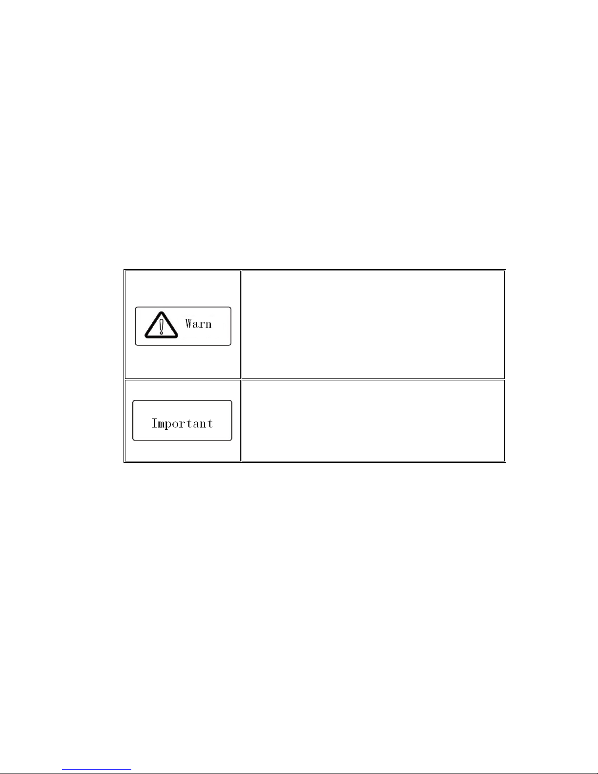
Danger: it ill cause danger of serious injuries and even death hile
operating against the rules
Caution: it ill cause danger of light injuries or equipment
destruction hile operating against the rules
Qualified operation
Only qualified person after professional train can operate the equipment.The operator must be with
professional train, familiar with installation, wiring, running and maintain of equipment, and can deal
emergency case.
Safe guide
Warn sign is for safe, to prevent operator from hurt and prevent this product and relating equipment
from being damaged. Before operating, be sure to carefully read the manual about safety, installation,
operation and maintenance and obey to the safe rules and warn sign.
●
Right transport, store, installation and careful operation and maintenance is most important for inverter safe run. In
transport and store process, make sure the inverter is free from impact and vibration. It must be stored where is dry,
without corrosive air and conductive dust, temperature lower than 60 .
℃
●
This product carries dangerous voltage and controls driver machine with potential danger. If not abide the
regulations or requirements in this manual, there is danger of body injury even death and machine system damage.
●
Do not wire while the power is conneted. Otherwise there is danger of death for electric shock. Before wiring,
inspection, maintenance, please cut power supply of all related equipments and ensure mains DC voltage in safe
range. And please do operation after 5 mins.
●
Power wire, motor wire and control wire should be all connected firmly. Earth must be reliable and earth resistance
must be lower than 10Ω.
●
Human body electrostatic will seriously damage inner sensitive components. Before operation, please follow ESD
measures. Otherwise there is danger of iverter damage.
●
Inverter output voltage is pulse wave. If components such as capacitor what improves power factor and
pressure sensitive resistance for anti thunder and so on are installed at the output side, please dismantle or change
to input side.
●
No switch components such as breaker and contactor at the output side. (If there must be one, please make sure
the output current is 0 while the switch acting).
●
No matter where the fault is, there is danger of serious accident, even human body injury what means dangerous
malfunction possibility. So there must be additional external prevent measures or other safety devices, such as
independent current limiting switch, machinery fense and so on.
●
Only used in application fields as maker stated. No use in equipments related to special fields such as emergency,
succor, ship, medical treatment, avigation, nuclear and etc.
●
Only service department of the maker or its authorized service center or professional person trained and authorized

3
by Veich can maintain the products. They should be very familiar with the safety warning and operation gist in this
manual.
1.2 Before use
Pls check whether any package damage while receiving the product you ordered. If the package is ok, pls open it and check the
inverter. If damage caused in transport, it is not duty of Veich company. But please contact Veich or the transport company
immediately.
After checking the product, please also check if the model is the one you ordered. The model of the product is on the
nameplate “MODEL” column. If any problem, please contact us freely.
Nameplate position and content
Model explaination
Single phase 220V Three phase 380V

4
Model Max motor
Ratted
current
Model Max motor
Ratted
current
AC70E S2 R40G 0.4kW 2.5A AC70E T3 R75G 0.75kW 2.3A
AC70E S2 R75G 0.75kW 4A AC70E T3 1R5G 1.5kW 3.7A
AC70E S2 1R5G 1.5kW 7A AC70E T3 2R2G 2.2kW 5A
AC70E S2 2R2G 2.2kW 10A AC70E T3 3R7G 3.7kW 8.5A
1.3
Product technique specifications
Items Specifications
Power Voltage/frequency
Single phase 220V 50/60Hz
Three phase380V 50/60Hz
Allowable fluctuations voltage:±15%, frequency:±5%
Control
Frequency range 0 400Hz
Frequency ACCuracy ±0.5% of max frequency
Frequency setting
resolution
0.01Hz:Operating“up”and”down”keys on keyboard
0.2Hz:Potentiometers analog input
V
oltage/frequency
characteristics
Voltage 50%
100% the rated voltage adjustable,
Motor rated frequency 25 400Hz(2000Hz) adjustable
Carrier frequency 1.0 15.0KHz/Random carrier modulation
Torque upgrade
0
25
.
0% adjustable
/
auto torque upgrade
/
random V/
F curve
optional
Maximum Capacity 150% for one minute, 180% for 2s, 200% instant jump.
ACC and DECtime 0.1 6500s
Rated output voltage
Take advantage of the power supply voltage compensation
function, if motor rated voltage is 100%,the voltage can be set in
the 50 100% scope(the voltage output should not exceed the
input voltage )
AVR adjust When the grid voltage fluctuates, changes in the output voltage is
very small, remained constant V / F
Automatic
energy saving
operation
ACCording to the load conditions, automatic optimize the V / F
curves to implement energy saving operation
Standard functions
PID control,
ACC
and
DEC
time adjustable,
ACC
and
DEC
mode
variable, Carrier frequency adjustment, Torque upgrade, Current
limiting, Speed tracking and restart, Frequency hopping,
Frequency fluctuation limite control, Program running, Multi steps
speed, Pendulum frequency operation, RS485, Analog output,
Pulse output frequency
Brake Energy consuming braking, DC braking
Frequency setting input
Key
board number settings, keyboard potentiometers
/
external
terminal VS: 0 ~ 10V, the external terminal AS : 4 20mA, RS485
and signal composition and terminal options
Signal Feedback input
External terminal VS: 0 ~ 10V external terminal AS: 4
20mA,
RS485
Input order signals
Start, stop, positive and negative rotating , jog, multi
steps speed,
free parking, reset, ACC and DECtime choice, frequency settings
channels choice, external malfunctions alarm

5
External output signal
Relay output, the collector outp
ut, 0
10V output, 4
20mA output,
the frequency pulse output
Protection function
Overvoltage, undervoltage, current limiting, over
current,
overload, electric thermal relays, overheat, pressure stall, data
protection
Display
Setting Function number/data
Running
Output frequency, give frequency, output current, input voltage,
output voltage, motor speed, PID feedback, quantitative PID,
module temperature, input and output terminal
Fault
Overvoltage, undervoltage, overcurrent, short circuit, phase
missing, overload, heat, pressure stall, current limiting, data
protection is damaged, current fault operating conditions,
historical fault
Condition
Installation sites
Indoor, elevation of not more than 1000 m, no corrosive gases
and direct sunlight
Temperature, humidity 10—+40
℃
, 20%—90%RH(No condensation)
Vibration Below 20Hz less than 0.5g
Storage Temperature 25—+65
℃
Installation mode Wall mounted mode
Protection degree IP20
Cooling Mode Forced air cooling
1.4 Cautions in utilization
Frequency inverter is designed to be permit to run under industrial surrounding with electromagnetic
interference. Usually, if install quality is good, it ensures frequency inverter safe run without fault. Pls
install according to below rules to ensure reliable run and avoid the impact of electromagnetic
interference.
● Ensure all equipments connected to frequency inverter are connected to star earth or common
earth bus by short and thick cable as well as frequency inverter. Motor earthing should be as
close as possible. Do not connect motor cruster to earth terminal of frequency inverter or
protection earth of control system.
● Conductor should be flat/ multi cores what has lower impedance at high frequency.
● Cut cable neatly to ensure unshield cable as short as possible.
● Control wire should be away from the supply cable and motor cable as far as possible and use
independent wire slot. While it must across to the supply cable and motor cable, should be 90º
vertical acorss.
●Ensure that the contactor in the cabinet has wave surge suppresser.Or‘R C’damping circuit is
connected to the winding of AC contactor. Voltage dependent resistor corresponding to the
winding voltage is used. And freewheel diode or components such as voltage dependent
resistor corresponding to the winding voltage are connected to DC contactor. It is very important
while contactor, controlled by output relay of inverter, acts frequently.
● Cable connected to motor should be shielded cable or armoured cable. The two barriers are
earthed reliably by cable grounding card.
● Build noise filter at the input side to reduce electromagnetic interference from other equipments
at the power grid side. The noise filter should be as close to the inverter power input terminal as

6
possible. Meantime, the filter must earth reliably as the inverter.
● Build noise filter at the output side to reduce radio interference and inductive disturbance. The
noise filter must be as close to the inverter output terminal as possible. Meantime, the filter must
earth reliably as the inverter.
● Anytime, control circuit wire should be shielded cable.
● Add zero phase reactor in power supply wire near inverter input terminal and add zero phase
reactor in the motor wire near inverter output terminal to reduce electromagnetic interference to
the inverter efficiently.
● Earthing
Right and reliable earthing is the basic condition of safe and reliable running of the product. For
right earthing, please read the following notice carefully.
● In order to avoid electric shock, earthing cable should be the
size as electric equipment technic standard required and
cable length should be as short as possible. Otherwise
inverter leakage current will causes unstable potential of
the earthing terminal which is far from the earthing point.
Electric shock accident will happen frequently.
● Earth terminal must earth. Earth resistance must be below
10Ω. Otherwise there is danger of death.
● Please do not share earth cable with welder or other big
current/pulse power equipment. Otherwise inverter will act
abnormally.
● While multi inverters are using at the same time, please do
not wind the earth wire to loop type. Otherwise inverter will
act abnormally.

7
Chapter 2: Installation
2.1 Inverter stable running environment
Install environment is very important to the best use of this product for long time. Pls install this product
in the enviorment as the folling chart requirement.
Environment
Requirement
Install place
Indoor without direct sunshine
Install temperature
10
~
+40
℃(
hanging type
)
10
~
+45
℃(
cabinet type
)
Store temperature
20
~
+60
℃
Humidity
<95%RH, no condensation
Surrounding
Please install the inverter in place as below
:
● Place without oil mist
、
corrosive gases
、
flammable gases
、
fust or etc.
● Place without metal dust
、
oil
、
water or etc into inverter (please do not install
inverter on flammable material such as food and etc).
● Place without radioactive material or flammablematerial.
● Place without poisonous gases or liquid.
● Place with very little salification erosion.
● Place whihout direct sunshine.
Altitude
<1000m
Vibration <10
~
20Hz
∶
9.8m/s
2
<20
~
55Hz
∶
5.9m/s
2
Installation and
cooling
● Inverter can not be installed horizontally, must be installed vertically.
● Please independently install high heating equipments such as braking resistor
and etc which can not be installed in the same cabinet with inverter, stalled at
the air in port of the inverter is strictly prohibited.
2.2 Installation notice and related requirement
● AC70E inverter components

8
● Installation direction and space
Single machine installation: to ensure enough ventilation and wiring space for inverter cooling, please
follow installation conditions as below.It should adopts hanging style or closet style with upright
installation and keeps enough space with surroundings or the wall.
Multi inverters paratactic installation: while install multi inverters in cabinet, please ensure installation
space as below.

9
2.3 Dimension of inverter and keyboard
W1
H
1
W
H
D
D1
MODEL WW W1 H H1 D D1
INSTALLATION
APERTURE
AC
70E
S2
R40G
88 75 142.5
129.5
142 132 ф5
AC
70E
S2
R75G
AC
70E
S2
1R5G
AC
70E
T3
R75G
AC
70E
T3
1R5G
AC
70E
S2
2R2G
106
90
172
158
142
132
ф6

10
AC
70E
T3
2R2G
AC
70E
T3
3R7G
2.4 Keyboard dimension (unit: mm)
58
7
0
16.5
20.9
4
5
37
1
8
.
5
6
7
.
8
58
2.5 Electric installation
This chapter explains the regulations that users have to obey aimed to ensuring safe use, best
performance and reliable running.
Note:Analog monitor output is special output of meters such as frequcy meter, current meter, voltage
meter and etc. It can not be used for control operations such as feedback control.
●Switch terminals connection function specification
Switch terminal
Selectable
position
Picture example Function specification

11
J1 0.2 10kHz frequency output
J2 0 20mA current output
4 20mA current output
J3 0 10V voltage output
● Suggested braking resistance
Single phase 220V Single phase 220V
Motor
power
Resistance
value
Resistance
power
Braking
moment
Motor
power
Re
sistance
value
Resistance
power
Braking
moment
0.4 kW 400Ω 100W 100%
0
.
75
kW 750Ω 150W 100%
0.75 kW
200Ω 120W 100%
1
.
5
kW 400Ω 300W 100%
1.5 kW 100Ω 300W 100%
2
.
2
kW 250Ω 400W 100%
2.2 kW 75Ω 300W 100%
3
.
7
kW 150Ω 500W 100%
● Main circuit terminals
Terminal Name Function definition
(+) Braking resistance
terminal Used for external braking resistance to realize quick stop.
PB
R/L
AC input terminal Used to connect AC power supply (R/L,S,T/N for T3 AC
input:R/L,T/N for S2AC input).
S
T/N
U
AC output terminal Used to connect the motor or other sensitive/resistive load.
V
W
Earth Earth terminal, earth resistance<10 OHM
● Control loop terminals

12
Terminal Name Function definition
TA Normally open
contact
Can set the action and object by programme.
Max contact capacity: 3A/240VAC
TC
Y Collector
open output
Can set the action and object by programme.
Max contact capacity:DC30V/50mA
+24V Auxiliary
power output + Max output: 24VDC/100mA
。
COM Auxiliary
power output
FWD Forward Short connect with (COM) valid.
REV Reverse Short connect with (COM) valid.
X1
Multi function conta
ct
input
X1
Short connect with (COM) valid.
Multi function input terminals can be programme set definition. Pls
refer F 01 F 04
。
X2
Multi function contact
input
X2
X3
Multi function contact
input X3
X4
Multi function contact
input
X4
AO Analog output
Physical type of output signal
:
0
10V
0
20mA 4
2
0mA
frequency pulse output, selectable by function F 61/F 62 or switch
J1 J2 J3.
AS Current analog input As inverter control signal or feedback signal, can set the act range
and response speed by programme.
VS resistance
:
89KΩ, AS resistance
:
250Ω.
VS Voltage analog input
+10V Signal auxiliary
power terminal Max output 10VDC/50mA
。
GND Signal auxiliary
power terminal Common auxiliary power of analog output, analog input signal.
A+
Communication
terminal A+
RS485 communication port
B Communication
terminal B

13
Chapter 3: Keyboard and Operation
3.1
Keyboard layout and function specification
Key Key name Key functions
Menu key
Enter menu while standby or running.Press this key to return while
modify parameter. While standby or running, press for 1 sec to enter
monitorning interface.
Confirm/modif
ykey
Press to modify parameter while in menu interface.Press again to
confirm aftr modify. While standby or running, press to change LED
monitoring items at stop
Up/down key
Select parameter group in menu interface. Modify parameter while in
modify interface. Modify given frequency or PID or given torque while at
standby or monitoring state
(
While given frequency or PID or given
torque are set by keyboard
)
Shift key
Select digit of function no modified by up/down key
;
Select parameter
digits modified by up/dowm key. Change LED monitoring items while
standby or running
Forward key While run/stop is controlled by keyboard, press this key, the inverter
forward rotate.
Jog/Reverse
key
While run/stop is controlled by keyboard, press it, machine will reverse
if this key is defined as REVERSE and machine will jog if this key is
defined as JOG.
Stop/Reset
key
Machine stops if press it while run/stop is controlled by keyboard. Its
efficiency range is defined via function no F 07. Inverter reset if press it
in fault state(no reset if fault is not solved)
Potentiometer
key
Can be used to adjust given frequency while it set as potentiometer
adjust speed.

14
3.2
Indicating lamp meaning specification
Name State Meaning
Unit
indicators
Hz Flashing display value is given frequency.
Hz On display value is output frequency.
A On display value is output current actual value.
V On display value is input voltage.
V Flashing display value is output voltage.
RPM On When "Hz" indicator and the "A" indicator light at the same
time, display value is the motor speed.
% Flashing When the "A" indicator and the "V" indicator flashing at the
same time, display value is gived PID value.
% On When the "A" indicator and the "V" indicator light at the
same time, display value is the amount of PID feedback.
stateindic
ators
FWD On Frequency inverter turns forward.
FWD Flashing Frequency inverter reverses.
FWD Off Frequency inverter is close down
Function
indicators
REV/JOG On This key is defined as the jog function key.

15
Chapter 4: Functional Parameter Table
Here only simple parameter table. For details, pls read AC70 series manual or consult us.
“●”:Means that the parameter can be revised during frequency inverter in a running state.
“
〇
”:Means that the parameter can not be revised during frequency inverter in a running state.
“×”:Means that the parameters can only be read and can not be changed.
“–”:Means that the parameter is only set by the manufacturer.
“
※
”:Means that the parameter is related to the type of the frequency inverter
4.1 Basic parameter
Code
funcion
Fucntion name Setting range and definition Factary
default
pr
op
ert
y
Refer
to
page
Comm
unicati
on
code
E 00 Control method selection
0: Open loop vector control without
PG
1: V/F control mode
1
〇
69 100H
E 01 Running control command
chanel selection
0:
Operator keypad
1: External terminal control
2: RS485 Communications port
control
0
〇
69 101H
E 02 Frequency reference given
main channel selection
0: Operator keypad digital given
1: Potentiometer of keypad
2: Terminal VS1 analog voltage 0 10V
3: Terminal AS analog current signal
4
~
20mA
4: Terminal VS2 analog voltage 10
~
10V
5: Pulse train signal
6: RS485 communication port
7: Up and Down control
8: General PID operation
9: Constant pressure PID control
10: Program running
11: Swing frequency run
12: Terminal selection:
1
〇
69 102H

16
E 03 Frequency reference given
auxiliary channel selection
0: Operator keypad digital
1: Potentiometer of keypad
2: Terminal VS1 analog voltage
0 10V
3: Terminal AS analog current signal
4
~
20mA
4: Terminal VS2 analog voltage 10
~
10V
5: Pulse train signal
6: RS485 communication port
7: Up and Down control
8: General PID operation
9: Constant pressure PID control
10: Program running
0
〇
71 103H
E 04 Frequency reference given
channel gain
0.01
~
5.00 1.00
〇
72 104H
E 05 Frequency reference given
channel combination mode
0: Main channel is valid, auxiliary
channel is invalid.
1: Auxiliary channel valid
,
main
channel invalid
2: Both channel is valid if non zero
value, main channel priority
3: Main channel + K×auxiliary
channel
)
4: main channel
(
K×auxiliary
channel
)
5: MAX [main channel , (K×auxiliary
channel)]
6: MIN [main channel , (K×auxiliary
channel)]
7: Auxiliary channel + (K×main
channel)
8: Auxiliary channel (K×main
channel)
9: MAX [(K×main channel), auxiliary
channel]
10: MIN [(K×main channel), auxiliary
channel]
0
〇
72 105H
E 06 Upper LED monitor selection
0: Frequency Given
1: Output frequency
2: Output current
3: Input voltage
4: Output voltage
5: Machine speed
6: PID given given
7: PID feedback value
0
●
72 106H
E 07 Lower LED monitor selection 1
●
72 107H
E 08
REV/JOG key of keypad
function selection
0: Reverse
1: Jog 0
●
73 108H
E 09 Maximum frequency 0.01
~
600.00Hz 50.00Hz
〇
73 109H
E 10 Upper limit frequency lower limit frequency
~
maximum
frequency 50.00Hz
●
73 10AH

17
E 11 Lower limit frequency 0.00
~
Upper limit frequency 0.00Hz
●
73 10BH
E 12
Lower limit frequency r
unning
mode
0: Stop
1: running with lower limit freqeuncy 1
●
73 10CH
E 13 Acceleration time 1
0.1
~
6500.0s
※
●
74 10DH
E 14 Deceleration time 1
0.1
~
6500.0s
※
●
74 10EH
E 15 Acceleration /deceleration
mode selection
LED unit digit: decelerate
/decelerate mode.
0: linear accelerate
1: S curve
LED tens digit:
Accelerate/decelerate time datum
point.
0: Motor rated frequency
1: Maximum frequency
LED hundreds digit:
Equidistance stop function
0: Disable
1: Enable
LED Thousands digit: reserve.
0000
●
74 10FH
E 16 Frequency given by digital
keypad
lower limit frequency
~
Upper limit
frequency
●
75 110H
E 17 V/F curve mode
0: Constant torque curve
1: Descend torque curve
(
1.5 power
curve
)
2: Descend torque curve
(
1.7 Power
curve
)
3: Descend torque curve
(
2.0 Square
curve
)
4: User define curve
0
〇
76 111H
E 18 Torque boost 0.0%
~
25.0%
※
●
76 112H
E 19 Filter time constant 0.01
~
99.99
※
●
77 113H
E 20 Carrier frequency 0.7KHz
~
15.0KHz
※
●
77 114H

18
E 21 Carrier characteristic
LED unit Digit: Associate of carrier
frequency and output frequency
configure.
0: Output frequency associate is
disabled.
1: Output frequency associate is
enabled.
LED tens digit: Associate of carrier
frequency and module temperature
configure.
0: Module temperature associate is
disabled.
1: Module temperature associate is
enabled.
LED Hundreds digit: PWM mode
selection
0: Fixed PWM mode
2: Random PWM mode 1
LED Thousands digit: Inhibition
of shock
0: Inhibition of shock is disabled
1: Inhibition of shock is enabled
1010
●
77 115H
E 22 V/F slip compensation 0%
~
200% 100%
〇
78 116H
E 23 Energy saving mode selection
LED unit digit: Auto energy saving
selection
0: disable
1: enable
LED tens digit: V/F slip
compensation
0: Disable
1: Enable
LED hundreds digit: Reserve
LED thousands digit: Reserve
0000
〇
78 117H
E 24 Voltage auto regulation
function
0: Disable
1: Enable in full process
2:Disable only in deceleration
3: Enable only in deceleration
1
●
78 118H
E 25 Jog frequency 0.50Hz
~
upper limit frequency 5.00Hz
●
79 119H
E 26 Jog acceleration time 0.1
~
6500.0s 2.0s
●
79 11AH
E 27 Jog deceleration time 0.1
~
6500.0s 2.0s
●
79 11BH
E 28 Starting frequency 0.00
~
60.00Hz 0.50Hz
〇
79 11CH
E 29 Starting frequency holding time
0.0
~
20.0s 0.0s
〇
79 11DH

19
E 30 Starting mode selection
LED unit digit: Starting mode
selection.
0:Starts from starting frequency
1: DC braking first, and then start from
starting frequency
2: Restart after speed search
LED tens digit: Reserve
LED Hundreds digit: Speed
search direction
0: Speed search performs only in
running direction
1: bi direction speed search
LED Thousands digit: Speed
search mode
0: Software speed search
1: Hardware speed search
※
000
〇
79 11EH
E 31 Power off restart selection 0: Disalbe 1
:
Enalbe 0
●
80 11FH
E 32 Power off restart waiting time 0.0
~
10.0s 0.5s
●
80 120H
E 33 Free stop frequency 0.00
~
60.00Hz 0.00Hz
●
81 121H
E 34 Stop mode
0: Deceleration stop
1: Free stop 0
●
81 122H
E 35 DC braking current 0
~
150% 50%
●
81 123H
E 36 DC braking time when stop 0.0
~
30.0s 0.0s
●
81 124H
E 37
DC braking starting frequency
when stop 0.00
~
60.00Hz 0.00Hz
●
81 125H
E 38 DC braking time when start 0.0
~
10.0s 0.0s
●
81 126H
E 39 Jump frequency 1 0.00
~
600.0Hz(Fmax) 0.00Hz
●
81 127H
E 40 Jump frequency 2
0.00
~
600.0Hz(Fmax) 0.00Hz
●
81 128H
E 41 Jump frequency 3 0.00
~
600.0Hz(Fmax) 0.00Hz
●
81 129H
E 42 Jump frequency range 0.00
~
5.00Hz 0.00Hz
●
82 12AH
E 43 Number of auto restart
attempts
0: Disable
1
~
3: Enable 0
●
82 12BH
E 44 Fault auto reset waiting time 0.1
~
20.0s 1.0s
●
82 12CH
E 45 Machine warm up time 0.0
~
6500s 0.0s
●
83 12DH
E 46 Running direction selection
0: Consistent with the default direction
1: Opposite to the default direction
2: Reverse running forbidden.
0
〇
83 12EH
E 47
FOR/REV dead zone time
0.0
~
10.0s 0.0s
●
83 12FH
E 48 Cooling fans running selection
0: Fan runs when switch on.
1: Fan runs or not relates with
temperature during inverter stop
mode, fan runs when inverter running.
2.Fan stop during inverter stop mode,
running if not relates with temperature
during inverter ruing
※
●
83 130H

20
E 49 Inverter protecting mode
selection
LED unit digit: Overvoltage
protecting selection during
deceleration
0: Disable 1 Enable
LED ten digit: Output phase
missing protection
0: Disable 1 Enable
LED hundred digit: Input phase
missing protection
0: Disable 1 Enable
LED thousand digit: Inverter
overload, over heat protect mode
selection.
0: Free stop
1: Running with current limit
0
※
11
●
84 131H
E 50 Coefficient value of electronic
thermal
30%
~
120% (disable for value less
than 30 ) 0%
●
84 132H
E 51
Stall protecting current limit
value 100%
~
250%
160 G
120 P
●
85 133H
E 52 Stall protecting DC bus voltage
threshold value 105
~
160% 110%
●
85 134H
E 53
Dynamic braking and
decelerating over voltage
suppression threshold voltage
105
~
160% 135%
●
86 135H
E 54 Ratio of dynamic braking 0
~
100% 80%
●
86 136H
E 55
DC bus under voltage
protecting value
60
~
90% 65%
●
86 137H
E 56 Reserve 86 138H
E 57 Reserve 86 139H
E 58 Reserve 86 13AH
E 59
Rotation speed display scale
factor
0.1
~
2000.0% 100.0%
●
86 13BH
E 60 Ratio of inverter output voltage
50
~
110% 100%
〇
86 13CH
E 61 G/P type setting 0
:
G type 1
:
P type 0
〇
86 13DH
E 62 Speed search stabilizing
keeping time 0.200
~
10.000s 0.600s
●
87 13EH
E 63 Parameters change protection
0: All the parameters changing is
allowed
1: Only keyboard digital given
parameter changing allowed
2: All the parameters prohibit changing
0
●
87 13FH
E 64 Parameter initialization
0:
Null
1: Restores to factory default setting
value
2: Clear fault record
3: Transfer parameters of inverter to
keypad and save.
4: Transfer parameters saved of
keypad to inverter
0
〇
87 140H
This manual suits for next models
5
Table of contents