Veigel BLF00006 User manual

www.veigel-automotive.de
Universal electronics kit
for the left-foot
accelerator pedal,
VEA version
Art. no. BLF00006
Installation and
Operating Instructions

Document no. 250554
Created 2019-09-26
Name Schulz
Revised 2021-02-22/Sch.
Version 7
Subject to technical modications without prior
notication and to errors.
Reproduction, even in part, only permitted with
permission from Veigel GmbH + Co. KG.

Contents
1-1
Contents
Contents.....................................................................................................1-1
Revision history .................................................................................................. 1-2
Blank page for your notes................................................................................... 1-4
General information ..................................................................................2-1
General safety information.................................................................................. 2-1
Product description...................................................................................3-1
Function ............................................................................................................. 3-1
Type plate ........................................................................................................... 3-1
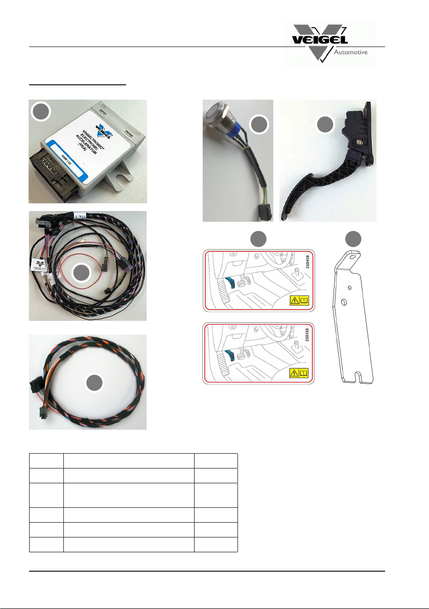
Scope of delivery ............................................................................................... 3-2
Block diagram ..................................................................................................... 3-3
Intended use ....................................................................................................... 3-4
Assembly....................................................................................................4-1
Safety information............................................................................................... 4-1
Tightening torques .............................................................................................. 4-1
Installing the additional accelerator pedal........................................................... 4-2
Installing the additional accelerator pedal........................................................... 4-3
Installing the additional accelerator pedal........................................................... 4-4
Connecting the universal adapter ....................................................................... 4-5
Accelerator pedal signal/pin assignment ............................................................ 4-6
Assembling the VEA ........................................................................................... 4-7
VEA functional check .......................................................................................... 4-7
Teaching in the VEA............................................................................................ 4-8
Button with integrated status LED ...................................................................... 4-9
Laying the cables................................................................................................ 4-9
Prosthetics guard holder................................................................................... 4-10
Checking the function ....................................................................................... 4-10
Disassembling the driving aid ........................................................................... 4-10
Operation....................................................................................................5-1
Operation of the electronic switchover................................................................ 5-2
Safety information............................................................................................... 5-5
Causes of faults .................................................................................................. 5-5
Maintenance and care...............................................................................6-1
Safety information............................................................................................... 6-1
Maintenance/care ............................................................................................... 6-1
Transport, storage and disposal ..............................................................7-1
Transport and storage......................................................................................... 7-1
Disposal .............................................................................................................. 7-1
Installation record .....................................................................................8-1
Blank page for your notes................................................................................... 8-2
Legal provisions........................................................................................9-1

1-2
Contents
Revision history
Edition Revisions Chapter
01 / 2019-09-26 Initial version
02 / 2020-01-28 Editorial revision
3-1
3-3
4-1
4-2
5-2
5-3
5-4
5-5
5-8
03 / 2020-03-12 Editorial revision
5-6
5-7
5-8
04 / 2020-03-25 Editorial revision 3-2
05 / 2020-07-22 Editorial revision (point 5 removed) 4-1
06 / 2020-07-23 Chapter 4 replaced 4-1
07 / 2021-02-22 Chapters 4 and 5 corrected

Contents
1-3
Symbols used
The following symbols are used in these operating instructions:
This symbol refers to tips and recommendations.
This symbol refers to information that, if not observed, will pose a risk to your
health or the functionality of the device.
This symbol refers to important additional information.
NOTE
ATTENTION!
Veigel hotline
Veigel GmbH + Co. KG
Verrenberger Weg 36
74613 Öhringen, Germany
Telephone: +49 (0) 7941 60585-0
Fax: +49 (0) 7941 60585-20
E-mail: info@veigel-automotive.de
Web: http://www.veigel-automotive.de/

1-4
Contents
Blank page for your notes

2-1
General information
Observe the following in particular during assembly:
• Installation and maintenance work may only be performed by specialist sta
using suitable tools.
• Please read these installation and operating instructions carefully before in-
stalling the driving aid.
• Pass the installation and operating instructions for the driving aid on to the
customer, together with any parts certicate, when you hand over the vehicle.
• Observe the applicable accident prevention and safety provisions when in-
stalling and maintaining the driving aid!
• Only accessories obtained from the manufacturer may be used with the
driving aid.
• Structural modications to the driving aid may only be performed following
consultation with the manufacturer.
• If the driving aid is installed in an authorised workshop, the installation re-
cord must be lled in (see appendix). If it is installed at the factory, a sep-
arate installation record will be prepared and archived at the Veigel factory.
General information
General safety information
The driving aid is a universal installation kit, which must be adapted to the
specic vehicle in which it is being tted.
It was designed and built in line with the harmonised standards that must
be observed as well as further technical specications. Consequently, it
is a state-of-the-art product and provides the best possible level of safety
while in operation. The driving aid left the factory in a awless condition in
terms of technical safety.
However, safety can only be achieved in practice if all the required actions
have been taken. The person responsible for operation has a duty to plan
these actions and monitor their implementation.
ATTENTION!

2-2
General information
Observe the following in particular as a user:
• Comply with generally accepted codes of practice when using and oper-
ating the driving aid!
• Observe the applicable accident prevention and safety provisions when op-
erating the driving aid!
• The driving aid may only be operated if it is in a awless, functional condi-
tion. Arrange for functional faults to be remedied immediately.
• Only use the driving aid with the type(s) of vehicle for which it is intended
(see INTENDED USE).
• Always keep the complete installation and operating instructions inside the
vehicle.
• If the vehicle is not driven by a disabled person, then the driving aid must be
removed or taken out of operation. You will nd details on this in the further
applicable documentation.
If this information is not observed, this will void the warranty, the manu-
facturer’s liability and, in certain situations, the type approval. As a con-
sequence, no claims can then be made against us.
NOTE
ATTENTION!
ATTENTION!
The driving aid features built-on parts and levers that will restrict the space
available on the driver’s side to a certain extent once installed.

3-1
Product description
Product description
Function
The electronic left-foot accelerator (type VEA) consists of a second accelerator
pedal, which is connected to the original accelerator pedal via safety electronics.
Before setting o, the driver must decide which pedal they will use. The elec-
tronics make it impossible to switch between the pedals while driving.
The driver can depress the inactive pedal fully and it will have no function.
The electronic left-foot accelerator meets the stringent provisions laid down by
the automotive industry.
Type plate
The type plate and factory number are important when it comes to uniquely
identifying the scope of delivery.
Unique order number
Unique serial number of the driving aid
Type designation
Veigel GmbH + Co. KG 74613 Öhringen
Type: LF Version:
Type designation:
Factory no.: xxxxxx-xxx
Article no.: BLF00006
Please enter the factory number of the driving aid here:
Factory no.: ______________________________
The type plate is stuck on the VEA safety electronics and on the packaging.
Do not install and operate the VEA-type electronics kit in Groupe PSA
vehicles.
ATTENTION!

3-2
Product description
Scope of delivery
Fig. 3-1 Scope of delivery (example)
Item Description Art. no.
1VEA electronics kit 230645
2VEA left-foot accelerator cable
set 230410
3Accelerator pedal module 230124
4Sticker 250458
5Holder 101510
1 3
54
1
2
1

3-3
Product description
Block diagram
Teach-in
adapter
ECU
Switchover button
VEA
Power supply
Original
accelerator
pedal
Veigel
additional
accelerator
pedal

3-4
Product description
Fig. 3-2: Electronic left-foot accelerator installed
Intended use
Use the VEA universal kit to install the accelerator in automatic vehicles that do
not have a vehicle-specic conversion kit.

4-1
Assembly
Assembly
Please note:
• Thedrivingaidmayonlybeassembledbyspecialiststausingsuitabletools.
• Go through the assembly instructions step by step.
• Drill, saw, cut and screw carefully in order to ensure that cables, heating pipes
and similar components are not damaged.
• Carefully seal all screw and drill holes.
Safety information
ATTENTION!
Tightening torques
The tightening torques as specied by the vehicle manufacturer apply when
converting vehicles using Veigel driving aids.
Unless otherwise stated in the text, the usual DIN tightening torques provided
in the table below apply for Veigel parts.
ATTENTION!
Please be advised that only appropriately trained personnel may work on
the vehicle electrics.
Coarse thread
Dimension Tightening torque (Nm)
8.8 10.9
M4 34,4
M5 5,9 8,7
M6 10 15
M8 25 36
M10 49 72
M12 85 125
M14 135 200
M16 210 310
Fine thread
Dimension Tightening torque (Nm)
8.8 10.9
M8x1 27 39
M10x1 55 81
M10x1,25 52 76
M12x1,25 93 135
M12x1,5 89 130
M14x1,5 145 215
M16x1,5 225 330

4-2
Assembly
Installing the additional accelerator pedal
Create a vehicle-specic holder
to enable you to assemble the
second additional accelerator
pedal in the vehicle.
See Fig. 4-1 to 4-3 for examples of
such a holder and how to fasten it.
Fasten this holder to the available
screw points as a rst preference
or, alternatively, to new drill holes
you have made in the vehicle.
When drilling, pay attention to
any cables or lines that have
been laid.
ATTENTION!
Fig. 4-1: Holder, example
Fig. 4-2: Holder, example
Fig. 4-3: Holder, example
Make sure that there is a gap of 50 mm between the additional accelerator
pedal and the brake pedal to rule out the possibility of operating errors.
Also make sure that the accelerator and brake pedal plate is not elevated.
ATTENTION!

4-3
Assembly
See Fig. 4-4 for examples of how
to install the fastenings for the ad-
ditional accelerator pedal.
Fig. 4-4: Example installation
Installing the additional accelerator pedal

4-4
Assembly
Fig. 4-5: Example installation
Fig. 4-6: Example installation
Fig. 4-7: Example installation
Installing the additional accelerator pedal
See Fig. 4-5 to 4-7 for examples of
how to install the fastenings for the
additional accelerator pedal.

4-5
Assembly
Connecting the universal adapter

4-6
Assembly
To nd out how the pins and signals are assigned, use a multimeter to test the
cables on the original accelerator module. The following signals are usually
present: 2x supply voltage, 2x signal cables+, 2x earth.
You can enter the signals you have measured in the table printed below.
Connect the cables correctly according to the pin assignment.
Accelerator pedal signal/pin assignment
Cable
colour Wiring harness sig-
nals Measured
signals Measured cable
colour
Orange 5 V
Purple 5 V
Grey Earth
Blue Earth
White Pot. output (high)
Pink Pot. output (low)
NOTE
The connection for the accelerator pedal must be soldered.
A soldered connection is the only way to ensure signals will be transmitted reliably.
Crimp connections or similar are not permitted.

4-7
Assembly
Connect the plug to the VEA box.
Fasten all loose cables
and check that the relevant
plugs are seated securely.
Re-attach the trim panel to the
dashboard in the driver's side
footwell.
Assembling the VEA
Fig. 4-8: Plug detached from VEA box
• Start the vehicle. The VEA should be adjusted to the original accelerator pedal.
Make sure that the original accelerator pedal is active and working correctly.
Switch the vehicle o.
• Start the vehicle again and, within the next 6 seconds, press the switchover
button once for 1 second to change the pedal.
• If controlled accelerating is not working properly, check all plugs and make
sure that the cabling is correct.
• The default setting on delivery is Mode 1; Mode 1 = automatic switchover to
the original accelerator pedal. This happens each time the vehicle restarts.
ATTENTION!
VEA functional check
Fig. 4-9: Plug attached to VEA box
Fig. 4-10: Power supply for VEA box
Connect the power supply between
the VEA and the vehicle:
Terminal 15 – black cable
Terminal 30 – red cable
Earth – brown cable
It is recommended to disconnect
terminals 15 and 30, preferably in
the fuse box.

4-8
Assembly
Teaching in the VEA
1. Ignition o
2. Plug the TEACH-IN adapter into
the black mating connector.
3. Ignition on
4. Status LED ashes slowly (ready
for teach-in)
5. Status LED flashes quickly
(wiring error; start from point 1 to
rectify it)
6. Fully depress the original accel-
erator pedal module (hold down for
approx. 2 s)
7. Fully depress the additional ac-
celerator (hold down for approx.
2 s)
8. Press the button for approx. 1 s
to conrm the teach-in process
(5x slow ashing means teach-in
was successful, go to point 10/
fast ashing means teach-in was
unsuccessful)
9. If teach-in was unsuccessful,
start from point 1. If the process
fails again, perform troubleshooting
and, after rectifying the error, go to
point 1
10. Ignition o
11. Unplug the TEACH-IN adapter
12. Ignition on and test
Fig. 4-11: Teaching in the VEA
The teach-in process must have been completed successfully prior to
commissioning.
ATTENTION!
Table of contents
Other Veigel Automobile Accessories manuals