Towbar Fitting Instructions
To Suit HOLDEN VF COMMODORE SEDAN 2013 ON
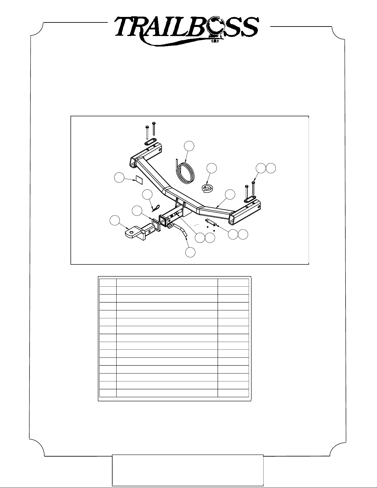
Part Number QTHD519L
Rating 2100/210 kg
PLACE THESE INSTRUCTIONS IN THE VEHICLE’S GLOVEBOX AFTER INSTALLATION IS COMPLETED
Rev: D Page 1 Issue Date: 27-3-2015
Cequent Customer Service
Ph: 1800 812 017 Fax: 03 9898 3299
Email: info@cequent.com.au
Post: PO Box 4050, Dandenong South VIC 3175
FOR TRAILER TOWING PURPOSES ONLY
For towing capacity details please refer to vehicle owner’s
manual or to the manufacturer. Overloading can void your
warranties.
WARNING:
1. Do not, drill, cut, weld or otherwise modify the tow bar.
2. If you are using electric welding on a motor vehicle, always check that the vehicle is not equipped with electronic
engine or instrument management equipment. Failure to do so could destroy any onboard computers. If in
doubt, check with the vehicle's manufacturer.
3. The high tensile fasteners supplied with this product were used to achieve the specified rating. If replacement is
required ensure that fasteners of the same rating & quality are used. Contact an authorised Trailboss dealer if
further information is required.
General:
1. Ensure all hardware items have been included refer to assembly diagram.
2. It is recommended that the instructions are read through and completely understood before making any attempt
to fit this product.
3. Be wary of any changes to vehicle designs or other accessories that may conflict with the installation of this
product.
4. Before drilling ensure that the area is clear of fuel, electrical & other components.
5. All holes drilled into the body panels shall have all burrs & swarf removed then coated with a suitable rust
preventative paint.
6. For vehicles that require the bumper to be cut. Ensure cut out area is in correct position on the vehicle prior to
cutting the bumper.
7. The high tensile fasteners supplied with this product were used to achieve the specified rating. If replacement is
required ensure that fasteners of the same rating & quality are used. Contact an authorized Trailboss dealer if
further information is required.
8. Ensure that all hardware is fastened to torque list below check fasteners on regular basis.
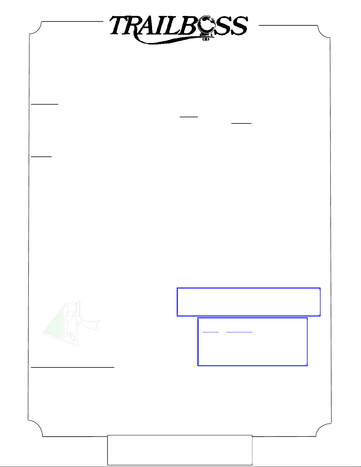
9. Tow bar load rating sticker provided with this product shall be conspicuously located on inside rear end of the
driver's door. (See diagram below).
10. Trailboss recommends that you check your tow ball to ensure that it complies with the Australian standards
AS 4177.2.
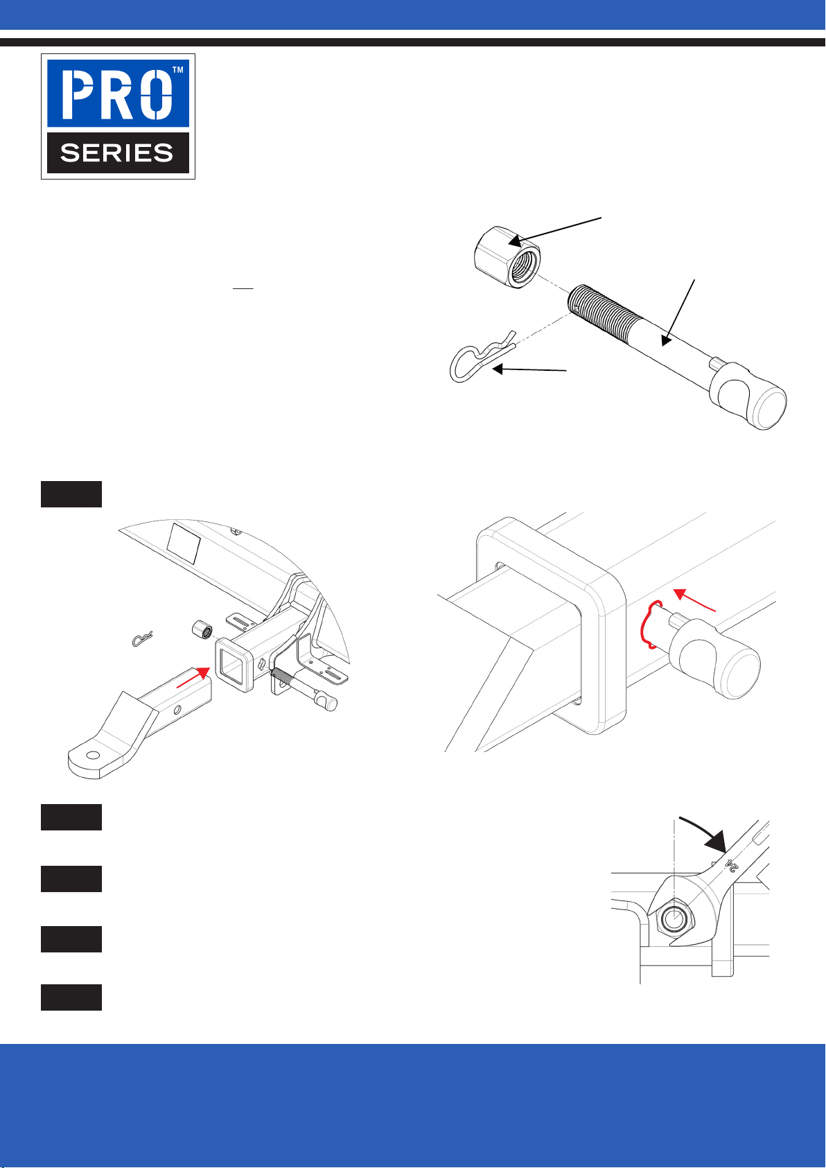
11. PLEASE NOTE: It is advised to remove your lug or tbm when not actually towing so as to produce a clear view of
the vehicles registration plate if obscured, and to also provide maximum available departure angle
12. Pull Pin must be fit in down position.
Tow bar Maintenance and Care.
Trailboss recommends that bolt torque’s, as listed below, are routinely and regularly inspected and checked for correct
tension. Replace any worn or defective parts.
We recommended to remove Tow Ball Mounts (TBM’s, tongues or lugs) when not being used for any considerable length
of time.
So as to avoid injury, when not towing it is suggested that the tongue, Pull Pin and R-clip are removed then stored in a
safe, clean and dry place, away from excessive moisture.
Hitch Pull Pins and spring “R” clips are regularly checked for proper installation. Replace any worn or defective parts.
Place load rating sticker
inside driver’s door here RECOMMENDED ASSEMBLY TORQUE LISTING
Diameter Grade 8.8 Bolt
M6 9.5 Nm
M8 21.7 Nm
M10 43.4 Nm
M12 77.3Nm
M14 146 Nm
M16 189.8 Nm