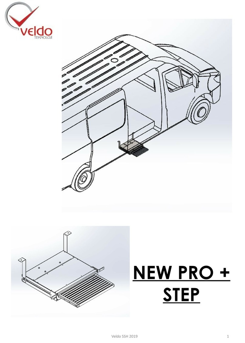
Veldo Teknoloji DUCATO User manual

DUCATO
VELDO SSH 1
AUTOMATIC SLIDING DOOR AND STEP
SYSTEMS

•Main components of door system ……………………………… 3 - 9
•Advantages of door system ……………………………… 9 – 10
•Security systems of door system .……………………… 10
•Working way of door system ……………………..……10
•Assembling of door system ……………………………… 11 – 25
•Working and control of door system ………………… 36 – 29
•Maintanance of door system ……………………………… 30
•Warranty terms of door system …………….…..………… 30 – 31
•Fault diagnosis at door system …………………………. 32
CONTENTS
VELDO SSH 2

MAIN COMPONENTS OF DOOR SYSTEM
NO.
PART DESCRIPTION
1
FRONT FOOT GROUP
2
MOTOR (ENGINE) GROUP
3
MIDDLE FOOR GROUP
4
BELT TURNBUCKLE GROUP
5
REAR FOOT
VELDO SSH 3

MAIN COMPONENTS OF DOOR SYSTEM
Electrical Wiring: It provide to movement and signal control of
automatic door.
In-door electrical wiring: It provides to spent less power of
automatic door for bring from the open position to the closed
position
Door drive mechanism: it is the part that contains the system units and is placed under the
automatic door on the vehicle chassis.
VELDO SSH 4
Control Unit

MAIN COMPONENTS OF DOOR SYSTEM
Unbolting System: It is the mechanism that automatically opens the
door without changing the original lock mechanism of the vehicle
door.
Motor(Engine) Group
Lock Puller System: The automatic door ensures that less force is
exerted to bring it from the open position to the closed position.
Cable Sheaves: Cable sheaves absorb the belt looseness that occurs
during sudden changes in direction of the automatic door.
Movement Sheaves: Allows you to complete the motion in a
frictionless manner by determining the direction of motion.
VELDO SSH 5

MAIN COMPONENTS OF DOOR SYSTEM
Encoder: It allows automatic position information of the door to
be transferred to the control unit and distance adjustment can
be made.
RF receiver cable
Bottom engine grasp cable
Main system engine socket
VELDO SSH 6

MAIN COMPONENTS OF DOOR SYSTEM
( - ) ve ( + ) points of main system wiring
Note: This has to be connected to the vehicle's battery.
123
45
678
Main wiring cable points
1. km (speed ) signal cable
2. Ignition open signal cable
3. Lock pulling cable
4. Middle door remote control signal
5. Reedrelay cable
RF transmitter module
Note: RF transmitter module is installed inside the
door
VELDO SSH 7
Main wiring cable points
6. Front panel button cable
7. Front door signal cable
8. Wick shoot cable

MAIN COMPONENTS OF DOOR SYSTEM
The way the RF receiver module is installed.
Unbolting engine
cable
Door handle switch
cable
Security wick
cable
Switch signal and motor
lock signal points will be
connected here
Inner door wiring cable points
VELDO SSH 8

SECURITY SYSTEMS OF VELDO DOOR
Security wick: The automatic door allows the door to open
automatically in case of any obstruction or jamming.
Overcurrent control: It is a security system that is switched on when the security wick is disabled.
User controlled security system: When the door is automatically closed, the door automatically
opens when the user commands from the front panel button or the door opening lever.
VELDO SSH 9
Audible and light warning system: If the automatic door is opened through the door opening
handle while the vehicle is moving or stopping, the user is alerted by voice. There is a short tone
audible warning during closing, long tones interrupted and audible warning during opening.
As the door opens and closes, the control unit gives an audible warning.
When the door is open, the user is alerted by the light on the front panel button.

SECURITY SYSTEMS OF VELDO DOOR
Speed-controlled safety system: When the vehicle is moving when the vehicle speed is above a
certain limit (5 km / h) and the door is not open and the door is open; it automatically closes when
a certain speed limit (5km / h) is exceeded. Also, if the sliding door is attempted to open manually
from the inside when the vehicle is moving, the system prevents the door from opening.
In case of accident or emergency: In case of emergency, the vehicle door can be opened manually
from the inside and outside from the original door opening levers manually
WORKING WAYS OF VELDO AUTOMATIC DOOR SYSTEM
1 -With the on / off button mounted on the front chest
2 –With original remote control of vehicle
VELDO SSH 10

ASSEMBLING OF AUTOMATIC DOOR
Driver and passenger seats are first removed and removed from
the car in order to mount Veldo automatic sliding doors.
The batteries under the driver's seat of the vehicle are removed
as shown in the figure.
VELDO SSH 11
Ø 12 mm punch hole is drilled for take wirings under the vehicle.

ASSEMBLING OF AUTOMATIC DOOR
The wiring is put under the vehicle through the holes drilled. The
section on the top of the vehicle is as seen in the figure.
Images of the wiring under the vehicle are like the way.
VELDO SSH 12

VELDO SSH 13
ASSEMBLING OF AUTOMATIC DOOR
The security wick is
installed according to
the form of the door.
Security wick the cable pass hole
is drilled from the spot marked in
the figure.
The security wick cable is
connected to the inner door
installation color to color.

VELDO SSH 14
ASSEMBLING OF AUTOMATIC DOOR
Cutting process is done with air saw.
It is then cut from drawn places.
Centering is done according to the
original equivalent for the lock puller
mechanism.
It is marked with the corresponding
sheet as shown in the figure.
The vehicle's original lock counterpart
is dismantled.

VELDO SSH 15
ASSEMBLING OF AUTOMATIC DOOR
It is drilled from corners with Ø 10 mm drill.
The cut is done as in the figure.
The lock puller mechanism
is installed as shown in the
picture. (from outside)
The cut is done as in the figure.

VELDO SSH 16
ASSEMBLING OF AUTOMATIC DOOR
The lock puller mechanism is
installed as shown in the
picture. (from inside)
The front mast connection is connected according to the diagram.
The door on/off button cable plugs in the main system
installation are attached to the button. The panel is then
assembled into place.
- = White,
+ = Red,
COM = White-blue
ON = Black

ASSEMBLING OF AUTOMATIC DOOR
VELDO SSH 17
40 mm and 60 mm marks are made for the rear foot
connection by reference to the region seen in the
figure.
Ø 30 mm punch hole is drilled from the marked area.
Rear foot assembly is done.

VELDO SSH 18
ASSEMBLING OF AUTOMATIC DOOR
The parts seen in the figure are cut with the help of an
air saw.
The cut section is as seen in the figure.
The parts seen in the figure are cut with the help of an
air saw.
The cut section is as seen in the figure.

VELDO SSH 19
ASSEMBLING OF AUTOMATIC DOOR
The area shown in the figure is cut for the main chassis
assembly.
The cut section is as seen in the figure.

ASSEMBLING OF AUTOMATIC DOOR
VELDO SSH 20
The original foot of the vehicle is removed for the belt
connection process.
The belt mounting bracket is connected to the original
foot of the vehicle as shown in the figure.
Other Veldo Teknoloji Automobile Accessories manuals
Popular Automobile Accessories manuals by other brands

Brink
Brink 3615 Fitting instructions

Tactical 4x4
Tactical 4x4 LR3 Rear Tire Carrier installation instructions

Adaptiv Mini
Adaptiv Mini CAM-AU9-AD FITTING & USER GUIDE

Havis-Shields
Havis-Shields KK-K9-D22-K installation instructions

Saris
Saris The T-Rax Sport installation manual

HSP
HSP Tail Lock Fitting instructions