Velleman K6707 User manual

Total solder points: 170
Difficulty level:
beginner 1o2þ3o 4o 5oadvanced
K6707
CODELOCK RECEIVER
ILLUSTRATED ASSEMBLY MANUAL H6707IP-2
Features:
Specifications :
þRelay output: 10A toggle or momentary contact.
þSeparate output to switch car alarm on or off.
þPower supply: 2 x 9VAC or 12 to 16VDC / 100mA max.
þDimensions: 76 x 84mm / 3 x 3,4”
* modifications reserved.
þEasy to build: no coils to be made!
þOperates in conjunction with the K6706 two channel transmitter.
þ8.748 possible codes.
þRange of the transmitter/receiver: +/-30m.
þLED on/off indication.
þLED receiving level indicator.

2
VELLEMAN Components NV
Legen Heirweg 33
9890 Gavere
Belgium Europe
www.velleman.be
www.velleman-kit.com

3
1. Assembly (Skipping this can lead to troubles ! )
Ok, so we have your attention. These hints will help you to make this project success-
ful. Read them carefully.
1.1 Make sure you have the right tools:
•A good quality soldering iron (25-
40W) with a small tip.
•Wipe it often on a wet sponge or cloth, to keep it clean; then apply solder to the
tip, to give it a wet look. This is called ‘thinning’ and will protect the tip, and en-
ables you to make good connections. When solder rolls off the tip,
it needs cleaning.
•Thin raisin-core solder. Do not use
any flux or grease.
•A diagonal cutter to trim excess wires. To avoid injury
when cutting excess leads, hold the lead so they
cannot fly towards the eyes.
•Needle nose pliers, for bending leads, or to hold components in
place.
•Small blade and Phillips screwdrivers. A basic range is fine.
For some projects, a basic multi-meter is required, or
might be handy
1.2 Assembly Hints :
⇒Make sure the skill level matches your experience, to avoid disappointments.
⇒Follow the instructions carefully. Read and understand the entire step before you
perform each operation.
⇒Perform the assembly in the correct order as stated in this manual
⇒Position all parts on the PCB (Printed Circuit Board) as shown on the drawings.
⇒Values on the circuit diagram are subject to changes.
⇒Values in this assembly guide are correct*
⇒Use the check-boxes to mark your progress.
⇒Please read the included information on safety and customer service
* Typographical inaccuracies excluded. Always look for possible last minute manual
updates, indicated as ‘NOTE’ on a separate leaflet.
0.000
Assembly hints

4
1.3 Soldering Hints :
Mount the component against the PCB surface and carefully solder the
leads
Make sure the solder joints are cone-shaped and shiny
Trim excess leads as close as possible to the solder joint
REMOVE THEM FROM THE TAPE
ONE AT A TIME !
Velleman hereby certifies that the device K6707 meets
the essential requirements and all other relevant stipulations of directive
1999/5/EG and 1995/5/EC.
For the complete conformity declaration check out :
http://www.velleman.be/downloads/doC/CE_K6707.pdf
AXIAL COMPONENTS ARE TAPED IN THE CORRECT
MOUNTING SEQUENCE !
Assembly hints

IPESF SDK NDGB FNL
C
O
D
E
CODICE
COLORE CODIGO
DE CORES CODIGO
DE COL-
ORES
VÄRI
KOODI FÄRG
SCHEMA FARVE-
KODE FARGE-
KODE FARB
KODE COLOUR
CODE CODIFI-
CATION
DES COU-
LEURS
KLEUR
KODE C
O
D
E
0Nero Preto Negro Musta Svart Sort Sort Schwarz Black Noir Zwart 0
1Marrone Castanho Marrón Ruskea Brun Brun Brun Braun Brown Brun Bruin 1
2Rosso Encarnado Rojo Punainen Röd Rød Rød Rot Red Rouge Rood 2
3Aranciato Laranja Naranjado Oranssi Orange Orange Orange Orange Orange Orange Oranje 3
4Giallo Amarelo Amarillo Keltainen Gul Gul Gul Gelb Yellow Jaune Geel 4
5Verde Verde Verde Vihreä Grön Grøn Grønn Grün Green Vert Groen 5
6Blu Azul Azul Sininen Blå Blå Blå Blau Blue Bleu Blauw 6
7Viola Violeta Morado Purppura Lila Violet Violet Violet Purple Violet Paars 7
8Grigio Cinzento Gris Harmaa Grå Grå Grå Grau Grey Gris Grijs 8
9Bianco Branco Blanco Valkoinen Vit Hvid Hvidt Weiss White Blanc Wit 9
AArgento Prateado Plata Hopea Silver Sølv Sølv Silber Silver Argent Zilver A
BOro Dourado Oro Kulta Guld Guld Guldl Gold Gold Or Goud B
5%
4K7= ( 4 - 7 - 2 - B )
1%
4K7= ( 4 - 7 - 0 - 1 - 1 )
COLOR= 2… 5
COLOR= 2...5

6
qR1 : 270 (2-7-1-B)
qR2 : 18K (1-8-3-B)
qR3 : 18K (1-8-3-B)
2. 1/4W Resistors
R...
qJ
1. Jumper wires
Construction
By using the jumpers, the receiver can be set up for two
output possibilities:
1. The output is on while the transmitter is pressed
(MOMENT), this is mostly used for operating a door lock,
garage door etc.
2. The output switches (on/off) every time the transmitter is
pressed (toggle), this setting is mostly used for switching
alarms in and out, for operating central door locking systems,
for switching a lamp on and off, etc. This setting must be
used for use with our car alarm K3504.
NOTE :
qR4 : 33K (3-3-3-B)
qR5 : 5K6 (5-6-2-B)
qR6 : 2K7 (2-7-2-B)
qR7 : 6K8 (6-8-2-B)
qR8 : 6M8 (6-8-5-B)
qR9 : 1K (1-0-2-B)
qR10 : 1K (1-0-2-B)
qR11 : 100K (1-0-4-B)
qR12 : 47K (4-7-3-B)
qR13 : 47K (4-7-3-B)
qR14 : 470 (4-7-1-B)
qR15 : 470K (4-7-4-B)
qR16 : 10K (1-0-3-B)
qR17 : 10K (1-0-3-B)
qR18 : 10K (1-0-3-B)
qR19 : 220K (2-2-4-B)
qR20 : 680 (6-8-1-B)
qR21: 2K2 (2-2-2-B)

7
Construction
qZD1 : 4V3
qZD2 : 4V7 (5V1)
4. Zener diodes
Watch the polarity !
CATHODE
ZD...
qL1 : 1µH (1-0-B)
5. SAW resonator
L2
L...
qIC1 : 18p
qIC2 : 8p
qIC3 : 14p
qIC4 : 14p
7. IC sockets.
(check the position of the notch)
IC...
1
qC1: 2pF(2p2)
qC2: 2pF (2p2)
qC3: 22pF
qC4: 82pF
qC5 : 330pF (331)
qC6 : 330pF (331)
qC7 : 330pF (331)
qC8 : 100nF (104, µ1)
qC9 : 100nF (104, µ1)
6. Capacitors
C...
qD1 : 1N4148
qD2 : 1N4148
qD3 : 1N4148
qD4 : 1N4148
qD5 : 1N4148
qD6 : 1N4000 … 4007
qD7 : 1N4000 … 4007
3. Diodes
Watch the polarity !
D...
CATHODE

8
Construction
qLD2: 3mm
9. LED.
Watch the polarity !
COLOR= 2...5
LD...
CATHODE
qT1: BF199
qT2: BC547
qT3: BC547
10. Transistors.
T...
T...
T...
T...
T...
qC10 : 1µF
qC11 : 1µF
qC12 : 1µF
qC13 : 1µF
qC14 : 1µF
qC15 : 470µF
8. Capacitors.
Watch the polarity !
C...
qVR1 : 7809
12. Voltage regulator
qCV1 : 5pF (5p5)
11. Capacitive trimmer
VR...
qJ1 : 3 -pole
qJ2 : 3 -pole
qJ3 : 3 -pole
13. Screw connector
CV...

9
Construction
qIC1 : UM3758-120A
qIC2 : RV4558 -LM258 -
2904
qIC3 : CD4013
qIC4 : CD40106
15. ICs
(check the position of the notch)
IC...
PIN 1
1
qRY1 : VR10V12
14. Relays
RY...
Affix the supplied sticker to the
housing.
16. Sticker
Velleman
SRFCE
433,92 MHz

10
You can select your own code for a transmitter/receiver com-
bination. There is a 9 row jumper island located directly next
to IC1 for setting the code. The code is set by connecting
one or more code points to a neighboring ‘+’ or ‘-‘ point using
the small jumpers. Code points may also be left unconnected
(open): see figure.
a) No connection
b) Code connection to ‘-’
c) Code connection to ‘+’
d) Example of a possible code
Note: certain points cannot be connected to ‘+’
Personal code
17. Create your code

11
IMPORTANT:
•A plastic screwdriver (including plastic blade) is needed to tune
the transmitter or receiver. This is supplied with the receiver.
•The transmitter must be in its housing with the cover off.
•The receiver may not be in the vicinity of any metal objects.
•The transmitter and receiver must have the same code.
•If it is to be operated from push button SW1 of the transmitter,
jumper CH1 of the receiver must be set. Otherwise, jumper
CH2 must be set for operation from push button SW2.
1) Tuning receiver:
•Set the tuning capacitor of the receiver to around the
middle of its adjustment range.
•Check that the tuning LED of the receiver is not lit up, or is just
on the verge of lighting up. If not, the tuning capacitor will have
to be adjusted a little. Do not touch the circuit with your hand.
2) Tuning one or more transmitters to the receiver:
•Activate the transmitter (do not touch any other parts
other than the push button) and then (very carefully) turn
the tuning capacitor until the tuning LED of the receiver
lights up. If everything is correct, the relays should now
switch, if of course the codes of the transmitter and re-
ceiver are the same.
•Now take the transmitter to a distance of about 10 metres
from the receiver and repeat the test. Then the transmitter
can be tested from around 20 metres (perhaps ask some-
body to help you).
•If the transmitter cannot be tuned to the receiver, then it
might be that the tuning capacitor of the receiver needs to
be adjusted.
18. Test and set-up
Test & set-up
12
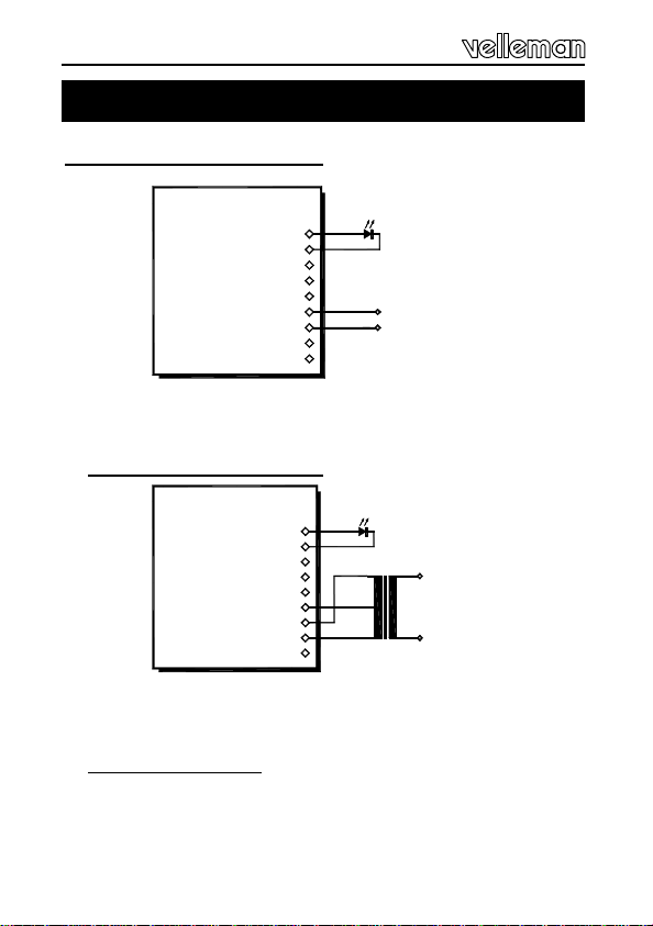
1. Connection to DC voltage :
Fig. 1.0
E.g. : car battery
2. Connection to AC voltage :
Fig. 2.0
E.g. : 2 x 9VAC / 100 mA Transformer
3. Other connections :
When using the relay output there is a choice between a
normally closed contact (NC) or a normally open contact
(NO). The common output is at COM.
Connection
19. Connection
A
C
COM
NO
NC
GND
VA
VB
DIS
-
+
12 ... 16vdc
K6707
LD1
A
C
COM
NO
NC
GND
VA
VB
DIS
K6707
LD1
L
N
MAINS
9VAC
9VAC
TRANSFO
13
Connection
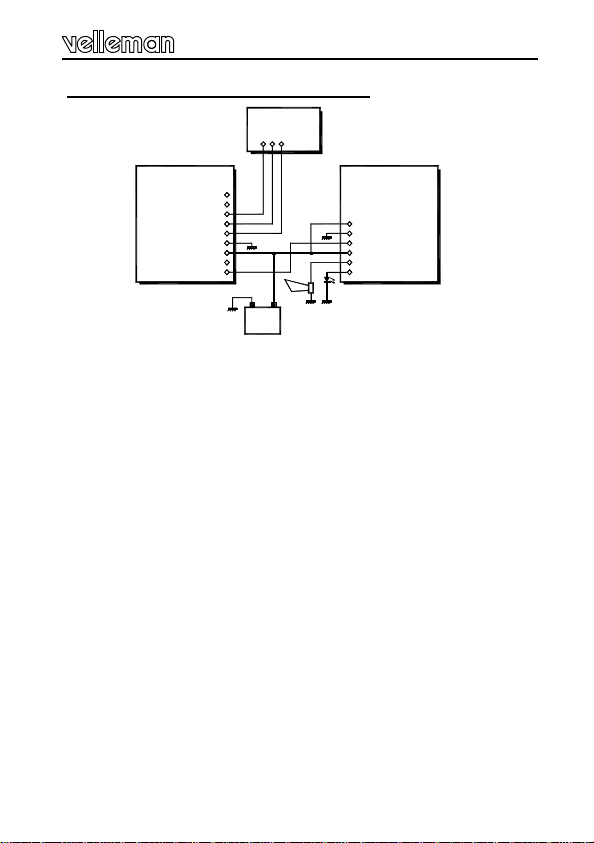
4. Connection to the k3504 car alarm :
Fig. 3.0
For connection to the K3504 car alarm the DIS points of both
circuits must be connected together. In this case the "DIS" con-
nection of the car alarm must not be connected to the contact
lock. For remote controlled operation of the car alarm, the
SWITCHING TIME (IN and OUT) can be set to minimum. The
free relay contacts can be still be used to operate the central
locking system for example.
For indication purposes, LED LD1 can be mounted somewhere
on the dashboard using the LED holder supplied. When the relay
is closed the LED will flash, when open it is continuously lit.
NOTE
The circuit can also be installed in a plastic housing.
For installation in the car, the circuit can be mounted some-
where under the dashboard, and preferably in a place where
there are few metal parts. It may be the case that after installa-
tion in the car, the circuit will have to be retuned. This is be-
cause of the influence of metal parts in the vicinity of the circuit.
Because of the earth screen in a car, the transmitter/receiver
range will be approximately halved which in most cases is more
than sufficient.
A
C
COM
NO
NC
GND
VA
VB
DIS
K6707
DOOR LOCK
SYSTEM
ACCU
-+
+
-
DIS
NO
COM
LD1
LD1
K3504

14
PCB layout.
PCB

15
Diagram
Diagram
IC1(UM3758-120A)
FF1,FF2=IC3(CD4013)
N1...N6=IC4(CD40106)
A1,A2=IC2(RV4558)
R13
C12
+V
D6
D7
A2
ZD2
R6
ZD1
9
R14
N4
D4
R12
D2D3
N2
3 4
SET
CLK
RST
4
3
D5FF1
6
Q
8
2NC
Q
1
N3
MOMENTARY
TOGGLE
C11
10 11
SET
CLK
R15
8
Q
13 10
D
FF2
11 12
9
N1
RST
Q
2 1
D1
C1
CV1
R2
C4
R5
R4
T1
C6
C3L2
+V
R1
R8
C10
R9
+V
L1
R7
C7
R3
R10
+V
A11
3
2
64
5
+V
8
C2
VB
VA
GND
A8
C5
VSS
17
R17
C13
R16 T2
RY1
+V1
D5
NO
COM
DIS
N6
NC
12
OUT
13
R18
R20
T3
+V
N5
R19
5 6 LD1
A9
MODE
A10
1514
10
9
8
NC
16
13
12
11
VDD
CH1
7
LD2
+V
R11
OSC
R21
RxIN
7809
C8
C15 C9
VR1
CH2
C14
+V
A12
A11
+
V
1
A7
A6
A5
7
IC1
6
5
A4
A3
A2
3
4
2
+V
A1
18
1
+V

16
Modifications and typographical errors reserved
© Velleman Components nv.
H6707IP -2002 -ED2
Other Velleman Receiver manuals

Velleman
Velleman PMRSET User manual

Velleman
Velleman K8070 User manual

Velleman
Velleman VM160 User manual

Velleman
Velleman BTR1 User manual

Velleman
Velleman DVBTUSB2 User manual

Velleman
Velleman PMR3SET User manual

Velleman
Velleman AVMOD15 User manual

Velleman
Velleman ED85009 User manual

Velleman
Velleman K6713 User manual

Velleman
Velleman DVBTR User manual

Velleman
Velleman DVBTR2 User manual

Velleman
Velleman AM6621 User manual

Velleman
Velleman VM119 User manual

Velleman
Velleman VMM004 User manual

Velleman
Velleman PMR2 User manual

Velleman
Velleman DVBTR6 User manual

Velleman
Velleman PMR4SET User manual

Velleman
Velleman AVMOD8 User manual

Velleman
Velleman VAS5R User manual

Velleman
Velleman VM122 User manual


