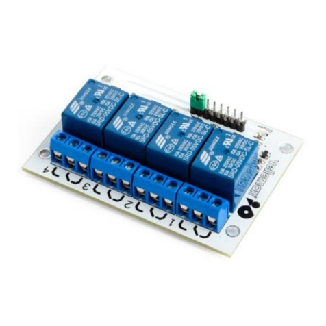
Velleman VM129 User manual

VM129
8-channel relay card 3
8-Kanaals relaiskaart 10
8-Kanal-Relaiskarte 24
Tarjeta relé de 8 canales 31
EIGHT CHANNEL RELAY CARD
Carte relais à 8 canaux 17


3
Thank you for purchasing this module. Please read the instructions carefully to ensure correct and safe use of this device.
WARRANTY
This product is guaranteed against defects in components and construction from the moment it is purchased and for a period of TWO YEAR starting from the
date of sale. This guarantee is only valid if the unit is submitted together with the original purchase invoice. VELLEMAN components Ltd limits its responsibi-
lity to the reparation of defects or, as VELLEMAN components Ltd deems necessary, to the replacement or reparation of defective components. Costs and
risks connected to the transport, removal or placement of the product, or any other costs directly or indirectly connected to the repair, will not be reimbursed by
VELLEMAN components Ltd. VELLEMAN components Ltd will not be held responsible for any damages caused by the malfunctioning of a unit.
CONTENTS :
FEATURES & SPECIFICATIONS......................................................................................................................................................... 4
POWER SUPPLY.................................................................................................................................................................................. 5
INPUT CONNECTION EXAMPLES...................................................................................................................................................... 6
OUTPUT CONNECTION EXAMPLE.................................................................................................................................................... 8
SAFETY AND WARNING INSTRUCTIONS......................................................................................................................................... 9
Warnings and contents
READ THE OPERATING AND MAINTENANCE INSTRUCTIONS IN
THIS USER’S GUIDE CAREFULLY.

4
Specifications & features
SPECIFICATIONS & FEATURES
FEATURES
Eight high quality relay contacts, 5A/230VAC max.
Relay outputs are transient suppressed using VDR’s.
LED confirmation on each relay contact.
Eight drive inputs to use with open collectors or regular switches.
Ideal for use with our computer interface card VM110 or infrared remote control receiver VM122.
SPECIFICATIONS
• Power: 12Vac / 500mA (including 12V output)
• Unregulated 12Vdc / 200mA power output (for VM122)

5
Power supply
2
3
1
NO
NO
NO
NO
AC
12V
INPUT
MAINS
1 x 12V / 500mA
Ordernr. Transformer : 112006C
POWER SUPPLY
Choose a suitable location for the unit. Probably, the best location is near
the fuse box. An optional enclosure (B8006) is available, for safe installation
of the unit on a DIN rail.
The drawings on the next pages shows connection examples with different
input possibilities.
Make sure your wiring complies with the local safety requirements.
If doubt, consult a licensed technician !
B8006 Optional Din rail enclosure
Ordernr. Transformer : 112006C

6
Input connection examples
15-channel infrared receiver 'VM122' :
The connection diagram (Fig. 1.0) shows how
to connect relays to the interface card VM122.
The 15 outputs of VM122 are open-collector
outputs, which means they are transistors used
as switches. When an output is active, a closed
contact is created between ground (GND) and
that output.
As shown in the connection diagram, one
single power supply can be used for the re-
ceiver module as well as e.g. for the relay
switch.
Note : You can use the VM121 infrared
transmitter to control your applications.
INPUT CONNECTION EXAMPLES
Figure 1.0
0
2
0
3
1
0
4
0
5
0
6
0
7
0
8
0
+12V
0
IN
NO
6
NO
8
NO
7
5
NO
NO
4
AC
NO
2
NO
3
NO
1
INPUT
12V 1 x 12V / 500mA
MAINS
GND
VB
VA
2
1
+V
7
8
6
5
4
3
13
14
12
11
10
9
+
VCOM
15
0
INPUT
Vout
RS232
VM129VM122
Ordernr. Transformer : 112006C

7
Input connection examples
USB Interface Card 'VM110' : Connection with regular switches :
01
02
03
04
05
06
GND
CLAMP
08
07
DAC1
PWM1
DAC2
PWM2
GND 0
2
0
3
1
0
4
0
5
0
6
0
7
0
8
0
0
+12V
0
IN
RS232
V out
INPUTS
0
2
0
3
1
0
4
0
5
0
6
0
7
0
8
0
0
+12V
0
IN
RS232
V out
INPUTS
Figure 2.0
Figure 3.0
VM129
VM110

8
Output connection example
OUTPUT CONNECTION EXAMPLE
NO
1
230V
230V

9
All repairs should be executed by qualified technicians.
Avoid the installation of the module in locations with standing or running water or excessive humidity. Indoor
use only !
SAFETY INSTRUCTIONS
Handle the module gently and carefully. Dropping it can damage the circuit board.
Never exceed the protection limit values indicated in the specifications.
As safety requirement vary, please check with your local authorities.
Facilitate the operation of the device by familiarising yourself with its adjustments and indications.
Velleman modules are not suitable for use or as part of life support systems, or systems that might create hazardous situations of kind.
WARNINGS
Repair under warranty is only possible with date and proof of purchase.
Safety & warning instructions

10
Hartelijk dank voor de aanschaf van deze module. Lees de gebruiksaanwijzing aandachtig, zodat u het apparaat op de juiste
manier gebruikt.
WAARBORG
Dit produkt is gewaarborgd wat betreft gebreken in materialen en vakmanschap op het ogenblik van de aankoop en dit gedurende een periode van TWEE
JAAR vanaf de aankoop. De waarborg geldt enkel indien het produkt voorgelegd wordt samen met het origineel aankoop bewijs. De verplichtingen van
VELLEMAN COMPONENTS N.V. beperken zich tot het herstellen van defecten of, naar vrije keuze van VELLEMAN COMPONENTS N.V., tot het vervangen
of herstellen van defecte onderdelen. Kosten en risico’s van transport; het wegnemen en terugplaatsen van het produkt, evenals om het even welke andere
kosten die rechtstreeks of onrechtstreeks verband houden met de herstelling, worden niet door VELLEMAN COMPONENTS N.V. vergoed. VELLEMAN
COMPONENTS N.V. is niet verantwoordelijk voor schade van gelijk welke aard, veroorzaakt door het falen van een product.
CONTENTS
KENMERKEN & SPECIFICATIES...................................................................................................................................................... 11
VOEDING............................................................................................................................................................................................. 12
AANSLUITINGSVOORBEELDEN VOOR DE INGANGEN............................................................................................................... 13
AANLSUITINGSVOORBEELD VOOR DE UITGANG....................................................................................................................... 15
VEILIIGHEIDSAANWIJZINGEN EN WAARSCHUWINGEN............................................................................................................. 16
Waarschuwingen en inhoud
LEES DE GEBRUIKS - EN ONDERHOUDSAANWIJZINGEN VAN DE
HANDLEIDING ZORGVULDIG DOOR.
11
Eigenschappen en technische gegevens
EIGENSCHAPPEN & TECHNISCHE GEGEVENS
EIGENSCHAPPEN
8 hoogwaardige relaiscontacten, 5A/230Vac max.
Relaisuitgangen onderdrukken pieken d.m.v. VDRs
Bevestiging via LED op ieder relaiscontact
8 stuuringangen voor gebruik met open collector of gewone schakelaars.
Ideaal in combinatie met onze computer interfacekaart VM110 of infrarood ontvanger VM122.
TECHNISCHE GEGEVENS
• Ingangsvermogen: 12Vac / 500mA (met 12V-uitgang)
• Uitgerust met 12Vdc / 200mA vermogensuitgang (voor voeding VM122)

12
Voeding
2
3
1
NO
NO
NO
NO
AC
12V
INPUT
MAINS
1 x 12V / 500mA
Ordernr. Transformer : 112006C
VOEDING
Kies een geschikte locatie voor de installatie van de unit. Waarschijnlijk zult
u de unit installeren in de nabijheid van een zekeringkast. Een geschikte
behuizing voor DIN-rail montage is leverbaar, zodat de unit op een nette en
veilige wijze kan ingebouwd worden (ordercode B8006).
De figuren op de volgende pagina’s tonen u één van de verschillende
mogelijkheden voor het aansluiten van de ingangen
Zorg ervoor dat de montage en aansluiting voldoet volgens de
geldende veiligheidsvoorschriften. Bij twijfel, raadpleeg een vakman !
B8006 Optionele DIN-rail behuizing
Ordernr. Transformer : 112006C

13
Aansluitingsvoorbeelden voor de ingangen
15- kanaals infrarood ontvanger 'VM122' :
In het bedradingsschema (Fig. 1.0) ziet u hoe u
relais moet aansluiten op de VM122
interfacekaart.
De 15 uitgangen van VM122 zijn “open-
collector” uitgangen: het zijn dus transistors
gebruikt als schakelaar. Bij een actieve uitgang
ontstaat een gesloten contact tussen de massa
(GND) en de desbetreffende uitgang.
Zoals de volgende aansluitschema’s tonen, kan
je één enkele voeding gebruiken voor zowel de
ontvangstmodule als bvb. het relais.
Opmerking : U kunt de VM121 IR zender
gebruiken om uw toepassingen aan te sturen.
AANSLUITINGSVOORBEELDEN VOOR DE INGANGEN
Figure 1.0
0
2
0
3
1
0
4
0
5
0
6
0
7
0
8
0
+12V
0
IN
NO
6
NO
8
NO
7
5
NO
NO
4
AC
NO
2
NO
3
NO
1
INPUT
12V 1 x 12V / 500mA
MAINS
GND
VB
VA
2
1
+V
7
8
6
5
4
3
13
14
12
11
10
9
+
VCOM
15
0
INPUT
Vout
RS232
VM129VM122
Ordernr. Transformer : 112006C

14
Aansluitingsvoorbeelden voor de ingangen
USB interface kaart 'VM110' : D.m.v drukknopen, schakelaars, ... :
01
02
03
04
05
06
GND
CLAMP
08
07
DAC1
PWM1
DAC2
PWM2
GND 0
2
0
3
1
0
4
0
5
0
6
0
7
0
8
0
0
+12V
0
IN
RS232
V out
INPUTS
0
2
0
3
1
0
4
0
5
0
6
0
7
0
8
0
0
+12V
0
IN
RS232
V out
INPUTS
Figure 2.0
Figure 3.0
VM129
VM110

15
Aansluitingsvoorbeeld voor de uitgang
AANSLUITINGSVOORBEELD VOOR DE UITGANG
NO
1
230V
230V

16
Veiligheidsaanwijzingen en waarschuwingen
Reparaties mogen uitsluitend uitgevoerd worden door vakkundige personen.
Installeer de module niet op plaatsen met staand of stromend water of in ruimtes met een te hoge vochtigheidsgraad. Bin-
nengebruik enkel!
VEILIGHEIDSAANWIJZINGEN
Vermijd een ruwe behandeling. Stoten of laten vallen kunnen ernstige schade aanbrengen.
Overschrijdt nooit de opgegeven veiligheidswaarden in de specificaties.
Vermits de veiligheid vereisten verschillen van plaats tot plaats, dient U ervoor te zorgen dat Uw montage voldoet aan de plaatselijke geldende vereisten.
Zorgt ervoor dat u met alle bedieningselementen vertrouwd raakt, wanneer U met het toestel zal werken.
Velleman modules zijn niet geschikt voor gebruik in of als gedeelte van systemen welke levensfuncties in stand houden of systemen welke gevaarlijke
situaties van gelijk welke aard kunnen veroorzaken.
WAARSCHUWING
Herstelling onder garantie is enkel mogelijk met aankoopbewijs.

17
GARANTIE
Ce produit est garanti contre les défauts des composantes et de fabrication au moment de l’achat, et ce pour une période de DEUX ANS à partir de la date
d’achat. Cette garantie est uniquement valable si le produit est accompagné de la preuve d’achat originale. Les obligations de VELLEMAN COMPONENTS
S.A. . se limitent à la réparation des défauts ou, sur seule décision de VELLEMAN COMPONENTS S.A. au remplacement ou à la réparation des pièces
défectueuses. Les frais et les risques de transport, l’enlèvement et le renvoi du produit, ainsi que tous autres frais liés directement ou indirectement à la
réparation, ne sont pas pris en charge par VELLEMAN COMPONENTS S.A.
VELLEMAN COMPONENTS S.A. n’est pas responsable des dégâts, quels qu’ils soient, provoqués par le mauvais fonctionnement d’un produit.
CONTENTS :
CARACTERISTIQUES & DONNEES TECHNIQUES........................................................................................................................ 18
ALIMENTATION.................................................................................................................................................................................. 19
EXEMPLES DE CONNEXION D'ENTRÉES...................................................................................................................................... 20
EXEMPLE DE CONNEXION DE SORTIE.......................................................................................................................................... 22
CONSIGNES DE SECURITE ET MISES EN GARDE....................................................................................................................... 23
Avertissements et sommaire
Nous vous félicitons pour l’achat de ce module. Lisez attentivement le mode d’emploi de façon à utiliser l’appareil de manière
adéquate.
LIRE ATTENTIVEMENT LES INSTRUCTIONS DE SERVICE ET DE
MAINTENANCE DU PRESENT MANUEL..

18
CARACTERISTIQUES ET DONNEES TECHNIQUES
Caractéristiques et données techniques
DONNEES TECHNIQUES
Huit contacts relais de qualité supérieure, 5A/230Vac max.
Les sorties relais contiennent des surtensions au moyen de VDRs
Confirmation LED sur chaque contacte relais
8 entrées de commande pour utilisation avec des collecteurs ouverts ou des interrupteurs réguliers
Idéal en combinaison avec notre carte interface pour ordinateur VM110 ou récepteur infrarouge VM122
SPECIFICATIONS :
• Equipé d'une sortie d'alimentation 12Vdc / 200mA (pour alimenter le VM122)
• Puissance d'entrée: 12Vac / 500mA (avec sortie 12V)

19
Alimentation
2
3
1
NO
NO
NO
NO
AC
12V
INPUT
MAINS
1 x 12V / 500mA
Ordernr. Transformer : 112006C
ALIMENTATION
Choisissez un endroit approprié pour l'installation de l'appareil. Vous installe-
rez probablement l'appareil à proximité d'un boîtier pour fusibles. Un boîtier
approprié pour un montage sur rail (DIN) est disponible (numéro de com-
mande B8006).
Les figures sur les pages suivantes montrent des exemples de connexion
avec différentes possibilités d'entrée.
Effectuez le montage et le raccordement suivant les règles du métier et
veillez à ce que l'installation satisfasse aux consignes de sécurité en
vigueur. En cas de doute, consultez un spécialiste
B8006 Optional Din rail enclosure
Ordernr. Transformer : 112006C

20
Exemples de connexion d'entrées
EXEMPLES DE CONNEXION D'ENTRÉES
Figure 1.0
0
2
0
3
1
0
4
0
5
0
6
0
7
0
8
0
+12V
0
IN
NO
6
NO
8
NO
7
5
NO
NO
4
AC
NO
2
NO
3
NO
1
INPUT
12V 1 x 12V / 500mA
MAINS
GND
VB
VA
2
1
+V
7
8
6
5
4
3
13
14
12
11
10
9
+
VCOM
15
0
INPUT
Vout
RS232
VM129VM122
Ordernr. Transformer : 112006C
RÉCEPTEUR INFRAROUGE À 15 CANAUX 'VM122' :
Le schéma de câblage (Fig. 1.0) montre com-
ment connecter des relais à la carte interface
VM122.
Les 15 sorties de VM122 sont du type à collec-
teur ouvert: ce sont des transistors utilisés
comme interrupteur. Lors d'une sortie active,
un contact fermé est crée entre la masse
(GND) et la sortie concernée.
Les schémas de connexion suivantes montrent
qu'il est possible d'utiliser une seule alimenta-
tion pour aussi bien le module récepteur que
p.ex. le relais
Remarque : L’émetteur IR VM121 permet de
piloter vos applications.
Table of contents
Languages:
Other Velleman Relay manuals

Velleman
Velleman Velbus VMB1RY User manual

Velleman
Velleman VMA400 User manual

Velleman
Velleman VM116 User manual

Velleman
Velleman K8056 User manual

Velleman
Velleman K6714 User manual

Velleman
Velleman VMA332 User manual

Velleman
Velleman VMB4RY User manual

Velleman
Velleman VMA331 User manual

Velleman
Velleman VMB4RY User manual
Popular Relay manuals by other brands

Siemens
Siemens 3RU2116 8K Series operating instructions

Elk Products
Elk Products ELK-912 instructions

Siemens
Siemens SIRIUS 3TK2821 operating instructions

Rockwell Automation
Rockwell Automation Allen-Bradley Guardmaster 440R-GL2S2P user manual

CRE Technology
CRE Technology SCR2.0 user manual

ABB
ABB 630 series installation manual