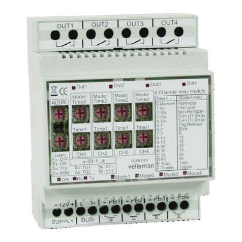
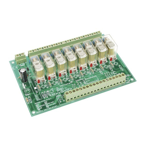
Velleman VMB4RY User manual

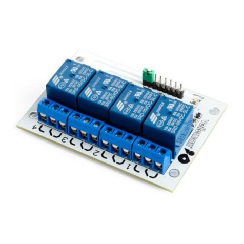
4 Channel Relay module
VMB4RY
4 normal open relay contacts: 5A/230VAC
10 different operation modes : moment control, on/off control, start/
stop timer, staircase lighting timer, non-restartable timer, switch-off
delay, switch-on delay, start timer by releasing push button, timer
with blinking effect, 2-way timer
16 possible time settings : moment - 5s - 10s - 15s - 30s - 1min -
2 min - 5min - 10min - 15min - 30min –1h –2h –5h –1day –on/off
224 possible addresses
required power supply: 12...18VDC
power consumption: 330mA max. (70mA standby).

1 2
5 6 7
Out1 Out2 Out3 Out4
ON Rx Tx Mode1 Mode2 Mode3 Mode4
ADDR.
TGL
ON :ST1
9x
8x ST2:
x=CH1...4
Cx
Dx
Ex
Fx
Learn
:PBM:
OFF:
:
Mode/
Time2 Mode/
Time2 Mode/
Time2 Mode/
Time2
Time1 Time1 Time1 Time1
CH1 CH2 CH3 CH4
velleman
4 Channel relay module
VMB4RY
5'7:5'
5hD:5h
E:1day 1day
F:Toggle Toggle
A:30'
C:2h
B:1h
9:15'
8:10'
30'
2h
1h
15'
10'
1:5s
0:Moment Staircase
Start-stop
Turn Off Delay
Non-Retrigger
Turn On Delay4:30s
6:2'
5:1'
3:15s
2:10s
Trig Release
Blink
Time1 Mode/Time2
TG2
TG1Bx
Ax:
:
PB4
-
12V
-+LHPB2PB1 -PB3- -
8
OUT1 OUT3 OUT4OUT2
A
9
7
6
5
4
3
2
1
0
F
E
D
C
B
8
A
9
7
6
5
4
3
2
1
0
F
E
D
C
B
8
A
9
7
6
5
4
3
2
1
0
F
E
D
C
B
8
A
9
7
6
5
4
3
2
1
0
F
E
D
C
B
8
A
9
7
6
5
4
3
2
1
0
F
E
D
C
B
8
A
9
7
6
5
4
3
2
1
0
F
E
D
C
B
8
A
9
7
6
5
4
3
2
1
0
F
E
D
C
B
8
A
9
7
6
5
4
3
2
1
0
F
E
D
C
B
8
A
9
7
6
5
4
3
2
1
0
F
E
D
C
B
8
A
9
7
6
5
4
3
2
1
0
F
E
D
C
B
BUS
SUPPLY
3 4
8 9 10
26
Out1 Out2 Out3 Out4
ON Rx Tx Mode1 Mode2 Mode3 Mode4
ADDR. CH1 CH2 CH3 CH4
8
A
9
7
6
5
4
3
2
1
0
F
E
D
C
B
8
A
9
7
6
5
4
3
2
1
0
F
E
D
C
B
8
A
9
7
6
5
4
3
2
1
0
F
E
D
C
B
8
A
9
7
6
5
4
3
2
1
0
F
E
D
C
B
8
A
9
7
6
5
4
3
2
1
0
F
E
D
C
B
8
A
9
7
6
5
4
3
2
1
0
F
E
D
C
B
8
A
9
7
6
5
4
3
2
1
0
F
E
D
C
B
8
A
9
7
6
5
4
3
2
1
0
F
E
D
C
B
8
A
9
7
6
5
4
3
2
1
0
F
E
D
C
B
8
A
9
7
6
5
4
3
2
1
0
F
E
D
C
B
25
24
23
15 16 17 18 19 20 21 22
11 12 13 14
27
ADDR. CH1 CH2 CH3 CH4
8
A
9
7
6
5
4
3
2
1
0
F
E
D
C
B
8
A
9
7
6
5
4
3
2
1
0
F
E
D
C
B
8
A
9
7
6
5
4
3
2
1
0
F
E
D
C
B
8
A
9
7
6
5
4
3
2
1
0
F
E
D
C
B
8
A
9
7
6
5
4
3
2
1
0
F
E
D
C
B
8
A
9
7
6
5
4
3
2
1
0
F
E
D
C
B
8
A
9
7
6
5
4
3
2
1
0
F
E
D
C
B
8
A
9
7
6
5
4
3
2
1
0
F
E
D
C
B
8
A
9
7
6
5
4
3
2
1
0
F
E
D
C
B
8
A
9
7
6
5
4
3
2
1
0
F
E
D
C
B
28 29 30 31
32 33 34 35
36
37
2

TIME 1
0 Momentary
1 5s
2 10s
3 15s
4 30s
5 1'
6 2'
7 5'
8 10'
9 15'
A 30'
B 1h
C 2h
D 5h
E 1day
F On/Off
MODE / TIME 2
0 Start-stop timer
1 Staircase timer
2 Non retriggerable timer
3 Turn off delay
4 Turn on delay
5 Trigger on release timer
6 Blinking timer
7 2-way timer (time 2 = 5')
8 2-way timer (time 2 = 10')
9 2-way timer (time 2 = 15')
A 2-way timer (time 2 = 30')
B 2-way timer (time 2 = 1h)
C 2-way timer (time 2 = 2h)
D 2-way timer (time 2 = 5h)
E 2-way timer (time 2 = 1 day)
F 2-way timer (time 2 = On/Off)
3637
ENGLISH
See also connection examples on page 32 & 33 !
Removing the front
28 Operation mode setting channel 1
29 Operation mode setting channel 2
30 Operation mode setting channel 3
31 Operation mode setting channel 4
32 Time setting channel 1
33 Time setting channel 2
34 Time setting channel 3
35 Time setting channel 4
3

4
1 Normal open contact channel 1
2 Normal open contact channel 2
3 Normal open contact channel 3
4 Normal open contact channel 4
5 12V supply
6 Velbus
7 Direct push button control for channel 1
8 Direct push button control for channel 2
9 Direct push button control for channel 3
10 Direct push button control for channel 4
11 Relay-ON indication LED channel 1
12 Relay-ON indication LED channel 2
13 Relay-ON indication LED channel 3
14 Relay-ON indication LED channel 4
15 Power LED
16 Reception LED
17 Forwarding LED
18 Termination
If the module is connected as the final device on the
VELBUS, place the ‘TERM’ jumper. Remove the
jumper in all other cases.
19 Operation mode LED channel 1
20 Operation mode LED channel 2
21 Operation mode LED channel 3
22 Operation mode LED channel 4
Operation mode indication :
The LED will not light if the relay is switched of.
The LED lights if the relay is witched on and the timer is
not activated.
The LED blinks rapidly if the timer is activated.
The LED blinks slowly if the 2nd timer is activated in the
2-way timer mode.
The LED blinks fast if the module is activated in the
‘learning’ mode.
23 Manual control channel 1
24 Manual control channel 2
25 Manual control channel 3
26 Manual control channel 4
27 Adress setting
Enter a unique address (except for ‘81’… '84', ‘91’…
'94', ‘A1’…'A4', ‘B1’ … 'B4', ‘C1’ … 'C4', ‘D1’ … 'D4',
‘E1’ … 'E4' and ‘F1’ … 'F4') for each module.
Establish the module address as ‘00’ if the Velbus will not be
connected (see connection diagram on page 31).

5
Operation mode (page 2&3)
Depending on the setting of this hexadecimal rotary switch, a relay module channel will function as follows:
Remarks: If the rotating switch of the time setting is set on ‘0’, the relay module will always operate in moment control
regardless of the set operation mode. If the rotating switch of the time setting is set on ‘F’, the relay module will operate in
on/off mode.
Start/stop timer : Operating the push button will switch on the relay. After the set time has elapsed, the relay turns off. Operat-
ing the push button when the relay is switched on will immediately switch off the relay.
Staircase lighting timer : Operating the push button will switch on the relay. After the set time has elapsed, the relay will turns
off. Operating the push button when the relay is switched on will restart the timer.
Non-restartable timer : Operating the push button will switch on the relay. After the set time has elapsed, the relay turns off.
Operating the push button when the relay is switched on has no effect.
Switch-off delay : The relay will be switched on as long as the push button is operated. Releasing the push button will start the
timer. After the set time has elapsed, the relay turns off.
Switch-on delay : Operating the push button will start the switch-on delay. The relay will only be switched on after this switch-
on delay has elapsed. Operating the push button when the switch-on delay is running will immediately switch off the switch-on
delay. Operating the push button when the relay is on will immediately switch off the relay.
Start timer with push button release : The relay switches on during the set time by releasing the push button.
Blink timer : Operating the push button will make the relay blink. After the set time has elapsed, the relay turns off. Operating
the push button while the relay is blinking will immediately switch off the relay.
2-way timer : A short press will switch on the relay during the set time 'Time1'. A long press will switch on the relay during the
set time 'Time2'. Operating the push button when the relay is on will immediately switch off the relay.
0
1
2
3
4
5
6
7 - F
36

6
Learning mode:
It is possible to learn up to 15 different push buttons per control group for each channel. Establish the module address as:
ADDRESS
Ch.1 Ch.2 Ch.3 Ch.4
F1 F2 F3 F3 Push buttons switching off the relay
E1 E1 E1 E1 Push buttons switching on the relay
D1 D1 D1 D1 Push buttons switching the relay on or off
C1 C1 C1 C1 Push buttons activating the operation mode
B1 B1 B1 B1 Push buttons starting or stopping the timer
A1 A1 A1 A1 Push buttons starting or stopping the 2nd timer in the 2-way timer mode
91 91 91 91 Push buttons starting or restarting the timer (except in moment control or on-off mode)
81 81 81 81 Push buttons starting or restarting the timer in the 2-way mode (except in on/off mode)
Push buttons to learn for channel control

7
The relay will be switched off and the operation mode LED will blink very rapidly to indicate the learning mode. The push
button LEDs which are saved in the non-volatile memory will also blink very rapidly. In this way it is possible to see which
push buttons for the corresponding group have already been learned.
You can add a specific push button by maintaining it pressed until the relay switches on. When releasing the push button the
relay will switch off and the push button indication LED will blink very rapidly as a confirmation. If this does not work then the
maximum amount of push buttons has been reached.
To delete a learned push button, maintain it pressed. When releasing the push button the indication LED will be turned off.
You can delete all learned push buttons for a specific control group by maintaining the manual control on the relay module
pressed until the relay switches on. When releasing the manual control push button the relay and the indication LEDs of all
corresponding push buttons will turn off.
Quit the learning mode by resetting the relay module’s original address.

1 2
5 6 7
Out1 Out2 Out3 Out4
ON Rx Tx Mode1 Mode2 Mode3 Mode4
ADDR.
TGL
ON :ST1
9x
8x ST2:
x=CH1...4
Cx
Dx
Ex
Fx
Learn
:PBM:
OFF:
:
Mode/
Time2 Mode/
Time2 Mode/
Time2 Mode/
Time2
Time1 Time1 Time1 Time1
CH1 CH2 CH3 CH4
velleman
4 Channel relay module
VMB4RY
5'7:5'
5hD:5h
E:1day 1day
F:Toggle Toggle
A:30'
C:2h
B:1h
9:15'
8:10'
30'
2h
1h
15'
10'
1:5s
0:Moment Staircase
Start-stop
Turn Off Delay
Non-Retrigger
Turn On Delay4:30s
6:2'
5:1'
3:15s
2:10s
Trig Release
Blink
Time1 Mode/Time2
TG2
TG1Bx
Ax:
:
PB4
-
12V
-+LHPB2PB1 -PB3- -
8
OUT1 OUT3 OUT4OUT2
A
9
7
6
5
4
3
2
1
0
F
E
D
C
B
8
A
9
7
6
5
4
3
2
1
0
F
E
D
C
B
8
A
9
7
6
5
4
3
2
1
0
F
E
D
C
B
8
A
9
7
6
5
4
3
2
1
0
F
E
D
C
B
8
A
9
7
6
5
4
3
2
1
0
F
E
D
C
B
8
A
9
7
6
5
4
3
2
1
0
F
E
D
C
B
8
A
9
7
6
5
4
3
2
1
0
F
E
D
C
B
8
A
9
7
6
5
4
3
2
1
0
F
E
D
C
B
8
A
9
7
6
5
4
3
2
1
0
F
E
D
C
B
8
A
9
7
6
5
4
3
2
1
0
F
E
D
C
B
BUS
SUPPLY
3 4
8 9 10
26
Out1 Out2 Out3 Out4
ON Rx Tx Mode1 Mode2 Mode3 Mode4
ADDR. CH1 CH2 CH3 CH4
8
A
9
7
6
5
4
3
2
1
0
F
E
D
C
B
8
A
9
7
6
5
4
3
2
1
0
F
E
D
C
B
8
A
9
7
6
5
4
3
2
1
0
F
E
D
C
B
8
A
9
7
6
5
4
3
2
1
0
F
E
D
C
B
8
A
9
7
6
5
4
3
2
1
0
F
E
D
C
B
8
A
9
7
6
5
4
3
2
1
0
F
E
D
C
B
8
A
9
7
6
5
4
3
2
1
0
F
E
D
C
B
8
A
9
7
6
5
4
3
2
1
0
F
E
D
C
B
8
A
9
7
6
5
4
3
2
1
0
F
E
D
C
B
8
A
9
7
6
5
4
3
2
1
0
F
E
D
C
B
25
24
23
15 16 17 18 19 20 21 22
11 12 13 14
27
ADDR. CH1 CH2 CH3 CH4
8
A
9
7
6
5
4
3
2
1
0
F
E
D
C
B
8
A
9
7
6
5
4
3
2
1
0
F
E
D
C
B
8
A
9
7
6
5
4
3
2
1
0
F
E
D
C
B
8
A
9
7
6
5
4
3
2
1
0
F
E
D
C
B
8
A
9
7
6
5
4
3
2
1
0
F
E
D
C
B
8
A
9
7
6
5
4
3
2
1
0
F
E
D
C
B
8
A
9
7
6
5
4
3
2
1
0
F
E
D
C
B
8
A
9
7
6
5
4
3
2
1
0
F
E
D
C
B
8
A
9
7
6
5
4
3
2
1
0
F
E
D
C
B
8
A
9
7
6
5
4
3
2
1
0
F
E
D
C
B
28 29 30 31
32 33 34 35
36
37
8

Deksel verwijderen
NEDERLANDS
3637
Zie aansluitingsvoorbeelden pag. 32 en 33 !
28 Werkingsmodeïnstelling kanaal 1
29 Werkingsmodeïnstelling kanaal 2
30 Werkingsmodeïnstelling kanaal 3
31 Werkingsmodeïnstelling kanaal 4
32 Tijdsinstelling kanaal 1
33 Tijdsinstelling kanaal 2
34 Tijdsinstelling kanaal 3
35 Tijdsinstelling kanaal 4
TIME 1
0 Momentbediening
1 5s
2 10s
3 15s
4 30s
5 1'
6 2'
7 5'
8 10'
9 15'
A 30'
B 1h
C 2h
D 5h
E 1dag
F Aan / Uit
MODE / TIME2
0 Start / stop timer
1 Trappenhuisautomaat
2 Niet-herstartbare timer
3 Uitschakelvertraging
4 Inschakelvertraging
5 Timer starten bij loslaten drukknop
6 Knipper timer
7 2-tijdentimer (timer2 = 5')
8 2-tijdentimer (timer2 = 10')
9 2-tijdentimer (timer2 = 15')
A 2-tijdentimer (timer2 = 30')
B 2-tijdentimer (timer2 = 1h)
C 2-tijdentimer (timer2 = 2h)
D 2-tijdentimer (timer2 = 5h)
E 2-tijdentimer (timer2 = 1 dag)
F 2-tijdentimer (timer2 = Aan / Uit)
9

10
1 Normaal open contact kanaal 1
2 Normaal open contact kanaal 2
3 Normaal open contact kanaal 3
4 Normaal open contact kanaal 4
5 12V voeding
6 Velbus
7 Directe drukknopbediening voor kanaal 1
8 Directe drukknopbediening voor kanaal 2
9 Directe drukknopbediening voor kanaal 3
10 Directe drukknopbediening voor kanaal 4
11 Relais aan indicatie-LED kanaal 1
12 Relais aan indicatie-LED kanaal 2
13 Relais aan indicatie-LED kanaal 3
14 Relais aan indicatie-LED kanaal 4
15 Voedings-LED
16 Ontvangst-LED
17 Zend-LED
18 Afsluiting :
Indien de module als laatste op de VELBUS is
aangesloten moet de ‘TERM’ jumper geplaatst worden.
In alle andere gevallen moet deze verwijderd worden.
19 Werkingsmode-LED kanaal 1
20 Werkingsmode-LED kanaal 2
21 Werkingsmode-LED kanaal 3
22 Werkingsmode-LED kanaal 4
Mode LED :
De LED brandt niet indien het relais uitgeschakeld is.
De LED brandt indien het relais ingeschakeld is en de
timer niet geactiveerd is.
De LED knippert snel indien de timer geactiveerd is.
De LED knippert traag indien de tweede timer
geactiveerd is bij de 2-tijden timermode.
De LED knippert zeer snel indien de module in de
leermode staat.
23 Manuele bediening kanaal 1
24 Manuele bediening kanaal 2
25 Manuele bediening kanaal 3
26 Manuele bediening kanaal 4
27 Adressering
Stel een uniek adres in voor elke module (uitgezonderd
‘81’...’84’, ‘91’...’94’, ‘A1’...’A4’, ‘B1’...’B4’, ‘C1’...’C4’,
‘D1’...’D4’, ‘E1’...’E4’ en ‘F1’...’F4’).
Als de velbus niet aangesloten wordt (zie aansluitschema
pag. 31), stel dan het adres van de module in op ‘00’.

11
Start/stop timer : Bedienen van de drukknop schakelt het relais in. Nadat de ingestelde tijd verlopen is, schakelt het relais uit.
Bedienen van de drukknop wanneer het relais aan is, zal het relais onmiddellijk uitschakelen.
Trappenhuisautomaat : Bedienen van de drukknop schakelt het relais in. Nadat de ingestelde tijd verlopen is, schakelt het
relais uit. Bedienen van de drukknop wanneer het relais aan is, herstart de timer.
Niet-herstartbare timer : Bedienen van de drukknop schakelt het relais in. Nadat de ingestelde tijd verlopen is, schakelt het
relais uit. Bedienen van de drukknop wanneer het relais aan is, heeft geen enkel effect.
Uitschakelvertraging : Zolang de drukknop bediend wordt, zal het relais ingeschakeld worden. Bij het loslaten van de
drukknop wordt de timer gestart. Nadat de ingestelde tijd verlopen is, schakelt het relais uit.
Inschakelvertraging : Bij bedienen van de drukknop wordt de inschakelvertraging gestart. Het relais wordt pas ingeschakeld
nadat deze inschakeltijd verlopen is. Bedienen van de drukknop wanneer de inschakelvertraging loopt, zal de
inschakelvertraging onmiddellijk uitschakelen. Bedienen van de drukknop wanneer het relais aan is, zal het relais onmiddellijk
uitschakelen.
Timer starten bij loslaten drukknop : Het relais schakelt in gedurende de ingestelde tijd bij het loslaten van de drukknop.
Knippertimer : Bedienen van de drukknop zal het relais laten knipperen. Nadat de ingestelde tijd verlopen is, schakelt het
relais uit. Bedienen van de drukknop tijdens het knipperen van het relais, zal het relais onmiddellijk uitschakelen
2-tijdentimer : Kort drukken zal het relais inschakelen gedurende de ingestelde tijd ‘Time1’, lang drukken zal het relais
inschakelen gedurende de ingestelde tijd ‘Time2'. Bedienen van de drukknop wanneer het relais aan is, zal het relais
onmiddellijk uitschakelen.
0
1
2
3
4
5
6
7 - F
Werkingsmode (zie bladzijde 8&9)
Afhankelijk van de instelling van deze hexadecimale draaischakelaar zal een kanaal van de relaismodule als volgt functioneren:
36
Opmerkingen: Indien de tijdsinstelling op ‘0’ staat, zal de relaismodule steeds in momentbediening werken ongeacht de
ingestelde werkingsmode. Indien de tijdsinstelling op ‘F’ staat, zal de relaismodule in aan/uit mode werken.

12
Leermode:
Voor elk kanaal kunnen er tot 15 verschillende drukknoppen aangeleerd worden per bedieningsgroep. Stel het adres van de
module in op:
ADRES
Kanaal
1Kanaal
2Kanaal
3Kanaal
4
F1 F2 F3 F3 die het relais uitschakelen
E1 E1 E1 E1 die het relais inschakelen
D1 D1 D1 D1 die het relais in- of uitschakelen
C1 C1 C1 C1 die de ingestelde mode activeren
B1 B1 B1 B1 die de timer starten of stoppen
A1 A1 A1 A1 die de tweede timer starten of stoppen inde 2-tijden timermode
91 91 91 91 die de timer starten of herstarten (behalve bij momentbediening of aan/uit mode)
81 81 81 81 die de tweede timer starten of herstarten in de 2-tijden timermode (behalve bij aan/uit mode)
Aan te leren drukknoppen voor bediening van een kanaal

13
De relais worden uitgeschakeld en de werkingsmode-LED van het betreffende kanaal zal nu zeer snel knipperen ter indicatie
van de leermode. De LEDs van de drukknoppen die reeds opgeslagen zijn in het niet-vluchtige geheugen zullen ook snel
knipperen. Op die manier kan men gemakkelijk zien welke drukknoppen voor de betreffende groep reeds aangeleerd zijn.
Men kan een bepaalde drukknop toevoegen door deze lang in te drukken totdat het relais inschakelt. Bij het loslaten van de
drukknop zal het relais uitschakelen en de indicatie-LED van de drukknop zeer snel knipperen ter bevestiging. Lukt dit niet, dan
is het maximum aantal aan te leren drukknoppen bereikt.
Een aangeleerde drukknop verwijderen gebeurt door deze lang in te drukken. Bij het loslaten van de drukknop zal de indicatie-
LED van de drukknop gedoofd zijn.
Men kan alle aangeleerde drukknoppen voor een bepaalde bedieningsgroep verwijderen door de manuele bediening van het
betreffende kanaal op de relaismodule lang in te drukken tot het relais inschakelt. Bij het loslaten van de manuele
bedieningsdrukknop zal het relais uitschakelen en de indicatie-LEDs van alle bijbehorende drukknoppen doven.
Verlaat de leermode door het adres van de relaismodule terug op zijn oorspronkelijke waarde te plaatsen.

1 2
5 6 7
Out1 Out2 Out3 Out4
ON Rx Tx Mode1 Mode2 Mode3 Mode4
ADDR.
TGL
ON :ST1
9x
8x ST2:
x=CH1...4
Cx
Dx
Ex
Fx
Learn
:PBM:
OFF:
:
Mode/
Time2 Mode/
Time2 Mode/
Time2 Mode/
Time2
Time1 Time1 Time1 Time1
CH1 CH2 CH3 CH4
velleman
4 Channel relay module
VMB4RY
5'7:5'
5hD:5h
E:1day 1day
F:Toggle Toggle
A:30'
C:2h
B:1h
9:15'
8:10'
30'
2h
1h
15'
10'
1:5s
0:Moment Staircase
Start-stop
Turn Off Delay
Non-Retrigger
Turn On Delay4:30s
6:2'
5:1'
3:15s
2:10s
Trig Release
Blink
Time1 Mode/Time2
TG2
TG1Bx
Ax:
:
PB4
-
12V
-+LHPB2PB1 -PB3- -
8
OUT1 OUT3 OUT4OUT2
A
9
7
6
5
4
3
2
1
0
F
E
D
C
B
8
A
9
7
6
5
4
3
2
1
0
F
E
D
C
B
8
A
9
7
6
5
4
3
2
1
0
F
E
D
C
B
8
A
9
7
6
5
4
3
2
1
0
F
E
D
C
B
8
A
9
7
6
5
4
3
2
1
0
F
E
D
C
B
8
A
9
7
6
5
4
3
2
1
0
F
E
D
C
B
8
A
9
7
6
5
4
3
2
1
0
F
E
D
C
B
8
A
9
7
6
5
4
3
2
1
0
F
E
D
C
B
8
A
9
7
6
5
4
3
2
1
0
F
E
D
C
B
8
A
9
7
6
5
4
3
2
1
0
F
E
D
C
B
BUS
SUPPLY
3 4
8 9 10
26
Out1 Out2 Out3 Out4
ON Rx Tx Mode1 Mode2 Mode3 Mode4
ADDR. CH1 CH2 CH3 CH4
8
A
9
7
6
5
4
3
2
1
0
F
E
D
C
B
8
A
9
7
6
5
4
3
2
1
0
F
E
D
C
B
8
A
9
7
6
5
4
3
2
1
0
F
E
D
C
B
8
A
9
7
6
5
4
3
2
1
0
F
E
D
C
B
8
A
9
7
6
5
4
3
2
1
0
F
E
D
C
B
8
A
9
7
6
5
4
3
2
1
0
F
E
D
C
B
8
A
9
7
6
5
4
3
2
1
0
F
E
D
C
B
8
A
9
7
6
5
4
3
2
1
0
F
E
D
C
B
8
A
9
7
6
5
4
3
2
1
0
F
E
D
C
B
8
A
9
7
6
5
4
3
2
1
0
F
E
D
C
B
25
24
23
15 16 17 18 19 20 21 22
11 12 13 14
27
ADDR. CH1 CH2 CH3 CH4
8
A
9
7
6
5
4
3
2
1
0
F
E
D
C
B
8
A
9
7
6
5
4
3
2
1
0
F
E
D
C
B
8
A
9
7
6
5
4
3
2
1
0
F
E
D
C
B
8
A
9
7
6
5
4
3
2
1
0
F
E
D
C
B
8
A
9
7
6
5
4
3
2
1
0
F
E
D
C
B
8
A
9
7
6
5
4
3
2
1
0
F
E
D
C
B
8
A
9
7
6
5
4
3
2
1
0
F
E
D
C
B
8
A
9
7
6
5
4
3
2
1
0
F
E
D
C
B
8
A
9
7
6
5
4
3
2
1
0
F
E
D
C
B
8
A
9
7
6
5
4
3
2
1
0
F
E
D
C
B
28 29 30 31
32 33 34 35
36
37
14

Retirez le couvercle
FRANCAIS
36
37
Voir également l'examples de connextion à la page 32 et 33!
28 Réglage mode d’opération canal 1
29 Réglage mode d’opération canal 2
30 Réglage mode d’opération canal 3
31 Réglage mode d’opération canal 4
32 Réglage de délai canal 1
33 Réglage de délai canal 2
34 Réglage de délai canal 3
35 Réglage de délai canal 4
15
TIME 1
0 Contrôle
momentané
1 5s
2 10s
3 15s
4 30s
5 1'
6 2'
7 5'
8 10'
9 15'
A 30'
B 1h
C 2h
D 5h
E 1jour
F Marche /
arrêt
MODE / TIME 2
0 Minuteur marche/arrêt
1 Temporisateur de cage d’escalier
2 Minuteur non-réinitialisable
3 Délai de coupure
4 Temporisation de déclenchement
5 Enclenchement du minuteur en relâchant le
bouton poussoir
6 Minuteuravec effet de clignotement
7 Minuteurà 2 temps (délai2 = 5')
8 Minuteur à 2 temps (délai2 = 10')
9 Minuteur à 2 temps (délai2 = 15')
A Minuteur à 2 temps (délai2 = 30')
B Minuteur à 2 temps (délai2 = 1h)
C Minuteur à 2 temps (délai2 = 2h)
D Minuteur à 2 temps (délai2 = 5h)
E Minuteur à 2 temps (délai2 = 1jour)
F Minuteur à 2 temps (délai2 = Marche / arrêt)

16
1 Contact normal ouvert canal 1
2 Contact normal ouvert canal 2
3 Contact normal ouvert canal 3
4 Contact normal ouvert canal 4
5 Alimentation 12V
6 Velbus
7 Contrôle direct des boutons poussoirs canal 1
8 Contrôle direct des boutons poussoirs canal 2
9 Contrôle direct des boutons poussoirs canal 3
10 Contrôle direct des boutons poussoirs canal 4
11 Voyant LED relais enclenché canal 1
12 Voyant LED relais enclenché canal 2
13 Voyant LED relais enclenché canal 3
14 Voyant LED relais enclenché canal 4
15 LED d’alimentation
16 LED de réception
17 LED de transfert
18 Terminaison
Si le module est connecté en dernier dans la série
VELBUS, il faut placer le pontage ‘TERM’. Retirez-le
si ceci n’est pas le cas.
19 LED mode d’opération canal 1
20 LED mode d’opération canal 2
21 LED mode d’opération canal 3
22 LED mode d’opération canal 4
LED mode d’opération :
La LED ne s’allume pas si le relais est coupé.
La LED s’allume si le relais est enclenché et le minuteur
n’est pas activé.
La LED clignote rapidement si le minuteur est activé.
La LED clignote lentement si le second minuteur est
activé dans le mode à 2 temps.
La LED clignote rapidement si le minuteur est en mode
d’apprentissage
23 Contrôle manuel canal 1
24 Contrôle manuel canal 2
25 Contrôle manuel canal 3
26 Contrôle manuel canal 4
27 Adressage
Attribuez une adresse unique (excepté ‘81’...’84’,
‘91’...’94’, ‘A1’...’A4’, ‘B1’...’B4’, ‘C1’...’C4’,
‘D1’...’D4’, ‘E1’...’E4’ et ‘F1’...’F4’) pour chaque module
Établissez l’adresse du module sur « 00 » au cas où le Velbus
n’est pas connecté (voir schéma de connexion page 31).

17
Mode d’opération (page 14&15)
Selon le réglage de cet interrupteur rotatif hexadécimal le canal du module relais fonctionnera comme suit :
36
Remarque: Si l’interrupteur rotatif du réglage de délai est positionné sur ‘0’ le module relais fonctionnera toujours en
contrôle momentané, quel que soit le mode d’opération. Si l’interrupteur rotatif de délai est positionné sur ‘F’, le module
relais fonctionnera en mode marche/arrêt.
Minuteur marche/arrêt : L’actionnement du bouton poussoir enclenchera le relais. Le relais se coupe après l’écoulement du délai
introduit. L’actionnement du bouton poussoir lorsque le relais est enclenché, coupera le relais instantanément.
Temporisateur de cage d’escalier : L’actionnement du bouton poussoir enclenchera le relais. Le relais se coupeaprès l’écoulement
du délai introduit. L’actionnement du bouton poussoir lorsque le relais est enclenché, redémarrera le minuteur.
Minuteur non-réinitialisable : L’actionnement du bouton poussoir enclenchera le relais. Le relais se coupe après
l’écoulement du délai introduit. L’actionnement du bouton poussoir lorsque le relais est enclenché, n’a aucun effet.
Délai de coupure : Le relais restera enclenché aussi longtemps que le bouton poussoir est actionné. Le minuteur démarre dès
le relâchement du bouton poussoir. Le relais se coupe après l’écoulement du délai introduit.
Temporisation de déclenchement : L’actionnement du bouton poussoir démarrera le délai de coupure. Le relais ne sera
enclenché qu’après l’écoulement de ce délai de coupure. L’actionnement du bouton poussoir lorsque le délai de coupure est
s’écoule, coupera instantanément le délai de coupure. L’actionnement du bouton poussoir lorsque le relais est enclenché,
coupera instantanément le relais.
Enclenchement du minuteur en relâchant le bouton poussoir : Le relais s’enclenche pendant le délai introduit en relâchant
le bouton poussoir.
Minuteur avec effet de clignotement : L’actionnement du bouton poussoir fera clignoter le relais. Le relais se coupe après
l’écoulement du délai introduit. L’actionnement du bouton poussoir lorsque le relais clignote, coupera instantanément le relais.
Minuteur à 2 temps : Une brève pression enclenchera le relais pendant le délai introduit ‘Time1’, une pression longue
enclenchera le relais pendant le délai introduit ‘Time2’. Un actionnement du bouton poussoir alors que le relais est enclenché,
déclenchera immédiatement ce relais.
0
1
2
3
4
5
6
7 - F

18
Mode d’apprentissage:
Il est possible d’apprendre jusqu’à 15 boutons poussoirs par groupe de contrôle pour chaque canal. Établissez l’adresse du
module comme suit :
ADRESSE
canal
1Canal
2Canal
3Canal
4
F1 F2 F3 F3 Coupant le relais
E1 E1 E1 E1 Enclenchant le relais
D1 D1 D1 D1 Enclenchant ou coupant le relais
C1 C1 C1 C1 Activant le mode d’opération introduit
B1 B1 B1 B1 Démarrant ou arrêtant le minuteur
A1 A1 A1 A1 Démarrant or arrêtant le second minuteur en mode minuteur à 2 temps
91 91 91 91 Démarrant ou redémarrant le minuteur (excepté en contrôle momentané ou en mode marche/arrêt)
81 81 81 81 Démarrant ou redémarrant le second minuteur en mode minuteur à 2 temps (excepté en mode marche/
arrêt)
MODE (Boutons poussoirs à apprendre)

19
Le relais sera coupé et la LED du mode d’opération clignotera très rapidement pour indiquer le mode d’apprentissage. Les LEDs
des boutons poussoirs qui sont sauvegardés dans la mémoire non-volatile clignoteront également très rapidement. De cette
manière il est facile de voir quels boutons poussoirs du groupe correspondant ont déjà été appris.
Il est possible d’ajouter un bouton poussoir spécifique en le maintenant enfoncé jusqu’à ce que le relais s’enclenche. En
relâchant le bouton poussoir le relais se coupera et le voyant LED du bouton poussoir clignotera très rapidement en guise de
confirmation. S’il est impossible d’ajouter un bouton poussoir, le nombre maximum a été atteint.
Maintenez enfoncé un bouton poussoir appris pour l’effacer. En le relâchant, le voyant LED de celui-ci s’éteindra.
Effacez tous les boutons poussoirs appris pour un groupe de contrôle spécifique en maintenant enfoncé le contrôle manuel sur le
module relais jusqu’à ce que le relais se coupe. En relâchant le bouton de contrôle manuel l’ampoule et les voyants LED de tous
les boutons poussoirs correspondants s’éteindront.
Quittez le mode d’apprentissage en repositionnant l’adresse du module variateur sur la valeur d’origine.

1 2
5 6 7
Out1 Out2 Out3 Out4
ON Rx Tx Mode1 Mode2 Mode3 Mode4
ADDR.
TGL
ON :ST1
9x
8x ST2:
x=CH1...4
Cx
Dx
Ex
Fx
Learn
:PBM:
OFF:
:
Mode/
Time2 Mode/
Time2 Mode/
Time2 Mode/
Time2
Time1 Time1 Time1 Time1
CH1 CH2 CH3 CH4
velleman
4 Channel relay module
VMB4RY
5'7:5'
5hD:5h
E:1day 1day
F:Toggle Toggle
A:30'
C:2h
B:1h
9:15'
8:10'
30'
2h
1h
15'
10'
1:5s
0:Moment Staircase
Start-stop
Turn Off Delay
Non-Retrigger
Turn On Delay4:30s
6:2'
5:1'
3:15s
2:10s
Trig Release
Blink
Time1 Mode/Time2
TG2
TG1Bx
Ax:
:
PB4
-
12V
-+LHPB2PB1 -PB3- -
8
OUT1 OUT3 OUT4OUT2
A
9
7
6
5
4
3
2
1
0
F
E
D
C
B
8
A
9
7
6
5
4
3
2
1
0
F
E
D
C
B
8
A
9
7
6
5
4
3
2
1
0
F
E
D
C
B
8
A
9
7
6
5
4
3
2
1
0
F
E
D
C
B
8
A
9
7
6
5
4
3
2
1
0
F
E
D
C
B
8
A
9
7
6
5
4
3
2
1
0
F
E
D
C
B
8
A
9
7
6
5
4
3
2
1
0
F
E
D
C
B
8
A
9
7
6
5
4
3
2
1
0
F
E
D
C
B
8
A
9
7
6
5
4
3
2
1
0
F
E
D
C
B
8
A
9
7
6
5
4
3
2
1
0
F
E
D
C
B
BUS
SUPPLY
3 4
8 9 10
26
Out1 Out2 Out3 Out4
ON Rx Tx Mode1 Mode2 Mode3 Mode4
ADDR. CH1 CH2 CH3 CH4
8
A
9
7
6
5
4
3
2
1
0
F
E
D
C
B
8
A
9
7
6
5
4
3
2
1
0
F
E
D
C
B
8
A
9
7
6
5
4
3
2
1
0
F
E
D
C
B
8
A
9
7
6
5
4
3
2
1
0
F
E
D
C
B
8
A
9
7
6
5
4
3
2
1
0
F
E
D
C
B
8
A
9
7
6
5
4
3
2
1
0
F
E
D
C
B
8
A
9
7
6
5
4
3
2
1
0
F
E
D
C
B
8
A
9
7
6
5
4
3
2
1
0
F
E
D
C
B
8
A
9
7
6
5
4
3
2
1
0
F
E
D
C
B
8
A
9
7
6
5
4
3
2
1
0
F
E
D
C
B
25
24
23
15 16 17 18 19 20 21 22
11 12 13 14
27
ADDR. CH1 CH2 CH3 CH4
8
A
9
7
6
5
4
3
2
1
0
F
E
D
C
B
8
A
9
7
6
5
4
3
2
1
0
F
E
D
C
B
8
A
9
7
6
5
4
3
2
1
0
F
E
D
C
B
8
A
9
7
6
5
4
3
2
1
0
F
E
D
C
B
8
A
9
7
6
5
4
3
2
1
0
F
E
D
C
B
8
A
9
7
6
5
4
3
2
1
0
F
E
D
C
B
8
A
9
7
6
5
4
3
2
1
0
F
E
D
C
B
8
A
9
7
6
5
4
3
2
1
0
F
E
D
C
B
8
A
9
7
6
5
4
3
2
1
0
F
E
D
C
B
8
A
9
7
6
5
4
3
2
1
0
F
E
D
C
B
28 29 30 31
32 33 34 35
36
37
20
Other manuals for VMB4RY
2
Table of contents
Languages:
Other Velleman Relay manuals

Velleman
Velleman VM129 User manual

Velleman
Velleman VMA332 User manual

Velleman
Velleman VMA400 User manual

Velleman
Velleman VM116 User manual

Velleman
Velleman K8056 User manual

Velleman
Velleman VMB4RY User manual

Velleman
Velleman VMA331 User manual

Velleman
Velleman Velbus VMB1RY User manual

Velleman
Velleman K6714 User manual
Popular Relay manuals by other brands

Schweitzer Engineering Laboratories
Schweitzer Engineering Laboratories SEL-501-2 instruction manual

GE
GE UR series Release notes

Siemens
Siemens 3VT9115-5GY31 operating instructions

Eaton
Eaton ES4A-221-DMX-SIM installation instructions

GMI
GMI D5295S instruction manual

DMX4ALL
DMX4ALL DMX-RELAIS 8 INRUSH+ user manual