Venini VCG60S User manual

COOKTOP
VCG60S

Congratulaons on purchasing your new Venini product.
It is important that you read through the following use and care manual
thoroughly to familiarize yourself with the installaon and operaon
requirements of your appliance to ensure opmum performance.
Our Customer Care centre is there to ensure you get the most out of
your appliance.
For any aer sales service please contact our
Customer Care team
on
1800 444 357
or email
and one of our Customer Care Team will get back to you.
Venini is a division of Home Appliances PTY LTD
20 Carloa Street Artarmon 2064
Sales
1800 805 300
Service
1800 444 357
Website
www.venini.com.au

3
Contents
Enviro
nmental note 4
Important safety information 5 – 7
Specifications 8 – 9
Electrical details 9
Gas details 9
Gas hob surface layout 9
Using t e gas ob 10 - 11
Before first use 10
Switchin the hob on 10
Ener y savin tips 11
Cleaning 12 - 13
Cleanin the hob top 12
After each use 12
Cleanin the hob burners 12
Maintainin the enamelled pan stands 13
Installation 13 - 25
Positionin 14
Unpackin the appliance 14
Installin the appliance 15 – 16
Gas connection 17
Ventilation requirements 18
Gas Safety (Installation and Use) Re ulations 19
Gas Adjustment (Conversion to LPG) 20
Minimum flow adjustment for hob as taps 21
Gas tap maintenance 22
Safety warnin s 23
Electrical connection 24
Replacin the mains supply cable 24-25
My appliance isn’t working correctly 26
Contact details 28

4
Environmental note
o The packa in materials that the manufacturer uses are
environmentally friendly and can be recycled.
o Please discard all packa in material with due re ard for the
environment.

5
Important safety information
Your safety is of the utmost importance to the
manufacturer. Please make sure that you read this
instruction booklet before attemptin to install or use
the appliance. If you are unsure of any of the
information contained in this booklet, please contact the
Retailer where you purchased your unit from.
General Information
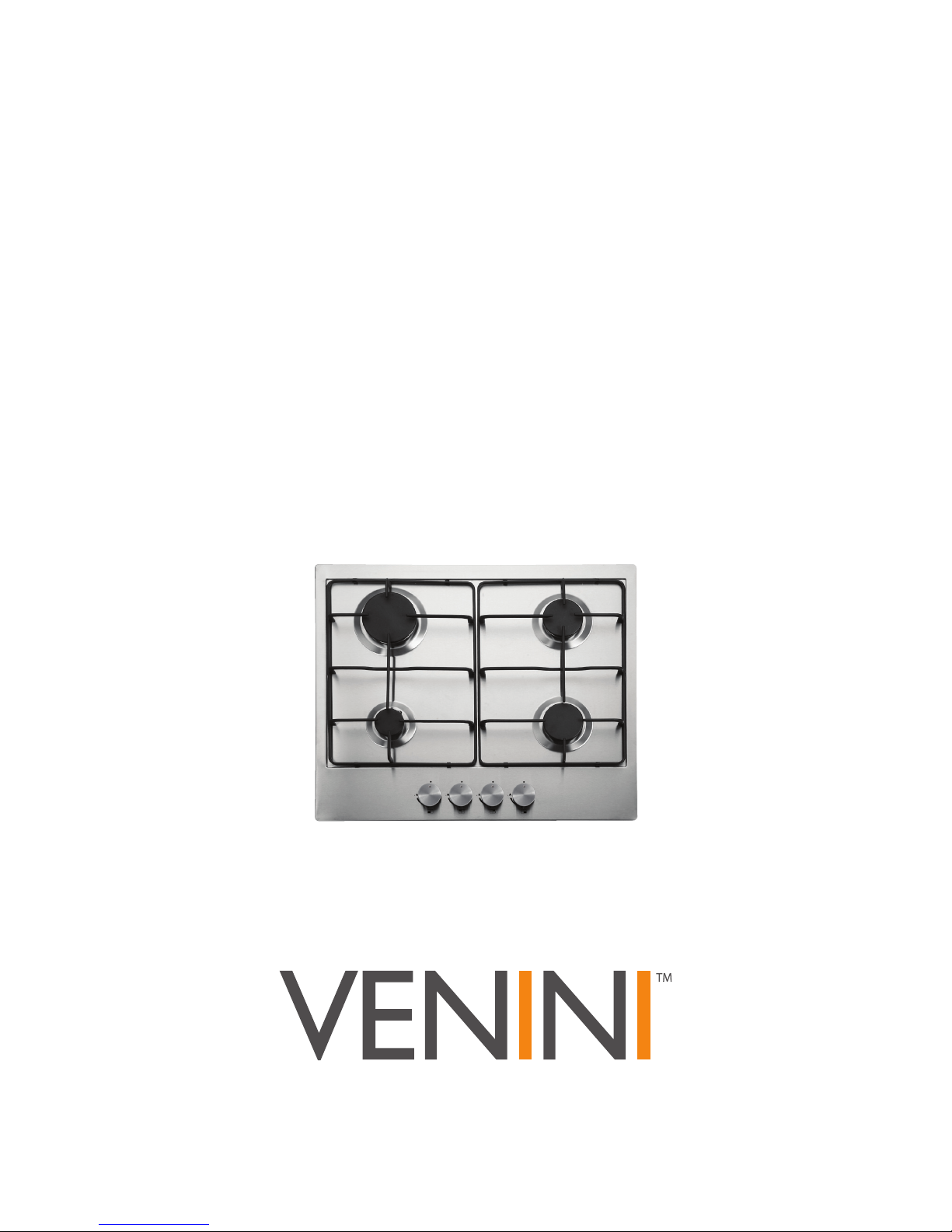
o This appliance is desi ned for domestic household use and for
the cookin and fryin of domestic foodstuffs.
o IMPORTANT: The adjacent furniture and all materials used in
the installation must be able to withstand a minimum
temperature of 85°C above the ambient temperature of the
room it is located in, whilst in use.
o Certain types of vinyl or laminate kitchen furniture are
particularly prone to heat dama e or discolouration at
temperatures below the uidelines iven above.
o Any dama e caused by the appliance bein installed in
contravention of this temperature limit, will be the liability of
the owner
o Your new appliance is uaranteed a ainst electrical or
mechanical defects, subject to certain exclusions that are noted
in the Conditions of Guarantee. The fore oin does not affect
your statutory ri hts.
o The use of this appliance for any other purpose or in any other
environment without the express a reement of the manufacturer
Ltd. will invalidate any warranty or liability claim.
o You should not use this appliance to store items on or as a work
surface.
o No modifications to the appliance are permitted by the
manufacturer.
o You should not store or place flammable or hi hly flammable
liquids/materials on top of or near the appliance. Items made
from aluminium, plastic or plastic film should also be kept away
from the appliance, as they may fuse to the surface.
o Repairs may only be carried out by authorised service
agents

6
C ild Safety
o The manufacturer stron ly recommends that babies and youn
children are prevented from bein near to the appliance and not
allowed to touch the appliance at any time Durin and after
use, all surfaces will be hot.
o If it is necessary for youn er family members to be in the
kitchen, please ensure that they are kept under close supervision
at all times.
o Older children should only be allowed to utilise the appliance
when supervised.
General Safety
o The appliance should only be installed and connected by a
suitably qualified person.
o Care should be taken to ensure that the units and work surfaces
that you build the appliance into, meet with the relevant
standards.
During use
o Any film or stickers that are present on the hob surface when it
is delivered should be removed before use.
o Care should be used when utilisin the appliance, otherwise
there is a risk of burns bein caused.
o You should not allow the electrical connection cables to come
into contact with the hob surface when it is hot or any hot
cookware.
o If fat and oil overheats, then it can i nite extremely quickly. For
this reason, when cookin with fat and oil the appliance should
not be left unattended.
o Make sure that all of the cookin zones are switched off after use.

7
Cleaning
o Cleanin of the hob should be carried out on a re ular basis.
o IMPORTANT: Before attempting to clean the appliance, it
should be disconnected from the mains and cool.
o Great care should be taken whilst usin this appliance and when
followin the cleanin procedure.
o You should not use a steam jet or any other hi h pressure
cleanin equipment to clean the appliance.
Installation
This appliance must be correctly installed by a
suitably qualified person, strictly in accordance
with the manufacturer’s instructions Please see
the specific section of this booklet that refers to
installation
o The manufacturer declines any responsibility for injury or
damage, to person or property, as a result of improper
use or installation of this appliance
o The manufacturer DOES NOT recommend that this
appliance is installed on any type of marine vessel
Declaration of conformity
This appliance complies with the followin European Directives:
-2006/95/CE General Re ulations / Low tension
-2009/142/CE Concernin as appliances
-1935/2004/CE 90/128/EEC this appliance is suitable to come in
contact with food
-2004/108/CE Electroma netic compatibility
-Gas products – AS4551
-Low volta e – 73/23
-Safety standards – EN 60335-1, EN30-1-1, AS/NZS 3350-1,3350-2-6
The manufacturer declares that the hob is built usin certified
materials and requires the appliance to be installed in accordance with
the standards currently in force. This appliance must be used by a
trained person for domestic purposes only.

8
Specifications
Product dimensions: Aperture dimensions:
Depth: 510 mm Depth: 480 mm
Width: 600 mm Width: 560 mm
Hei ht: 40 mm
Product specifications:
o 1 x 10.8 MJ/h rapid burner
o 2 x 6.3 MJ/h semi-rapid burners
o 1 x 3.6 MJ/h auxiliary burner
o Front control operation
o Automatic i nition
o Enamelled pan stands
Standard accessories:
o LPG conversion jets
o Re ulator

9
Gas ob surface layout
ACG6S
A = 10.8 MJ/h rapid burner
B = 6.3 MJ/h semi-rapid burners
C = 3.6 MJ/h auxiliary burner
D = Control panel
Electrical details
Rated Voltage: 220 - 240 Vac 50 / 60 Hz
Supply Connection: 3A
Max Rated Inputs: 0.0008 kW
Mains Supply Lead: 3 core x 0.75mm² (Type RR-F <HAR> marked)
Gas details
Connection: Rp ½ (ISO R7)
Type: Natural Gas (1.0 KPa)
ULPG (2.75 KPa)
For future reference please record the followin information which can
be found on the ratin plate and the date of purchase which can be
found on your sales invoice. The ratin plate of your hob is located on
the underneath of the appliance. Therefore it is a ood idea to record
this information before you install your appliance.
Model Number ……………………………….
Serial Number ……………………………….
Date of Purchase ……………………………….

10
Using t e gas ob
Before first use
IMPORTANT: You should clean the hob surface
see “Cleaning and maintenance” section).
Switc ing t e ob on
The followin symbols will appear on the control panel, next to each
control knob:
= as off
Lar e flame: maximum settin
Small flame: minimum settin
o The minimum settin is at the end of the anti-clockwise rotation of
the control knob.
o All operation positions must be selected between the maximum and
minimum position.
o Never select a knob position between the maximum and off
position.
o The symbol on the control panel next to the control knob
will indicate which as burner it operates.
To i nite a burner:
o Press in the control knob of the burner that you wish to li ht and
turn it anti-clockwise to the maximum position.
o If you keep the control knob depressed, the automatic i nition
for the burner will operate.
o You should hold down the control knob for 20 seconds after the
flame on the burner has lit.
o After this 20 second interval, turn the control knob to your
required settin between the maximum and minimum settin
symbols.
o To switch the burner off, turn the control knob fully clockwise to
the as off position.

11
o In case of power failure, the burners can be lit by carefully usin
a match.
Energy saving tips
BURNERS
PANS
Minimum
diameter
Maximum
diameter
Wok
220 mm
260 mm
Rapid 180 mm 220 mm
Semi
-
rapid
120 mm
200 mm
Auxiliary
80 mm
160 mm
o The diameter of the bottom of the pan should correspond to that
of the burner.
o The burner flame must never extend beyond the diameter of the
pan.
o Use flat bottomed pans only.
o When possible, keep a lid on the pan whilst cookin .
o Cook ve etables with as little water as possible, to reduce
cookin times.
IMPORTANT: Always place pans centrally over the hob burners and
position them so that the handles cannot get accidentally caught or
knocked off. You should also make sure that the handle is not over one
of the other hob burner flames.

12
Cleaning
Cleaning operations must only be carried out when
the hob is cool
The appliance should be disconnected from your
mains supply before commencing any cleaning
process
Cleaning t e ob top
Any residues that are left on the hob top surface from cleanin
a ents will dama e it. You should remove any residues with
warm soapy water.
Abrasive cleaners or sharp objects will dama e the hob surface;
you should clean it usin warm soapy water.
Although it is easier to clean some deposits whilst the
hob surface is still warm, make sure that the hob surface,
pan supports and hob burners have all cooled sufficiently
before you attempt to touch them
After eac use
o Remove the pan stands and wipe the appliance over with a soft,
damp cloth that has been put into warm soapy water. The cloth
should be wrun out after bein taken out of the soapy water.
o Dry the appliance by rubbin the surface with a soft, clean cloth.
o We would recommend that an appropriate stainless steel cleaner
and polish is re ularly used on the stainless steel surfaces of this
appliance.
Cleaning t e ob burners
The hob burners should be cleaned once a week or more frequently if
they et soiled.
o IMPORTANT: Make sure that the hob surface, pan stands and
hob burners have cooled before you attempt to touch them.
o Remove the hob burners by pullin them upwards and away
from the hob top.
o Soak them for about ten minutes in hot water and a little
deter ent.

13
o After cleanin and washin them, wipe and dry them carefully.
o Before placin the burners back on the hob top, make sure that
the gas jet is not blocked
o IMPORTANT: Make sure that you reassemble the burners in the
original way.
Maintaining t e enamelled pan stands
o IMPORTANT: Make sure that the hob surface and pan stands
have cooled before you attempt to touch them.
o Wipe the pan stands over with a soft, damp cloth that has been
put into warm soapy water. The cloth should be wrun out after
bein taken out of the soapy water.
o Usin a paper towel, thorou hly dry the pan stands.
Installation
The installation must be carried out by a suitably
qualified person, in accordance with the current
version of the following
o Gas Safety and Measurement Re ulations 2010
o AS/NZS 3000 Wirin Rules
o Electricity Safety Re ulations 2010
o The manufacturer’s Installation Instructions

14
Positioning
The adjacent furniture must be able to withstand a
minimum temperature rise of 85°C above the ambient
temperature of the room it is located in, during
periods of use
* 600 mm
o This appliance can be located in a kitchen, a kitchen diner or a bed
sittin room. IMPORTANT: The appliance must not be installed in a
bathroom or shower room.
This appliance is classified as Class 3 and therefore is to be built into a
kitchen unit (dependin on size) or 600mm worktop, providin the
followin minimum distances are allowed:
o The ed es of the hob must be a minimum distance of 55 mm from
a side or rear wall.
o 700 mm between the hi hest point of the hob surface (includin the
burners) and the underside of any horizontal surface directly above
it.
o 400 mm between the hob surface, providin that the underside of
the horizontal surface is in line with the outer ed e of the hob. If
the underside of the horizontal surface is lower than 400 mm, then
it must be at least 50 mm away from the outer ed es of the hob.
o 50 mm clearance around the appliance and between the hob
surface and any combustible materials.

15
Unpacking t e appliance
When unpackin the appliance please check that the followin items
are contained within the packa in :
1 x Cooktop
Pan stands
Burner assemblies
Instruction manual
Warranty card
Fixin screws
Clamps
Sealin strip
LPG conversion jets
Self-adhesive label for amendin the as cate ory on the appliance’s
ratin plate (required if the LPG conversion jets are used).
Installing t e appliance
o Cut a hole in the worktop as shown in the drawin above.
All models
o IMPORTANT: You must have a gap of at least 25 mm between
the underneath of the appliance and any surface that is below it.

16
o Carefully turn the hob upside down and place it on a cushioned
mat.
o Apply the sealin strip (A) provided around the ed e of the
appliance.
o The protective coverin must be removed from both sides.
o Do not leave a ap in the sealin a ent or overlap the thickness.
o IMPORTANT: Do not use a silicon sealant to seal the appliance
against the aperture. This will make it difficult to remove the hob
from the aperture in future if it needs to be serviced.
(A) Sealin strip
(B) Clamp
(C) Screw
o Place the clamp (B) over the
holes that match the size of
the screws. There are one set
of screw holes in each corner
of the hob. Sli htly ti hten a
screw (C) throu h the clamp
(B) so that the clamp is
attached to the hob, but so
that you can still adjust the
position of it.
o Carefully turn the hob back over and then ently lower it into the
aperture hole that you have cut out.
o On the underneath of the hob, adjust the clamps into a position
that is suitable for your worktop. Then fully ti hten the screws
(C) to secure the hob into position.

17
Gas connection
This appliance must be installed by a competent
person in accordance with the current standards
Important information
o This hob is supplied to run on natural gas only and cannot be
used on any other type of as without modification.
o Conversion for use on LPG and other ases must only be
undertaken by a qualified person. For information on the use of
other ases, please contact the Customer Care department.
o The hob must be installed by a qualified person, in accordance
with the current edition of the Gas Safety and Measurement
Re ulations 2010 and the relevant buildin Re ulations.
o Failure to install the appliance correctly could invalidate the
manufacturer’s uarantee and lead to prosecution under the pre-
mentioned re ulations.
o A qualified as fitter is authorised to undertake the installation
and service work, in compliance with the applicable re ulations.

18
Ventilation requirements
o The room containin the hob should have an air supply in
accordance with the current edition of BS 5440: Part 2:
o The room must have openin windows or equivalent; some
rooms may also require a permanent vent.
o If the room has a volume between 5 and 10m³, it will require an
air vent of 50cm² (effective area). Unless it has a door which
opens directly to the outside.
o If the room has a volume of less than 5m³, it will require an air
vent of 100cm² (effective area).
o If it is installed in a room with a volume that exceeds 11m³, then
no air vent is required.
o If there are any other fuel burnin appliances in the same room
the current edition of BS 5440: Part 2: should be consulted to
determine air vent requirements.
o Ensure that the room containin the hob is well ventilated, keep
natural ventilation holes or install a mechanical ventilation device
(mechanical cooker hood).
o Prolon ed intensive use of the appliance may call for additional
ventilation, either by the openin of a window, or by increasin
the level of the mechanical ventilation device (where present).
o This hob is not fitted with a device for dischar in the products
of combustion. Ensure that the ventilation rules and re ulations
are followed.
o The walls behind and near the hob should be resistant to heat,
steam and condensation.
Remember that the quantity of air necessary for combustion must
never be less than 2m³/h for each kW of power (see total power in
MJ/hr on the appliance ratin plate).

19
Gas Safety (Installation and Use) Regulations
IMPORTANT: The appliance MUST be connected to the gas
supply by use of a 15 mm x ½” female coupler, seal, copper
pipe and an isolation tap fitted in an easily accessible position
o It is the law that all as appliances are installed by competent
persons in accordance with the current edition of the Gas Safety
and Measurement Regulations 2010.
o It is in your interest and that of safety to ensure compliance with
the law.
Failure to install the hob correctly could invalidate the warranty,
liability claims and lead to prosecution.
o Put the as seal inside of the 15 mm x ½” female coupler.
o Fully ti hten the 15 mm x ½” female coupler and seal onto the
as rail.
o IMPORTANT: The female coupler must be positioned the right
way up, as shown in the picture on the previous page.
o Gas pressure may be checked on a semi-rapid hob burner.
Remove the appropriate injector and attach a test nipple. Li ht
the other burners and observe that the as pressure complies
with the as standards in force.
IMPORTANT: On completion carry out a gas soundness test

20
Gas adjustment (Conversion to LPG)
All work must be carried out by a registered gas
fitter
IMPORTANT: Always isolate the hob from the electricity supply
before changing the injectors and/or adjusting the minimum
flow of the burners
o Remove the pan-stands, burners and
flame spreaders (A).
o Unscrew the injector (B) and replace it
with the stipulated injector for the new as
supply (see table on next pa e).
GENERAL INJECTORS TABLE
Kin
d of gas
Nozzle
mm/100
Burners
Power (
MJ/h
)
Max
Min
Natural 120/55/120
155
118
89
Wok
Rapid
Semi-rapid
Auxiliary
12.6
10.8
6.3
3.6
6.3
5.4
3.24
1.8
L P G
Butane
Propane
70
/41/
70
92
70
54
Wok
Rapid
Semi-rapid
Auxiliary
12.6
10.8
6.3
3.6
6.3
5.4
3.24
1.8
o Reassemble all the burners carefully; in particular you should
make sure that the flame spreader is correctly placed on the
burner.
o IMPORTANT: The minimum flow adjustment process must
be completed before the appliance is next used.
Table of contents
Other Venini Cooktop manuals