manuals.online logo
Brands
  1. Home
  2. •
  3. Brands
  4. •
  5. Venitem
  6. •
  7. Power Supply
  8. •
  9. Venitem TL 135 Guide

Venitem TL 135 Guide

Manual TL135 English rev1 Page 1 of 3
POWER SUPPLY TL 135
Installation Manual
FUNCTIONS
The power supply is made of: one linear power supply, with serial voltage regulator, limited in constant precision current (rectangular
limitation); one analogical control circuit and one microcontroller supervision circuit.
Supplying is shared out among four outputs, on terminals protected by corresponding fuses:
BAT: where the back-up battery will be connected OUT1, OUT2 and OUT3: for general charges
The charge of the battery occurs at constant voltage (13,8 Vdc @ 25°C) with limited current.
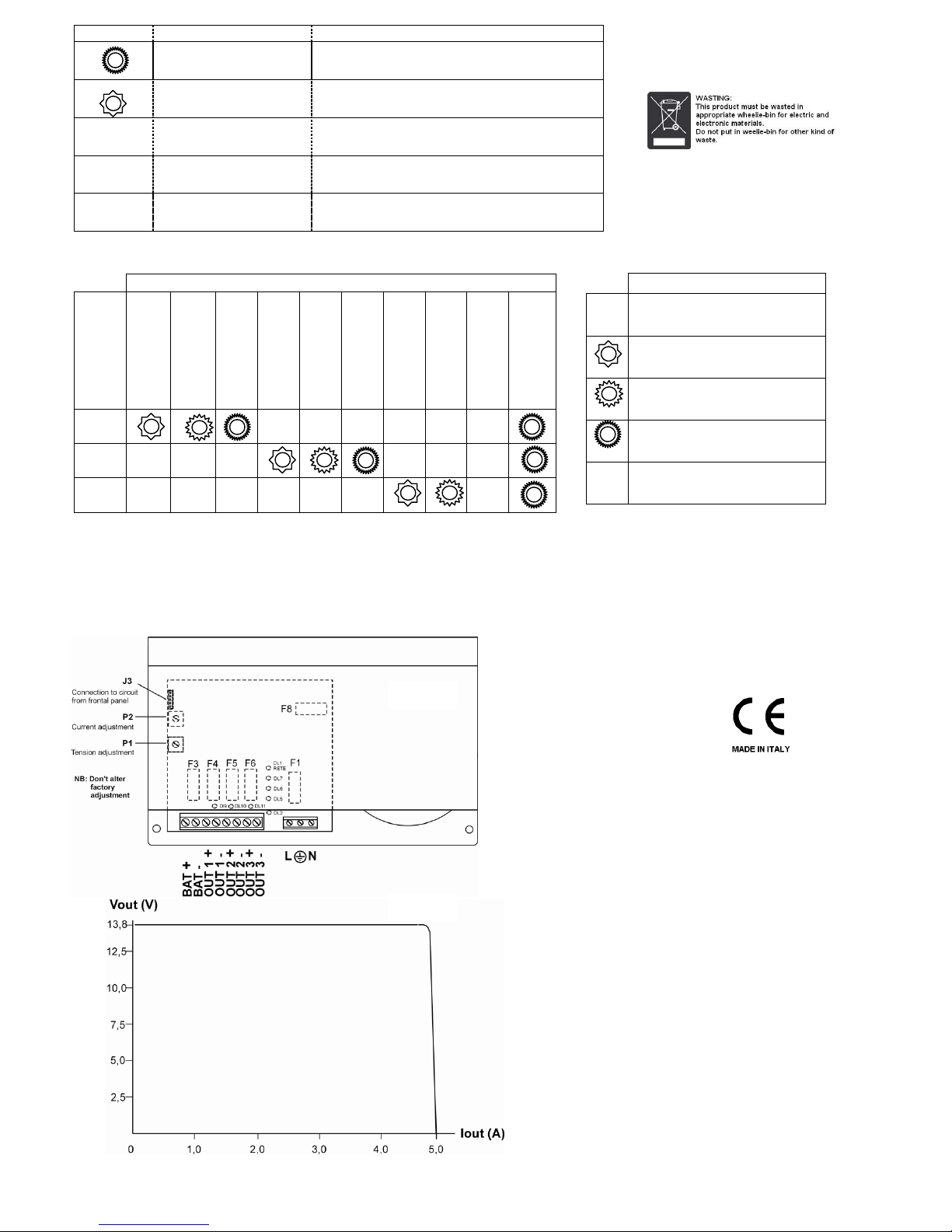
Leds in the control board (see Pict. 1) show:
Cut fuse for any of the outputs, with Led off (DL9, DL10, DL11)
Current consumption by the charge (2 green and 1 red, DL5, DL6, DL7)
Mains presence (DL1 RETE)
Failures (DL2)
Control of battery efficiency.
The power supply periodically controls the batteries efficiency:
-At first power supply activation, the microprocessor carries out the test of battery presence after 30 seconds. If battery is
connected, the test will be carried out periodically every 10 minutes whilst, if not connected, it will continue carrying out the
test every 20 seconds, showing the anomaly with DL2. This anomaly will be kept in memory until a battery is connected.
-During standard operating, the battery efficiency is checked watching batteries voltage. If batteries do not manage to
maintain an acceptable voltage during test, there will be activation of DL2.
-In case of missing mains, if the battery voltage is lower than 9,5Vdc, the battery and the charge are disconnected in order
to avoid malfunctioning of the system and to avoid deep discharge of the battery. The battery will be reconnected in case it
is replaced or in case of mains restore.
-During standard operating, a test of the battery internal resistance is carried out every 90 minutes; if the internal resistance
happens to be over 1 ohm, there will be on of DL2. It will then be necessary to replace the battery and check that terminals
and fuses have a good electrical contact. When the battery is replaced, having mains presence, the test of the internal
resistance is repeated within 5 minutes.
In order to avoid a possible failure damaging the charges or the battery, a protection circuit against over-voltages has been inserted,
made by a SCR and a fuse. There also is a fuse for alternated mains supplying. In case of failure in the power supply or of mains
absence, the battery will supply the electronic circuits.
Chart. 1
ELECTRICAL SPECIFICATIONS
Supplying voltage
230 Vac + 10% / - 15%
AC mains frequency
50 Hz sinusoidal
Current consumption from the mains
0,5 A max (at full charge)
Output voltage
13,8 Vdc (-15% / + 10%)
Minimum output voltage
9,5 Vdc at max charge, in mains absence and with discharged
battery
Voltage of switching-off threshold
9,5 Vdc
Max current consumption
5 A
Adjustment towards mains variations at full charge (+10% / -
15%)
Better than 1%
Adjustment towards charge variations (0 to 100%)
Better than 1%
Residual ondulation (ripple) at full charge
1Vpp (at 195,5 Vac) 30m Vpp (at 253 Vac)
Protection against inversion of battery polarity
Diodes
Alarm threshold of the battery internal resistance
1 ohm
Tension of intervention of the protection from overtensions
18Vdc
Dry-contact relay output for mains absence and failure
25 Vac or 60Vdc 1A max
Chart. 2
MECHANICAL SPECIFICATIONS
Size in mm.
Height 99; length 232; depth 183
Weight
3,1 Kilos
Chart. 3
ENVIRONMENTAL SPECIFICATIONS
Operating temperature
From –10°C to +40°C
Humidity
From 5% to 93% ±2%
Cooling
For convection
Installation site
In repaired position
Chart. 4
FUSES
F1
Fuse of the 230 Vac supplying input (T2 AL 250V)
F5
Fuse related to output OUT 2 (T3,15 AL 250V)
F3
Battery fuse (T6,3 AL 250V)
F6
Fuse related to output OUT3 (T3,15 AL 250V)
F4
Fuse related to output OUT 1 (T3,15 AL 250V)
F8
Fuse of protection over-voltage (T6,3 AL 250V)
Manual TL135 English rev1 Page 2 of 3
Security instructions
- For AC supplying, provide a 6 A protection bi-pole magneto-dynamic switch, easy to access.
- The wires must have a section of 1,5 mm and be equipped with adequate buttonholes where they are subject to
pressure contact.
- The installation of the power supply must be carried out by qualified personnel aware of the security standards EN60950
and concerning power supplies CEI-64-8.
INSTALLATION
Electrical connections
Connect the power supply to the mains 230 Vac by use of bi-pole 6 A magneto-thermic switch (minimum distance between contacts
3 mm) aimed to protect the line from possible short-circuits and to protect the operator from current losses towards ground.
IMPORTANT:
use different cable-passes and pipes for ac supplying input (mains 230 Vac) and dc outputs + alarms (SELV).
The minimum section recommended for ground connection is 1,5 mm.
For connections refer to figures Pict.1. In these pictures the following important steps are shown:
Chart. 5
Output terminal board (power supply)
BAT +
Positive pole of the battery
OUT 2 +
Positive output towards charge 2
BAT -
Negative pole of the battery
OUT 2 -
Negative output towards charge 2
OUT 1 +
Positive output towards charge 1
OUT 3 +
Positive output towards charge 3
OUT 1 -
Negative output towards charge 1
OUT 3 -
Negative output towards charge 3
Terminal board Alternated Supplying
L connection to line ( 230 Vac)
Protection ground connection
N connection to neutral
Controls and Adjustments
The parameters shown below (P1 and P2) are adjusted at factory and must in no way be altered by the operator.
Tampering of these parameters automatically means the lost of the warranty.
P1 Potentiometer for adjustment of the output voltage -- P2 Potentiometer for adjustment of the output current limit.
Start of the system
Even if not imperative, the following sequence of connection is suggested:
1. Connect mains and ground to the concerned terminal J1. The charge Led flashes and after about 30 seconds the missing
battery Led flashes
2. Connect the battery. After 20 seconds the Led switches off
3. Connect the charges: the Leds indicating the current supplied light up
Servicing
Periodical programmed servicing must be carried out by qualified personnel in order to prevent the possibility of a malfunctioning of
the power supply. It is recommended to carry out servicing every 6 months and to evaluate control panel of the system in order to
check possible alarms during tests.
- Check the connections of the 230 Vac supplying lines
- Check the connections of the alarm indication lines and related shields
- Check the battery connections, they have to be well tightened and there must be no oxidation
- Check the output voltage on the charge (see electrical specifications)
- Disconnect the battery and check if the voltage of the power supply is within the values shown.
- After re-connecting the battery, disconnect the primary supplying and check if the battery can maintain the voltage on the higher
12Vdc charge. On the contrary, replace battery immediately.
Led synoptic panel
The DL2 Led shows the failures:
In case of contemporary presence of more alarms, the Led indication follows the priority shown in the chart
Manual TL135 English rev1 Page 3 of 3
LEDS DL5 DL6 and DL7 show the current consumed by the outputs:
MANUFACTURER DECLARATIONS
We declare that:
- Project has been developed by our internal management system of quality control respecting all rules required
for a suitable planning.
- All components are selected for expected purpose and their characteristics are guaranteed if environmental
conditions outside coverings correspond to those specified for class 3K5 of the EN 60721-3-3:1995.
DL2
ALLARM
QUICK FLASHING
DISCONNECTED BATTERY
SLOW FLASHING
BATTERY RESISTANCE > 1 Ω

ON FIX
FUSE F3 (BATTERY) INTERRUPTED

ON FIX
FUSE F8 (MAINS) INTERRUPTED

OFF
NONE OF PREVIOUS FAILURES
CURRENT SUPPLIED
LED
I < 0, 5A
0,5A <I< 1A
1A <I< 1,5A
1,5A <I< 2A
2A <I< 2,5A
2,5A <I< 3A
3A < I < 3,5A
3,5A < I < 4A
4,5A < I < 5A
OVERCHARGED
I > 5A
DL7






DL6






DL5







LEGEND

LED OFF
SLOW FLASHING -1Hz
NORMAL FLASHING –2Hz
QUICK FLASHING –4Hz

LED ON FIX
NB:Non
modificare
i trimmer
Pict. 5
Fig. 4
Via del Lavoro, 10 - 30030 Salzano (VE)
Tel. (+39) 041 5740374 –Fax (+39) 041 5740388
Web site: www.venitem.com E-mail: [email protected]
FUSES
F1 –Fuse of the 230Vac supplying input
F8 –Fuse of protection over-voltage
F3 –Battery fuse
F4 –Fuse related to output Out 1
F5 –Fuse related to output Out 2
F6 –Fuse related to output Out 3
LED (when on)
DL5,DL6,DL7 –Current consumption by the charge
DL2 –Failures
DL1 –Mains presence
LED on output (when on)
DL9,DL10,DL11 –Fuse on corresponding output intact
Fig. 5
Pict. 1
Pict. 2

Other Venitem Power Supply manuals

Venitem TUL500EN User manual

Venitem

Venitem TUL500EN User manual

Venitem TUL132 User manual

Venitem

Venitem TUL132 User manual

Venitem TUL 272 User manual

Venitem

Venitem TUL 272 User manual

Venitem TUL375 User manual

Venitem

Venitem TUL375 User manual

Venitem TUL373 User manual

Venitem

Venitem TUL373 User manual

Venitem TUL 135 User manual

Venitem

Venitem TUL 135 User manual

Popular Power Supply manuals by other brands

TDK-Lambda HWS 1500/ME Series instruction manual

TDK-Lambda

TDK-Lambda HWS 1500/ME Series instruction manual

Emerson NetSure 5100 user manual

Emerson

Emerson NetSure 5100 user manual

Vertiv NetSure 2100 A31-S2 user manual

Vertiv

Vertiv NetSure 2100 A31-S2 user manual

Elsner KNX PS640-IP 2U installation instructions

Elsner

Elsner KNX PS640-IP 2U installation instructions

Cooler Master RS-600-ASAA user manual

Cooler Master

Cooler Master RS-600-ASAA user manual

TDK-Lambda CUS600M instruction manual

TDK-Lambda

TDK-Lambda CUS600M instruction manual

National Instruments NI PXI-1006 user guide

National Instruments

National Instruments NI PXI-1006 user guide

COUGAR XTC450 quick start guide

COUGAR

COUGAR XTC450 quick start guide

Ericsson GE MASTR II 19A149979P1 Maintenance manual

Ericsson GE

Ericsson GE MASTR II 19A149979P1 Maintenance manual

extronics iSCANPS operating manual

extronics

extronics iSCANPS operating manual

Siemens SITOP series operating instructions

Siemens

Siemens SITOP series operating instructions

Terra UP410 manual

Terra

Terra UP410 manual

hager TXA 112 manual

hager

hager TXA 112 manual

Notifier APS-6R instruction manual

Notifier

Notifier APS-6R instruction manual

dbx PS6 owner's manual

dbx

dbx PS6 owner's manual

SEW MDR60A operating instructions

SEW

SEW MDR60A operating instructions

Rockwell Automation Allen-Bradley 1606-XLE240EDRZ SER B installation instructions

Rockwell Automation

Rockwell Automation Allen-Bradley 1606-XLE240EDRZ SER B installation instructions

Ametek LAND 9100 Assembly guide

Ametek

Ametek LAND 9100 Assembly guide

manuals.online logo
manuals.online logoBrands
  • About & Mission
  • Contact us
  • Privacy Policy
  • Terms and Conditions

Copyright 2025 Manuals.Online. All Rights Reserved.