manuals.online logo
Brands
  1. Home
  2. •
  3. Brands
  4. •
  5. Venitem
  6. •
  7. Power Supply
  8. •
  9. Venitem TUL373 User manual

Venitem TUL373 User manual

MA-AL-T73E-01-03 Manual TUL373EN eng rev3 Rev.3 Page 1 of 4
POWER SUPPLY TUL373 EN
CERTIFIED UNI EN54-4:2007. Included updating A1:2002 and A2:2006
Installation Manual
GENERAL FEATURES
The power supply TUL 373 EN has been designed to be used as power unit with energy stock in the fire security systems in conformity
to regulation (EU) No 305/2011.
Its electrical and mechanical features make it be conform to the norm EN 54-4:1997 + A1:2002+A2:2006 (Systems for detection and
fire indication: Part 4: supplying devices).
FUNCTIONAL FEATURES
The power supply unit is made by a linear power supply, series adjustment, with serial voltage regulator, limited in constant precision
current (rectangular limitation), two 12V 17 Ah batteries (not given within) analogical control circuit and micro-controlled supervision
circuit.
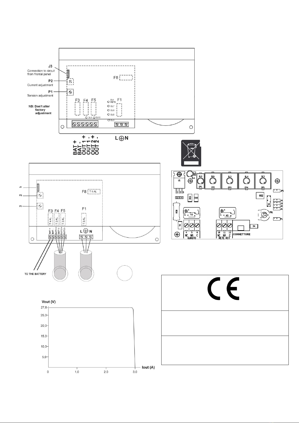
Supplying is divided on 3 terminal-outputs protected by fuses:
BAT: where the back-up battery will be connected
OUT 1 and OUT2: for generic charges
The charge of the battery occurs at constant tension (27,6 V @ 25°C) with temperature compensation and current limitation.
The maximum current supplied by the power supply is 3 A with 2 A for charge and 1 A for the battery.
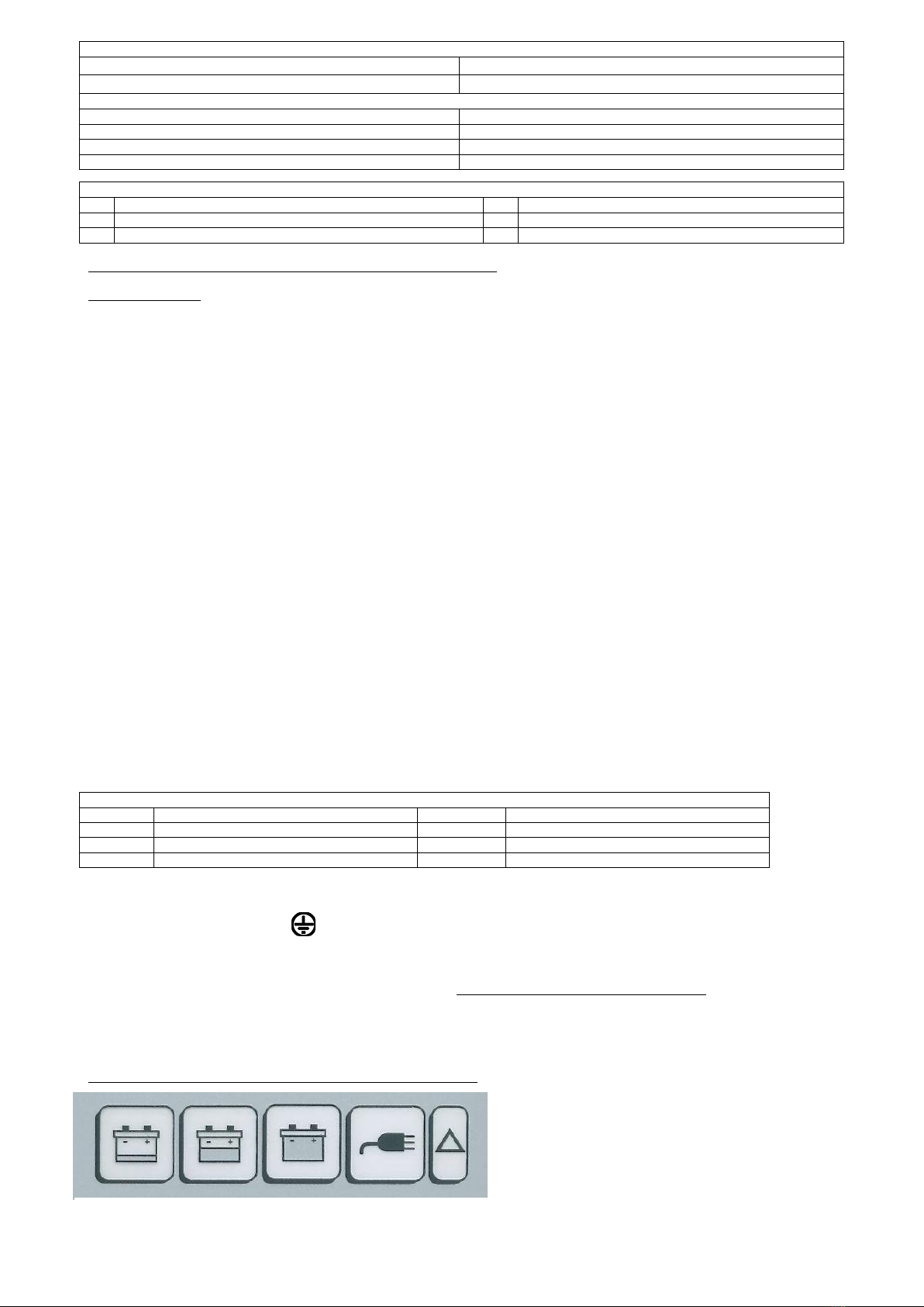
The LED on the control board are close to concerned fuses (see pict.1) and show:
-Fuse cut for any of the outputs, with Led off (DL9, DL10)
-Current consumed by charge (2 green and one red DL5, DL6, DL7)
-Mains presence (DL1 RETE)
Check of battery efficiency
The power supply periodically carries out the efficiency of the batteries:
At first activation of the power supply , the microprocessor will carry out the test of battery presence after about 30 seconds. If
connected, the test will be carried out every 10 minutes whilst in case it is not connected, it will continue carry out the test every 20
seconds showing indication FAILURE.
During normal functioning, the efficiency of the battery is checked by controlling the batteries tension. If batteries do not manage to
maintain an acceptable tension during test, there will be the indication FAILURE.
A test of the internal resistance of the battery is carried out during normal functioning, every 1,5 hours (in conformity to attachment
EN54-4/A2); if the internal resistance is over 1 ohm, there will be a FAILURE indication. It will then be necessary to replace the
batteries and check that terminals and fuses have a good electrical contact. When the battery is replaced, with presence of mains
tension, the test of internal resistance is repeated every 5 minutes.
A microcontroller system controls various possible anomalies and gives a FAILURE indication in the following conditions:
1. Output Fuses interruptions
2. Overloaded Battery (> 30 V)
3. Low Battery Tension (< 21 V)
4. Power absence and no battery charge
5. Disconnected Battery
6. Internal battery resistance >1 Ώ
The indication of failure together with the indication of mains absence are in a connector placed on the control and supervision board.
In order to avoid that a possible failure in the series regulator damages the charges or the battery, a protection circuit has been inserted
against over-tensions, made of a SCR and a fuse. A fuse for mains alternated supplying is also present.
In case of failure in the power supply or of mains missing, supplying of the logic and control circuits occurs by means of battery.
.
Electrical Specifications
Supplying tension
230 Vac +10% / -15%
Ac mains frequency
50 Hz sinusoidal
Current consumption by mains
1,1 A max. ( full load )
Output tension
27,6 Vdc ( -15% / +10%)
Minimum output tension
20 Vdc at max charge, with mains absence and battery
discharged
Switching-off threshold tension
20 Vdc
Output current
3 A max. (see pict.4)
Max current for battery recharge
1 A
Max current for charges
2 A
Regulations towards mains variations at full charge (+10% / -15%)
Better than 1%
Regulations towards charge variations (0 to 100%)
Better than 1%
Ripple at full charge
1 Vpp ( at 195,5 Vac ) 30mVpp ( at 253 Vac )
Compensation of output tension according to temperature
4 mV/ K
Protection against battery polarity inversion
Diode
Recommended batteries: 2 x 12 V in series, 17 Ah housing with
inflammability class UL-94-V2 or better
Type:YUASA NP 17-12 or equivalent.
Alarm threshold of battery internal resistance
1Ω
Missing mains and failure output relay –dry contacts
25 Vac or 60 Vdc 1A MAX
MA-AL-T73E-01-03 Manual TUL373EN eng rev3 Rev.3 Page 2 of 4
Low battery: control tension lower than 22 Vdc
Battery ok: tension included between 22 Vdc and 28,5 Vdc
Overcharged battery: tension over 28,5 Vdc
Mains: presence of line tension 230 Vac
Failure : Led of general failure, it activates in case of:
Absence of 230 Vac mains
Faulty fuse
Loss of battery charge
Low battery
Overcharged battery
Disconnected battery
Battery resistance > 1 ohm
The power supply has been certified using YUASA NP 17-12 batteries
Security Instructions
For mains input and DC outputs + alarms, use separate holes on the bottom of the box to pass the cables. Furthermore, the
material of the joint pipe/box must have a flammability class V-1 or better
The relay contact “GUASTO” and “RETE RIT ” must be connected only to circuits operating with SELV tension.
For AC supplying, provide a 6 A protection bi-pole magneto-dynamic switch, easy to access
The wires must have a section of 1,5 mm and be equipped with adequate buttonholes where they are subject to pressure
contact.
The installation of the power supply must be carried out by qualified personnel aware of the security norms EN60950 and
concerning power supplies CEI-64-8.
IMPORTANT: In case of mains failure and general anomaly condition, a technical intervention should be carried out
within 48 hours to avoid the complete discharge of the battery.
INSTALLATION
MECHANICAL MOUNTING
This device has to be mounted on vertical stable walls, suitable to support the power supply, by means of 4 6 mm screws, for spacers
and screws on the 4 holes on the bottom of the box. The battery must be fixed using the strap given within.
ELECTRICAL CONNECTION
Connect the power supply unit to the mains 230 Vac by use of a differential magneto-thermic bipolar 6 A. switch (minimum distance
between contacts 3 mm) aimed to protect the line against possible short circuit and operator against current leakage.
IMPORTANT: use different cables-passes and pipes for ac supplying input (mains 230 Vac) and dc outputs + alarms (SELV) –see
pict. 2
The minimum section recommended for ground connection is 1,5 mm.
For connections refer to pictures 1 and pict. 2.In these pictures the following important steps are shown:
Output Terminals (Power supply unit)
Output terminal board (power supply)
BAT +
Positive pole of the battery
OUT 2 +
Positive output towards charge 2
BAT -
Negative pole of the battery
OUT 2 -
Negative output towards charge 2
OUT1 +
Positive output towards charge 1
OUT1 -
Negative output towards charge 1
Terminal board Alternated Supplying
L connection to line (230 Vac) Protection ground connection N connection to neutral
Checks and Adjustments
Controls are shown Below (P1 and P2) are adjusted at factory and must in no way be altered by the operator.
Tampering of these controls automatically means the lost of the warranty.
P1 - Potentiometer for adjustment of the output tension P2 - Potentiometer for adjustment of the output current limit.
FRONT PANEL SIGNALS
Indications on the front panel (located on the door of the power supply)
Mechanical Specifications
Size in mm.
width 310 ; height 373 ; depth 170
Weight
9,5 Kg
Environmental Specifications
Operating temperature
from -5 °C to +40 °C
Humidity
from 5% to 93% ± 2 %
cooling
air cooling
Installation site
sheltered from atmospheric agents
FUSES
F1
Fuse of the 230 Vac supplying input (T2 AL 250V)
F5
Fuse related to output OUT 2 (T2 AL 250 V)
F3
Battery fuse (T4 AL 250 V)
F8
Fuse of protection over-tension (T5 AL 250 V)
F4
Fuse related to output OUT 1 (T2 AL 250 V)
Low battery Battery OK Overcharged Mains Failure
battery
MA-AL-T73E-01-03 Manual TUL373EN eng rev3 Rev.3 Page 3 of 4
Connection of control board (placed behind the front panel)
Refer to picture 3
Relay “mains missing” – Terminals 10 –11 –12 (operating with SELV tensions)
Relay output with intervention for missing mains and programmable activation delay
Jumper on JP1 to have a delay of 15 seconds jumper on J3 to have a delay of 120 minutes
Jumper on J1 to have a delay of 15 minutes jumper on J4 to have a delay of 240 minutes
Jumper on J2 to have a delay of 60 minutes
In order for the power supply to be in conformity to the certification , the jumper must be set on JP1 or J1, as the norm talks
about a max delay of 30 MINUTES of missing mains. On the contrary, the conformity decades.
Note: if no jumper is inserted, the “mains missing” relay will never activate.
Relay of “failure indication” – Terminals 4 –5 –6 (operating with SELV tensions)
Relay output for failure indication, it is active for:
Low battery (tension lower than 22 Vdc)
Overcharged battery (tension over 28,5 Vdc)
Resistance battery > 1 ohm
Start of the system: even if not imperative, the following sequence of connection is suggested:
1. Connect mains and ground to the concerned terminal J1. The charge Led flashes and after about 30 seconds the missing
battery Led flashes
2. Connect the battery. After 20 seconds the Led switches off
3. Connect the charges: the Leds indicating the current supplied light up
SERVICING
Periodical programmed servicing must be carried out by qualified personnel in order to prevent the possibility of a malfunctioning of the
power supply. It is recommended to carry out servicing every 6 months and to evaluate control panel of the system in order to check
possible alarms during tests.
Check the connections of the 230 Vac supplying lines
Check the connections of the alarm indication lines and related shields
Check the battery connections, they have to be well tightened and there must be no oxidation
Check the output tension on the charge (see electrical specifications)
Although the power supply is equipped with a self-diagnosis system carrying out a periodical control of the battery and indicating
possible failures, it is suggested to manually check the battery every six months.
Disconnect the battery and check if the tension of the power supply is within the values shown.
After re-connecting the battery, disconnect the primary supplying and check if the battery can maintain the tension on the higher 23 Vdc
charge. On the contrary, replace battery immediately.
Check presence of related alarms during tests.
LED SYNOPTIC PANEL
The DL2 Led shows the failures:
In case of contemporary presence of more alarms, the Led indication follows the priority shown in the chart
DL2
ALARM
Quick flashing
Disconnected battery
Slow flashing
Battery resistance > 1 ohm
On fix
Fuse F3 (battery) interrupted
On fix
Fuse F8 (mains) interrupted
Off
None of previous failures
Leds DL5, DL6 and DL7 show the current consumed by the outputs:
Condition
LED Status
DL5
DL6
DL7
I < 0,25 A
OFF
OFF
SLOW FLASH
0,25A < I <0,6 A
OFF
OFF
FLASH
0,6A < I <0,9A
OFF
OFF
QUICK FLASH
0,9A < I < 1,3A
OFF
SLOW FLASH
FIX ON
1,3A < I < 1,7A
OFF
FLASH
FIX ON
1,7A < I < 2,1A
OFF
QUICK FLASH
FIX ON
2,1A < I < 2,4A
SLOW FLASH
FIX ON
FIX ON
2,4A < I < 2,8A
FLASH
FIX ON
FIX ON
2,8A < I < 3A
FIX ON
FIX ON
FIX ON
OVERCHARGE I > 3A
QUICK FLASH
QUICK FLASH
QUICK FLASH
Note: SLOW FLASH = 1 Hz –FLASH 2 Hz –QUICK FLASH = 4 Hz
MA-AL-T73E-01-03 Manual TUL373EN eng rev3 Rev.3 Page 4 of 4
MANUFACTURER DECLARATIONS
Statement of the Manufacturer:
The design has been developed according to the internal quality system respecting a series of rules aimed to reach an adequate
design of all the elements of the product.
All components of the product have been selected for the forecasted purposes and their characteristics are assured when the weather
conditions correspond to the conditions required by class 3K5 of EN 60721-3-3:1995
Tel. (+39) 041 5740374 –Fax (+39) 041 5740388 Web www.venitem.com E-mail [email protected]
0051
Venitem s.r.l. Via del Lavoro, 10 - 30030 Salzano (VE)
16
DoP 0051 - CPR - 0266
EN54-4
Power supply equipment
for fire detection and fire alarms systems
TUL373EN
Wasting
This product must be wasted in appropriate
wheelie-bin for electric and electronic materials.
Do not put in wheelie-bin for other kind of
waste.
FUSES
F1 –Fuse of the 230 Vac supplying input
F8 –Fuse of protection over-tension
F3 –Battery fuse
F4 –Fuse Out 1
F5 –Fuse Out 2
LED (when ON)
DL5,DL6,DL7 - Current consumed by charge
DL2 –Power supply anomaly
LED output (when ON)
DL9,DL10 –Intact fuse on corresponding output
Pict. 1
Pict. 2
Pict. 3
Pict. 4

Other Venitem Power Supply manuals

Venitem TUL500EN User manual

Venitem

Venitem TUL500EN User manual

Venitem TUL132 User manual

Venitem

Venitem TUL132 User manual

Venitem TUL 272 User manual

Venitem

Venitem TUL 272 User manual

Venitem TUL375 User manual

Venitem

Venitem TUL375 User manual

Venitem TL 135 Guide

Venitem

Venitem TL 135 Guide

Venitem TUL 135 User manual

Venitem

Venitem TUL 135 User manual

Popular Power Supply manuals by other brands

LITELINE LED-HWB-24V-100W quick start guide

LITELINE

LITELINE LED-HWB-24V-100W quick start guide

Elenco Electronics XP-4 operating manual

Elenco Electronics

Elenco Electronics XP-4 operating manual

Stromtank S 5000 owner's manual

Stromtank

Stromtank S 5000 owner's manual

TDK-Lambda HWS 1500/ME Series instruction manual

TDK-Lambda

TDK-Lambda HWS 1500/ME Series instruction manual

LRP electronic 43200 user manual

LRP electronic

LRP electronic 43200 user manual

GE Infinity M Series installation guide

GE

GE Infinity M Series installation guide

Puls PIANO Series installation instructions

Puls

Puls PIANO Series installation instructions

ADEMCO PS 24 installation instructions

ADEMCO

ADEMCO PS 24 installation instructions

phytron SLS-C manual

phytron

phytron SLS-C manual

Olympus TH4 instructions

Olympus

Olympus TH4 instructions

Datalogic PWR-240B installation manual

Datalogic

Datalogic PWR-240B installation manual

Redarc DPS1225 manual

Redarc

Redarc DPS1225 manual

H3C PSR1600-54A-B user manual

H3C

H3C PSR1600-54A-B user manual

GW Instek PFR-100 Series Programming guide

GW Instek

GW Instek PFR-100 Series Programming guide

Spellman uX SERIES instruction manual

Spellman

Spellman uX SERIES instruction manual

Analog Technologies AHVAC40WBT manual

Analog Technologies

Analog Technologies AHVAC40WBT manual

JVA Z Series manual

JVA

JVA Z Series manual

Lambda ESKI instruction manual

Lambda

Lambda ESKI instruction manual

manuals.online logo
manuals.online logoBrands
  • About & Mission
  • Contact us
  • Privacy Policy
  • Terms and Conditions

Copyright 2025 Manuals.Online. All Rights Reserved.