Ventis MX4 User manual

1
Multi-gas Monitor
Product Manual
Set-up
Operation
Service
Part Number: 17152357-1
Version 11

Ventis™ MX4 Product Manual
© 2014Industrial Scientific Corporation 2
Table of Contents
COPYRIGHT NOTICE ...................................................................................................................................................3
WARNINGS AND CAUTIONARY STATEMENTS ........................................................................................................3
General ...................................................................................................................................................................3
Personnel ...............................................................................................................................................................3
Hazardous Conditions, Poisons, and Contaminants ..............................................................................................3
General Usage .......................................................................................................................................................4
Agency-issued Conditions of Use and Warnings ....................................................................................................4
Recommended Practices .......................................................................................................................................5
VENTIS MX4™ RESOURCES.......................................................................................................................................6
VENTIS MX4 CAPABILITIES........................................................................................................................................6
UNPACKING THE MONITOR .......................................................................................................................................7
Contents..................................................................................................................................................................7
Reporting a Problem ..............................................................................................................................................7
MONITOR OVERVIEW .................................................................................................................................................8
Hardware Features and Functions..........................................................................................................................8
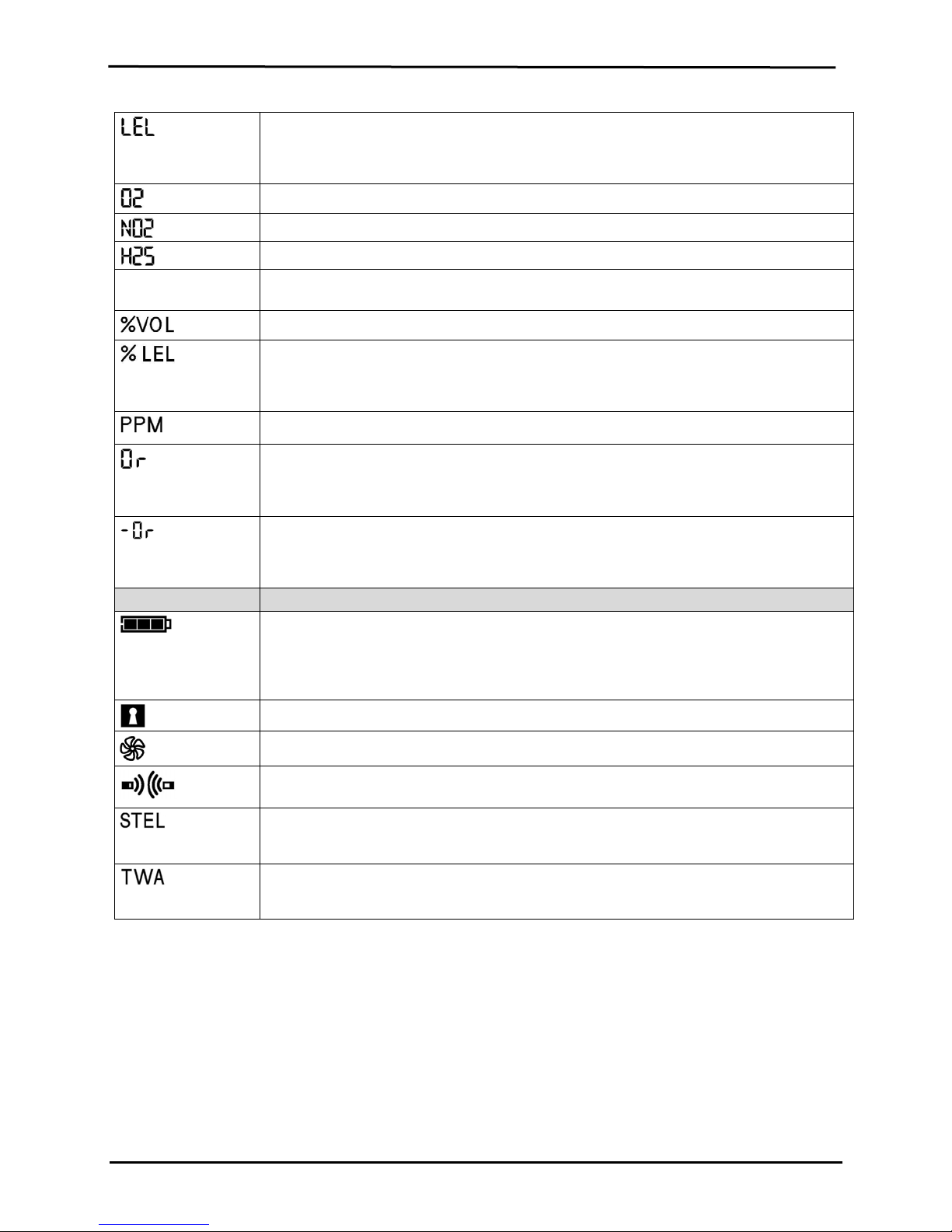
Display Screen........................................................................................................................................................9
Alarms...................................................................................................................................................................11
MONITOR SET-UP ......................................................................................................................................................13
Battery Properties and Monitor Compatibility .......................................................................................................13
Charging the Lithium-ion Battery Packs ...............................................................................................................14
Instruction ......................................................................................................................................................14
Power-on and –off.................................................................................................................................................15
Configuration.........................................................................................................................................................16
Introduction ....................................................................................................................................................16
Instructions ....................................................................................................................................................16
Configuration Process....................................................................................................................................17
MONITOR USE AND SERVICE ..................................................................................................................................24
Zero, Calibration, and Bump Testing ....................................................................................................................24
Procedures ....................................................................................................................................................24
Recommendations.........................................................................................................................................25
General Information ..............................................................................................................................................25
Instructions ...................................................................................................................................................26
Recommended Practices for In-field Air Sampling ...............................................................................................32
Cleaning ...............................................................................................................................................................32
Service..................................................................................................................................................................33
Battery Packs.................................................................................................................................................33
Monitor Conversion .......................................................................................................................................36
Sensor, Sensor Water Barrier, LCD, and Vibrating Motor Replacement........................................................38
Pump Module.................................................................................................................................................40
Ventis MX4 Three-Dimensional View Diagrams ............................................................................................41
PRODUCTS, SPECIFICATIONS, AND CERTIFICATIONS ........................................................................................44
Ventis MX4 Accessories and Parts .......................................................................................................................44
Monitor Specifications...........................................................................................................................................46
Operating Conditions ............................................................................................................................................46
Storage Conditions ...............................................................................................................................................47
Sensor Specifications ...........................................................................................................................................47
Toxic Gas Sensor Cross-Sensitivity Table ............................................................................................................47
LEL and LEL Correlation Factors for Combustible Gases ....................................................................................48
Certifications .........................................................................................................................................................49
WARRANTY ................................................................................................................................................................50
Limitation of Liability..............................................................................................................................................50
INDUSTRIAL SCIENTIFIC CORPORATION GLOBAL LOCATIONS.....................................................BACK COVER

Ventis™ MX4 Product Manual
3 © 2014 Industrial Scientific Corporation
►Copyright Notice
Ventis MX4™ and Ventis™ are trademarks of Industrial Scientific Corporation.
All trademarks and registered trademarks are the property of their respective owners.
These help materials or any part thereof may not, without the written consent of Industrial Scientific Corporation, be
copied, reprinted, or reproduced in any material form including but not limited to photocopying, transcribing,
transmitting, or storing it in any medium or translating it into any language, in any form or by any means, be it digitally,
electronic, mechanical, xerographic, optical, magnetic, or otherwise.
The information contained in this document is proprietary and confidential and all copyright, trademarks, trade names,
patents, and other intellectual property rights in the documentation are the exclusive property of Industrial Scientific
Corporation unless otherwise specified. The information (including but not limited to data, drawings, specification,
documentation, software listings, source or object code) shall not at any time be disclosed directly or indirectly to any
third party without prior written consent.
The information contained herein is believed to be accurate and reliable. Industrial Scientific Corporation accepts no
responsibility for its use by any means or in any way whatsoever. Industrial Scientific Corporation shall not be liable
for any expenses, costs by damage that may result from the use of the information contained within this document.
Although every effort is made to ensure accuracy, the specifications of this product and the content herein are subject
to change without notice.
►Warnings and Cautionary Statements
General
IMPORTANT
Failure to perform certain procedures or note certain conditions may impair the performance of this
product. For maximum safety and optimal performance, please read and understand the Ventis MX4
Product Manual available online at the Ventis MX4 Resource Center at
www.indsci.com/ VentisMX4resources.
Personnel
CAUTION: For safety reasons, this equipment must be operated and serviced by qualified personnel only.
Read and understand the product manual completely before operating or servicing.
Hazardous Conditions, Poisons, and Contaminants
WARNING: Servicing the unit, replacing or charging battery packs, or using the communications port must only
be done in an area known to be nonhazardous. Not for use in oxygen-enriched atmospheres.
WARNING: Power-off the monitor before servicing the unit or replacing the battery.
WARNING: Substitution of components may impair intrinsic safety and may cause an unsafe condition.
CAUTION: High off-scale readings may indicate explosive gas concentration(s).
CAUTION: Any rapid up-scale reading followed by a declining or erratic reading may indicate gas
concentration(s) beyond the upper scale limit which may be hazardous.
Silicone compound vapors or other known contaminants may affect the combustible gas sensor and cause
readings of combustible gas to be lower than actual gas concentrations. If the monitor has been used in an
area where silicone vapors were present, always calibrate the monitor before next use to ensure accurate
measurements.

Ventis™ MX4 Product Manual
© 2014Industrial Scientific Corporation 4
General Usage
Oxygen-deficient atmospheres may cause combustible gas readings to be lower than actual concentrations.
Oxygen-enriched atmospheres may cause combustible gas readings to be higher than actual concentrations.
Sudden changes in atmospheric pressure may cause temporary fluctuations in the oxygen reading.
Verify the calibration of the combustible gas sensor after any incident where the combustible gas content has
caused the monitor to display an over-range condition.
Sensor openings, water barriers, and the pump inlet must be kept clean. Obstruction of the sensor openings or
pump inlet and/or contamination of the water barriers may cause readings to be lower than actual gas
concentrations.
To avoid the potential of liquid being pulled into the sample tubing and pump assembly, it is recommended that
Industrial Scientific filter (P/N 17027152) be used on the sample tubing when drawing samples using the
aspirated monitor.
WARNING: INSERT THE ALKALINE BATTERIES WITH THE CORRECT POSITIVE “+” AND NEGATIVE “-“
ORIENTATION. WARNING: The Ventis MX4 is only approved for use with AAA battery types Energizer EN92
and Duracell MN2400. Do NOT mix battery types.
WARNING: The use of leather cases can produce inaccurate readings with diffusion (non-aspirated) gas
detection instruments for specific monitoring applications. Leather cases should be used ONLY as carrying
cases, and NOT for continuous monitoring, with diffusion instruments configured to measure gases other than
O2, CO, CO2, H2S, and combustible gases (LEL/CH4).
Agency-issued Conditions of Use and Warnings
Ensure all part-use restrictions (e.g., battery) meet any agency-mandated conditions of use.
Ensure all instrument-configurable settings (e.g., always-on setting) meet any agency-mandated conditions of
use. When using instrument-compatible Industrial Scientific docking stations, maintain mandated settings
through the software (e.g., iNet Control or Accessory Software) or by manually configuring the instrument
settings after docking.
The Ventis MX4 is CSA certified according to the Canadian Electrical Code for use in Class I, Division 1 and
Class I, Zone 1 Hazardous Locations within an ambient temperature range of Tamb: -20°C to +50°C. CSA has
assessed only the %LEL combustible gas detection portion of this instrument for performance according to
CSA Standard C22.2 No. 152. This is applicable only when the monitor is used in the diffusion mode and has
been calibrated to 50% LEL CH4, and when the monitor is used in the aspirated mode with an extended range
lithium-ion battery and has been calibrated to 50% LEL CH4.
CAUTION: CSA C22.2 No. 152 requires before each day’s usage, sensitivity must be tested on a known
concentration of pentane or methane equivalent to 25% or 50% of full scale concentration. Accuracy must be
within -0% to +20% of actual concentration. Accuracy may be corrected by referring to the zero/calibration
section of the Product Manual.
The equipment complies with the standards IEC 60079-29-1 and EN 60079-29-1 for methane, propane, and
hexane with the following exception: as for the methane (mine) detector, the battery run time was verified to be
seven (7) hours rather than the eight (8) hours recommended by the standards, respectively.
MED-certified instruments may be used only when configured and maintained to disallow power-off when the
unit is in alarm.
The Mine Safety and Health Administration (MSHA) has approved the Ventis MX4 as a Permissible Multi-Gas
Monitor with the following warnings:
MSHA approved for use with either the P/N 17134453-X2, 3.7 volt, lithium-ion battery or P/N 17148313-2,
3.7 volt, lithium-ion extended battery pack assembly only. The battery pack is not user-replaceable. The
monitor battery and the lithium battery on the main PCB are technician replaceable only. Charge battery
pack with an ISC battery charger designed for use with this monitor in fresh air locations only.

Ventis™ MX4 Product Manual
5 © 2014 Industrial Scientific Corporation
The monitor is to be calibrated according to the procedures in the instruction manual only.
The aspirated version of the Ventis MX4 is only approved for use with the extended battery pack.
The monitor must display methane in the percent-by-volume mode (0-5%) for compliance determinations
required by 30 CFR Part 75, subpart D.
SANS 1515-certified units may be used only as follows:
Diffusion applications
Configured and maintained to disallow power-off when the unit is in alarm
The Methane alarms are set as follows: low alarm = 1%vol and high alarm =1.4%vol
With approved Lithium-ion battery packs (see Ventis MX4 Accessories and Parts in this manual).
Recommended Practices
Industrial Scientific Corporation recommends the monitor be fully charged (when equipped with a rechargeable
battery pack), configured, and calibrated before first time use. If the lithium-ion battery is deeply discharged, it
can take up to an hour for the instrument display to indicate that the battery is charging. Monitors used
infrequently should be fully charged every four months.
No part of the unit should be covered by any garment, part of a garment, or other item that would restrict the
flow of air to the sensors or impair the operator's access to the audible, visual, or vibration alarms.
Industrial Scientific Corporation recommends a full monitor calibration be performed monthly (at a minimum),
using a certified concentration(s) of Industrial Scientific calibration gas(es) to help ensure monitor accuracy.
Industrial Scientific Corporation recommends the monitor be zeroed and bump tested before each use with a
certified concentration(s) of Industrial Scientific calibration gas(es).
Battery contacts are exposed on battery packs when they are removed from the monitor. Do not touch the
battery contacts and do not stack battery packs on top of one another.
When reassembling the instrument or installing a battery pack, maintain ingress protection by tightening each
fastener to its stated torque value (see the “Ventis MX4 Monitor three-Dimensional Diagram” and its key in this
manual).
Contact your service representative immediately if you suspect that the Ventis MX4 is working abnormally.
Industrial Scientific recommends the “2 & 2 Sampling Rule” when sampling with a motorized pump and tubing,
one should allow for 2 minutes plus 2 seconds per foot of tubing used, prior to noting the monitor readings.
This allows time for the gas to reach the instrument and for the sensors to adequately react to any gases
present. Industrial Scientific recommends that clear urethane tubing, part number 17065970, be used with the
pumped versions of the Ventis MX4 when sampling for the following gases: Nitrogen Dioxide (NO2) and Sulfur
Dioxide (SO2).

Ventis™ MX4 Product Manual
© 2014Industrial Scientific Corporation 6
►Ventis MX4 Resources
The Ventis MX4 Product Manual is the primary resource, within a full suite of learning tools, developed for the monitor
user. Its step-by-step “walk through” format covers everything from unpacking to set-up, operation, and service. All
Ventis MX4 users should read and understand the Product Manual prior to unpacking or using the monitor.
A companion to the manual, the Ventis MX4 Reference Guide ships with the monitor. It serves to announce all
warnings and cautionary statements relevant to general monitor use. The guide also features process charts that
provide an overview of four fundamental tasks: operation/start-up, configuration, calibration, and functional “bump”
testing. These charts are tools for the user who is both familiar with the manual and proficient in the performance of
the given task.
Ventis MX4 product-specific resources are part of the organization’s broader training line-up, featuring online training
modules and face-to-face classroom programs for technicians, operators, first responders, trainers, and distributors.
Courses combine theory with hands-on learning, and can be tailored to the customer’s unique requirements and gas
monitoring applications.
The organization’s customer and technical support call centers provide product and order information, how-to product
assistance, and guidance for in-depth technical applications. Its service centers offer comprehensive factory repair
and maintenance services.
Industrial Scientific Corporation provides a full suite of resources to aid customers in the competent and safe use of
its products and services. With 19 manufacturing, support, and service centers and hundreds of distributors
worldwide, Industrial Scientific serves the globe’s gas detection needs.
►Ventis MX4 Capabilities
The Ventis MX4 is a portable multi-gas monitor. Offered as a diffusion monitor, it detects and measures gas(es)
present in open space. To enable monitor use within confined space locations, the Ventis MX4 is also offered as an
aspirated monitor. A pump module and battery accessories enable the conversion of either monitor for dedicated use
in either confined or open spaces.
Based on the customer’s monitor order, up to four sensors are factory installed enabling the monitor to continuously
and simultaneously detect and measure the presence of up to four specific gases.
Sensor
Category
Number available per
monitor
Gases Monitored
Oxygen 1 O2(Oxygen) only
Combustible 1 Monitor can be configured for sensor to measure ONE of the following:
LEL (Pentane)
LEL (Methane)
CH4(0%-5%)
Toxic 2 Each sensor detects and measures only ONE of the following:
CO (Carbon Monoxide)
CO/H2 Low (Carbon Monoxide with low H2interference)
H
2S (Hydrogen Sulfide)
NO2(Nitrogen Dioxide)
SO2(Sulfur Dioxide)
Equipped with a multi-mode (audible, visual, and vibration) and multi-level alarm system, the Ventis MX4 monitor is
capable of notifying its user of potentially hazardous gas concentrations.
The monitor performs continuous datalogging at 10 second intervals. It can store approximately 90 days of data for a
four-sensor configuration. Its date- and time-stamped event log records and stores data for the following: 60 alarm
events, 30 error events, and 250 manually performed calibrations or bump tests. The memory, when full, overwrites
the oldest data as the newest readings and events are logged.

Ventis™ MX4 Product Manual
7 © 2014 Industrial Scientific Corporation
The Ventis MX4 monitor functions as an independent device to monitor the environment for hazardous gas
concentrations. It is also part of the Ventis System including products that charge, calibrate, bump test, datalink,
protect, and otherwise enable or enhance use of the monitor and its data. (Datalink refers to capabilities that enable
access to the download and use of monitor datalogs, reports, and other information.) For a complete list of the Ventis
MX4 system of products, please refer to the manual section, Products and Parts.
►Unpacking the Monitor
CONTENTS
The monitor box contains the following items including, when ordered, those marked optional. Each item ordered
should be accounted for in the unpacking process.
Quantity Item Notes
1 as ordered Ventis MX4 Portable Multi-gas
Monitor
The monitor type is indicated on the box label.
Options:
Ventis MX4 Diffusion
Ventis MX4 Aspirated
Ventis MX4 Aspirated with Conversion Kit
1 Ventis MX4 Reference Guide A companion to the Ventis MX4 Product Manual.
1 installed as ordered
Battery Pack
One of three battery types is factory installed as
indicated on the box label. Options:
Rechargeable Lithium-ion
Rechargeable Extended Range Lithium-ion
Alkaline
1 as ordered Charger Universal power cord. AC charger products include
interchangeable plugs (US, UK, EU, and AUS).
0 or 1 Calibration Cup Diffusion – 1 included
Aspirated – 0 included
1 Calibration and Bump Test
Tubing
Diffusion – two feet of clear tubing
0 or 1 In-field Sampling Tubing Diffusion – 0 included
Aspirated – Ten feet of black tubing
1 Final Inspection & Test Report Contains the following factory set* information:
Monitor Set-up Date
Monitor Part Number (P/N)
Monitor Serial Number (S/N)
For Each Sensor*:
P/N
S/N
Type
Location
Alarm level values
Span gas values
Span reserve values
*Some factory set sensor values subject to user changes.
1 Warranty Card --
REPORTING A PROBLEM
After unpacking, if any item is missing or appears to have been damaged, contact a local distributor of Industrial
Scientific products or Industrial Scientific Corporation (for contact information, please see the manual’s last page).

Ventis™ MX4 Product Manual
© 2014Industrial Scientific Corporation 8
►Monitor Overview
HARDWARE FEATURES AND FUNCTIONS
The monitor’s case top (front of monitor) has two main sections. As shown below, the upper section contains the
sensor ports. The lower section houses the user interface features, a LCD display screen and two buttons. Each
feature’s general functions are noted below. As shown, the diffusion and aspirated monitors differ with respect to the
location of the air intake mechanism and visual alarm indicators.
The instrument may be used in any orientation when clipped to the user or when used with a compatible carrying
case. Normal instrument orientation for measuring gas concentration is hand held with sensors and display facing the
operator.
Numbe
r
Feature Functions
1 Visual alarm indicator Signals an alarm or warning; frequency varies by alarm level. Also used as a
confidence indicator.
2 Pump inlet (aspirated)
Sensor ports (diffusion)
Air intake; calibration and bump test gas intake.
3 LCD display User interface; backlight flashes when monitor is in system, high, or low alarm
states.
4 Audible alarm ports On when monitor is in system, high, or low alarm states; frequency and tone vary
by alarm level. Also used for warnings and as confidence indicator.
5 On/Off/Mode button
Used to power-on and power-off. Also used to bypass a process/step or advance
to a next screen in both gas monitoring and configuration modes. Sets values in
configuration mode.
6 Enter button Used to begin a process/step in a process. Edits values in configuration mode.
7 IrDA interface Indicates infrared light data exchange in-progress.
8 Charging contacts Battery charging.

Ventis™ MX4 Product Manual
9 © 2014 Industrial Scientific Corporation
DISPLAY SCREEN
The Ventis MX4 Boot-up Screen, as shown below, serves to introduce all icons and the alpha-numeric items (e.g.,
8.8.8) that can appear on the display when the monitor is in use, docked, or charging. Each display item is stationary,
communicates unique information, and appears only when relevant to the task being performed.
A sample Gas Monitoring Screen is also shown below, next to the boot-up screen. This illustrates how the icons and
the alpha-numeric characters work together to communicate several points of information to the monitor user.
Boot-Up Screen
All possible screen images.
Gas Monitoring Screen
Sample screen in gas monitoring mode.
NOTE: Display screens featured throughout this manual include the “pump” icon.
Similar in appearance to a fan, it indicates an aspirated monitor is in use. For a
diffusion monitor, the pump icon does not appear on the display.
It is helpful to view the boot-up screen in sections. The top and bottom rows each contain icons. The main function of
the middle section, in gas monitoring mode, is to communicate gas concentration readings. Definitions for all icons,
gas name abbreviations, gas measurement units, and other indicators are provided below. Where applicable, display
variations are noted.
Top Row Icons Definition
Status: indicates no monitor or sensor faults.
Warning: indicates monitor or sensor fault.
Zero: communicates zero status (e.g., zero results, zero in-progress, etc.).
Gas Cylinder: communicates calibration related information (calibration due, calibration apply
gas, etc.).
Clock: indicates a process is in-progress.
Calendar: communicates overdue warnings for service items (calibration, bump testing, etc.).
Alarm: indicates an alarm causing condition.
Low level audio alarm is on.
High level audio alarm is on.
Peak: displayed when peak detection values are viewed.
Alpha-numeric
display values
Definition
Carbon Monoxide (CO)
Methane (CH4)
Sulfur Dioxide (SO2)

Ventis™ MX4 Product Manual
© 2014Industrial Scientific Corporation 10
Lower Explosive Limit. Display variations:
“LEL” (English)
“LIE” (French)
“UEG” (German)
Oxygen (O2)
Nitrogen Dioxide (NO2)
Hydrogen Sulfide (H2S)
COLCO H2/Low
Percentage Volume: O2 and CH4 measurement unit
Percentage unit for combustible gases; display variations:
“% LEL” (English)
“% LIE” (French)
“% UEG” (German)
Parts Per Million: H2S, CO, SO2and NO2measurement unit.
Over-range: for any sensor in over-range, indicates the measured gas concentration is greater
than the measurement range of the sensor. Display variations:
“Or” (English and German)
“Sup” (French)
Negative Over-range: for any sensor in negative over-range indicates the measured gas
concentration is less than the negative measurement range of the sensor. Display variations:
“-Or” (English and German)
“InF” (French)
Bottom Row Icons Definition
Battery level indicator; display variations:
0 black bars = low battery warning
1 black bar < 33% charge remaining
2 black bars = 34% - 66% charge remaining
3 black bars = 67% – 100% charge remaining
Security Code: indicates code is set or to be entered.
Pump: shown anytime an aspirated monitor is in use.
Indicates IrDA communication is in-progress.
Short Term Exposure Limit: communicates STEL values. Display variations:
“STEL” ( English and German)
“VLE” (French)
Time Weighted Average: communicates TWA values. Display variations:
“TWA” (English and German)
“VME” (French)

Ventis™ MX4 Product Manual
11 © 2014 Industrial Scientific Corporation
ALARMS
NOTICE
All monitor alarms and warnings should be taken seriously and responded to as stated in company safety
standards.
Once initiated, an alarm will remain on while the alarm condition is present. For gas-related alarms, once the
detected gas concentration changes, the alarm indicators will change to reflect any new condition such as
low-alarm gas, high-alarm gas, over-range gas, or no gas alarm.
When the latch alarm feature is enabled and the monitor goes into alarm, it will remain in alarm until the
alarm condition no longer exists and the monitor user presses the ENTER button for one second. This
applies only to gas-related alarms.
It is practical for the monitor user to be aware of the possible alarms prior to monitor set-up and use. The Ventis MX4
has four alarm and warning levels. A “system level” alarm generates the highest frequency tone and highest level
visual and vibration signals. It is used to indicate such events as a pump or sensor failure. The “high” or “low” level
audio alarms, in combination with visual and vibration indicators, turn on when gas concentration readings are over-
range, high, or low. The lowest level indicator is a warning with beep patterns to indicate service needs (e.g., low
battery or calibration due). The beep is also used as a confidence indicator when enabled.
Alarm types and their alarm generating conditions are described below.
Display Description
Over-range Alarm Screen
The “Or” message indicates which sensor(s) is reading an over-
range condition(s). All other sensors show their current gas
concentration readings on a numeric display (left) or gas names on
a text display (right). The high level alarms turn on and the alarm
icon displays.
An over-range condition occurs when the gas
concentration value sensed is above the
sensor’s measuring range.
After any over-range alarm, the monitor
should be calibrated.
NOTES: The O2and toxic sensor values normally
reset when the gas sensed reaches an acceptable
range.
If the LEL reads over-range, the alarm latches and
the LEL sensor is automatically turned off. Press
the enter button to turn on the LEL sensor. This will
turn off the alarm indicators. After a warm-up period
of approximately 30 seconds, an LEL reading will
display. If the new reading is an over-range or other
alarm condition, the alarm indicators will turn on.
Negative Over-range Alarm Screen
The “-Or” message indicates which sensor is reading a negative
over-range condition. All other sensors display their current gas
concentration readings*. The high level alarms turn on and the
alarm icon displays.
A negative over-range condition occurs when
the gas concentration value sensed is less
than the sensor’s measuring range.
After any negative over-range alarm, the
monitor should be calibrated.
High Alarm Screen
A flashing gas concentration value* indicates which sensor(s)
reading(s) is the cause for alarm. The high level alarms turn on and
A high alarm condition occurs when the
concentration of gas sensed reaches a level
greater than the monitor’s high alarm value
setting for a sensor(s).

Ventis™ MX4 Product Manual
© 2014Industrial Scientific Corporation 12
the up arrow icon displays.
Low Alarm Screen
A flashing gas concentration value* indicates which sensor(s)
reading(s) is the cause for alarm. The low level alarms turn on and
the down arrow icon displays.
A low alarm condition occurs when the
concentration of gas sensed reaches the
monitor’s low alarm value setting for a
sensor(s).
TWA Alarm Screen
A flashing gas concentration value* indicates which sensor(s)
reading(s) is the cause for alarm. The low level alarms turn on and
the TWA icon flashes.
A TWA alarm occurs when the calculated time
weighted average reaches the monitor’s
hazardous value for the set time frame.
STEL Alarm Screen
A flashing gas concentration value* indicates which sensor(s)
reading(s) is the cause for alarm. The low level alarms turn on and
the STEL icon flashes.
The STEL alarm occurs when the short term
exposure value exceeds the acceptable limit.
No Sensor Installed Screen
The system level alarms turn on and the error icon displays.
Alarm occurs when the monitor registers no
sensors installed.
Sensor Data Fail Screen
A flashing “F” indicates which sensor is the cause for alarm. The
audio alarm turns on and the error icon displays.
Alarm occurs when any installed sensor’s
data-related operations fail and the sensor is
not operational.
Critical Error Screen
Error codes 4XX to 5XX (404 shown here)
indicate the monitor has detected a
malfunction. The unit is not operational and
and should be examined by a qualified
technician or reported to Industrial Scientific
for service or repair information.

Ventis™ MX4 Product Manual
13 © 2014 Industrial Scientific Corporation
Pump Fault Alarm
The system level alarms turn on and the error icon displays.
Alarm occurs when, if attached, the pump is
not operating correctly. While in alarm, every
ten seconds the monitor attempts to restart
the pump. If unsuccessful, the monitor
remains in alarm.
Note: The nominal flow rate is >200 cc/m (.2
LPM). A pump fault alarm will occur when
the flow is less than 200 cc/m +0, -25%.
Low Battery Warning Screen
A beep sounds every 30 seconds and the empty battery icon
flashes.
Alarm occurs when the monitor’s battery
reaches a low level of charge or is nearing its
end of life.
Bump Overdue Screen
A “b” indicates which sensor(s) is overdue for bump testing. Two
beeps sound every 30 seconds and the calendar and alarm icons
display.
Alarm occurs when one or more sensors are
due for a bump test. If the monitor settings
permit, an in-field bump test may be
performed in an area known to be
nonhazardous.
Calibration Due Alarm Screen
The gas value flashes for each sensor overdue for calibration.
Three beeps sound every 30 seconds and the calendar and alarm
icons display. The gas cylinder icon flashes.
Alarm occurs when one or more sensors are
due for calibration. If the monitor settings
permit, an in-field calibration can be performed
in an area known to be nonhazardous.
* The numeric mode display shows gas concentration values; the text mode display shows gas type names in place of gas values.
►Monitor Set-up
Preparing the monitor for first time use is a “3-C” process: charge (if equipped with a lithium-ion battery pack),
configure, and calibrate. This manual section covers charging and configuration for set-up purposes and can be
consulted for ongoing instruction thereafter. Immediately following this section, calibration is covered in the manual
section, Use and Service.
BATTERY PROPERTIES AND MONITOR COMPATIBILITY
Based on the customer order, the Ventis MX4 comes equipped with one of three factory installed batteries:
rechargeable Lithium-ion (Li-ion), rechargeable Extended Range Lithium-ion (extended range Li-ion), or replaceable
alkaline. The factory installed battery pack type is stated on the label affixed to the monitor box. Basic battery
properties and acceptable monitor/battery combinations are shown below.

Ventis™ MX4 Product Manual
© 2014Industrial Scientific Corporation 14
Properties and Compatibility Battery Pack
Rechargeable
Li-ion
Rechargeable
Extended Range Li-ion
Replaceable
Alkaline
Ventis MX4 aspirated monitor compatible No Yes Yes
Ventis MX4 diffusion monito
r
compatible Yes Yes Yes
Battery lifetime 300 charge cycles 300 charge cycles --
Batter
y
r
e-charge time 3-5 hours 3-7.5 hours N/A
Nominal run time (when fully charged and operating at room temperature)
For the aspirated monitor -- 12 hours 4 hours
For the diffusion monito
r
12 hours 20 hours 8 hours
NOTE: When a lithium-ion battery becomes deeply discharged and the instrument is docked, it can take up to an hour for the
instrument display to indicate that the battery is charging.
CHARGING THE LITHIUM-ION BATTERY PACKS
The lithium-ion battery packs are charged at the factory. As some or all of the charge may deplete before the monitor
arrives or is unpacked, it is recommended that the monitor be fully charged before first time use. The lithium-ion
equipped Ventis MX4 can be charged with any of the products listed below.
DS2 Docking Station™ for Ventis MX4
V-Cal™ Calibration Station
V-Cal™ 6-Unit Calibration Station
Single Unit Charger
Single Unit Charger/Datalink
6-Unit Charger
Single Unit Automotive Charger, 12 VDC
Single Unit Truck-Mount Charger, 12 VDC, with Cigarette Adapter
Single Unit Truck-Mount Charger, 12 VDC, Hard Wired
NOTE: The above products are all equipped with a yellow LED “presence” indicator. This LED confirms that the monitor is properly seated
in the cradle such that the monitor can charge; however, it is NOT intended to be used as a charging indicator.
This LED indicator may go out intermittently during normal charging functions and will not light if the unit is fully charged when placed in the
cradle. Always refer to the monitor display’s battery level indicator to confirm the battery charge level.
The Single Unit Charger is generally shipped with the monitor. Equipped with a movable partition, which fits in each
of two dedicated slots, it charges the diffusion and aspirated monitors with their compatible lithium-ion battery packs.
Place the partition in the back slot for a diffusion or aspirated monitor with an Extended Range Li-ion battery pack.
Place the partition in the front slot to charge a diffusion monitor with a Li-ion battery pack.
Instructions
NOTICES
Charge the monitor in an area known to be nonhazardous.
When using the charger and adjusting its partition, take care NOT to touch the battery contacts located at
the front of the cradle bottom.
The single unit charger has a universal power cord; change the plug insert, if needed, and plug into the
appropriate outlet.
To properly adjust the partition, if needed, complete and observe the following.
oLift up to remove from slot.
oPush down to place in the desired slot.
oWhen partition is inserted correctly, a click sounds.
Recommended Practice: To prevent the loss of the partition, it should always reside in the cradle in one of its two
dedicated slots. Choose the most used slot. Do not place the partition in the forward most compartment of the charger
where the battery contacts are located.
To properly place the monitor in the charger, complete or observe the following.
oThe monitor’s display side faces the user.

Ventis™ MX4 Product Manual
15 © 2014 Industrial Scientific Corporation
oThe charging contacts on the monitor bottom meet the contact pins inside the charger’s cradle.
oRefer to the monitor’s battery icon to confirm the battery charge level.
If the battery is less than fully charged, the monitor displays the battery icon (flashing empty
to full, repeatedly).
If the battery is fully charged, the monitor displays a full battery icon.
POWER-ON AND -OFF
To power-on the Ventis MX4, press ON/OFF/MODE and hold for three to five seconds. During the first ten to15
seconds the monitor is on, its firmware completes internal tests and the user sees or hears what is described and
shown below. Following this initialization phase, a countdown screen displays. During this 20-second countdown, the
monitor user can enter configuration mode to manually adjust monitor settings.
Display and Options Instructions
Visual Test Screen
Displays for up to five seconds as the monitor completes a sensor
and alarm check. Visual, vibration, and audio alarms turn on
briefly, then off.
No user action required.
Pump Set-up Screen
Displays for five to seven seconds for an aspirated monitor. The
monitor checks for the presence of a pump. If present, the pump is
started and, if needed, adjusted for optimum flow.
Be sure the pump inlet is not blocked.
Software Version Screen
The Software Version Screen message displays for five seconds.
No user action required.
Calibration Days Screen
When the up arrow (▲) is featured, the number of days displayed
for each sensor indicates when the next calibration is due. When
the down arrow (▼) is featured, the number of days displayed
indicates when the last calibration occurred.
No user action required.

Ventis™ MX4 Product Manual
© 2014Industrial Scientific Corporation 16
Countdown Screen
Displays the 20 second countdown, one second at a time, from 20
to one. Options :
Enter gas monitoring mode
Enter configuration mode
To enter gas monitoring mode:
allow the countdown to complete and advance
to the Gas Monitoring Screen. Proceed to the
manual section, Monitor Use and Service.
To enter configuration mode:
simultaneously press ON/OFF/MODE and
ENTER, hold for three seconds, and release.
Power-Off Screen
The screen displays a five-second countdown accompanied by five
beeps and LED flashes.
Press ON/OFF/MODE, hold for the full five
second countdown to zero, and release to
power-off the monitor.
CONFIGURATION
Introduction
Before first time use of the monitor, its settings should be reviewed and, if needed, be adjusted. Qualified safety
personnel should complete the following tasks.
Review the monitor settings for compliance with company policy and any applicable regulations, laws, and
observed guidelines as issued by regulatory agencies and government or industry groups.
Determine which settings, if any, require adjustment.
Make the adjustments or supervise other qualified personnel in the process.
When using instrument-compatible Industrial Scientific docking station software (e.g., iNet, Docking Station
Server Administrative Console [DSSAC], or Accessory Software), maintain the mandated settings through
the software or by manually configuring the instrument settings after docking.
Monitor settings should be reviewed regularly and adjusted as needed. The following settings are adjustable or
“configurable" for the Ventis MX4.
LEL Type
Calibration Mode Setting
Low Alarm Settings
High Alarm Settings
TWA Alarm Settings
TWA Interval Settings
STEL Alarm Setting
Calibration Gas Settings
Clock Settings
Date Settings
Display Mode Setting
Confidence Indicator (on/off)
Confidence Indicator (type)
Bump Test In-field
Bump Test Due Warning
Bump Test Time Set-point
Bump Test Percentage
Bump Test Response Time
Alarm Latch Set
Zero In-field
Calibration In-field
Calibration Due Alarm
Calibration Due Set-point
Security Code
Language Selection
Always-on Setting
Shutdown In Alarm Setting
Alarm on Dock Setting
The Ventis MX4 can be configured manually as instructed below. Any changes made take effect immediately upon
exiting the configuration mode.
Instructions
NOTICES
The configuration mode should be accessed only by safety personnel authorized to change monitor settings
based on company policy.
Read ALL requirements and instructions outlined below, including the screen-by-screen process description,
before beginning the configuration process.

Ventis™ MX4 Product Manual
17 © 2014 Industrial Scientific Corporation
The configuration mode can be entered during the 20-second countdown of the power-on process. During the
countdown, simultaneously press ON/OFF/MODE and ENTER, hold for three seconds, and release to enter
configuration mode. (While in the configuration mode, the same button presses cause the monitor to exit
configuration). Each configuration screen times out after 30 seconds and the monitor enters gas monitoring mode. To
re-enter the configuration mode, power-off the monitor, then power-on and repeat the entry process.
Throughout the configuration process, the main functions of the two buttons are as follows.
The ENTER button is used to edit values. It is also used, where noted, to begin a process or a step in a
process.
The ON/OFF/MODE button is used to set the value. Where noted, it is also used to bypass a process or
step in a process, or to advance to the next configuration screen.
The first screen to display in configuration mode depends on three things:
security code setting,
the presence or absence of the China MA feature,
and the presence or absence of an LEL sensor.
If the security code setting is 000, the security feature is disabled and the Enter Security Code Screen does NOT
appear. If the security code is NOT 000, the security feature is enabled and the monitor displays the Enter
Security Code Screen.
The monitor next checks for the presence of a China MA mining feature. If this feature is operational, the monitor
displays the Zero Initiate Screen.
If the China MA mining feature is NOT operational, the monitor then checks for an installed LEL sensor. If
installed, the monitor displays the LEL Type Screen. If no LEL sensor is installed, the monitor displays the Zero
Initiate Screen.
Configuration Process
Display and Options Instructions
Enter Security Code Screen
The presence of this screen indicates an
enabled security feature.
Press ENTER to edit the value, if needed; press repeatedly or hold down
to speed the increment pace to reach the valid security code.
Press ON/OFF/MODE to enter configuration mode and arrive at the
next applicable screen.
LEL Type Set Screen
Options
LEL
CH4
Press ENTER to edit the value, if needed.
Press ON/OFF/MODE to set the value and advance to the Zero Initiate
Screen.
NOTE: If the LEL type is changed, the sensor goes into calibration fail mode. A full calibration
is required before the monitor can be used and is accessible from the next screen in the
configuration process, the Zero Initiate Screen. For complete calibration instructions, proceed
to the manual section, Zero, Calibration, and Bump Testing.

Ventis™ MX4 Product Manual
© 2014 Industrial Scientific Corporation 18
Zero Initiate Screen
Options
Bypass zero and calibration process.
Begin zero and calibration process.
Press ON/OFF/MODE to bypass the zero and calibration processes and
advance to one of two screens.
If the installed sensor set includes H2S and NO2, OR, SO2and NO2,
the monitor is pre-set for standard calibration mode and the Low
Alarm Set-point Screen displays.
For all others installed sensor combinations, the Calibration Mode
Selection Screen displays.
Press ENTER to begin the zero and calibration process. Proceed to the
manual section, Zero, Calibration, and Bump Testing
Calibration Mode Selection
Options
0 = Standard Calibration
1 = Quick Calibration
The quick calibration option sets the monitor to calibrate all four sensors
simultaneously. The standard calibration option sets the monitor to
calibrate each sensor independently.
Press ENTER to edit the value, if needed.
Press ON/OFF/MODE to set the value and advance to the Low Alarm
Set Screen.
NOTE: The user can edit the values for four alarm types in configuration mode. The monitor presents these options
in the order shown below.
1. Low alarm
2. High alarm
3. TWA (if toxic sensors installed)
4. STEL (if toxic sensors installed)
For each alarm type (e.g., low alarm), the user can edit the alarm settings for each installed sensor, one sensor
at a time. The order in which the sensors are subject to change is as follows.
1. Toxic sensor 1
2. LEL sensor
3. Toxic sensor 2
4. O2sensor
Low Alarm Set-point Screen
Displays the existing low alarm value for
each installed sensor. If any one of the
sensors is NOT installed, its position on
the display is blank.
Press ON/OFF/MODE to bypass the low alarm value set process and
advance to the High Alarm Set-point Screen.
Press ENTER to begin the low alarm value set process.
On the display, the first sensor subject to change flashes.
Press ENTER to edit the value, if needed; press repeatedly or
hold down to speed the increment pace.
Press ON/OFF/MODE to set the value.
The next sensor subject to change flashes. Continue to use the
ENTER and ON/OFF/MODE buttons, respectively, to edit and
set each sensor’s low alarm value.
After the alarm value is set for each installed sensor,
press ON/OFF/MODE to advance to the High Alarm Set-
point Screen.

Ventis™ MX4 Product Manual
19 © 2014 Industrial Scientific Corporation
High Alarm Set-point Screen
Displays the existing high alarm value
for each installed sensor. If any one of
the sensors is not installed, its position
on the display is blank.
Press ON/OFF/MODE to bypass high alarm value set process and
advance to one of two screens as noted below.
Press ENTER to begin the high alarm value set process.
On the display, the first sensor subject to change flashes.
Press ENTER to edit the value, if needed; press repeatedly or
hold down to speed the increment pace.
Press ON/OFF/MODE to set the value.
The next sensor subject to change flashes. Continue to use the
ENTER and ON/OFF/MODE buttons, respectively, to edit and
set each sensor’s high alarm value.
After the alarm value is set for each installed sensor,
press ON/OFF/MODE and advance to one of two screens.
If at least one toxic sensor is installed, the TWA Alarm
Set Screen displays.
If NO toxic sensors are installed, the Calibration Gas
Set Screen displays.
TWA Alarm Set-point Screen
Displays the existing TWA values for the
toxic sensors installed. No other sensor
readings appear.
Press ON/OFF/MODE to bypass the TWA alarm value set process and
advance to the TWA Interval Set-point Screen.
Press ENTER to begin the TWA alarm value set process.
On the display, the first sensor subject to change flashes.
Press ENTER to edit the value, if needed; press repeatedly or
hold down to speed the increment pace.
Press ON/OFF/MODE to set the value.
The next sensor subject to change flashes. Continue to use
the ENTER and ON/OFF/MODE buttons, respectively, to
edit and set each alarm value.
After the alarm value is set for each installed sensor,
press ON/OFF/MODE to advance to the TWA Interval
Set Screen.
TWA Interval Set-point Screen
Displays the existing TWA interval.
The value can be set from one to 40
hours, in increments of one.
Press ENTER to edit the value, if needed.
Press ON/OFF/MODE to set the value and advance to the STEL Alarm
Set-point Screen.
STEL Alarm Set-point Screen
Displays the existing STEL values for
the toxic sensors installed. No other
sensor readings appear.
Press ON/OFF/MODE to bypass the STEL alarm value set process and
advance to the Calibration Gas Set Screen.
Press ENTER to begin the STEL alarm value set process.
On the display, the first sensor subject to change flashes.
Press ENTER to edit the value, if needed; press repeatedly or
hold down to speed the increment pace.
Press ON/OFF/MODE to set the value.
The next sensor subject to change flashes. Continue to use the
ENTER and ON/OFF/MODE buttons, respectively, to edit and
set each sensor’s STEL alarm value.
After the alarm value is set for each installed sensor,
press ON/OFF/MODE to advance to the Calibration Gas
Set Screen.

Ventis™ MX4 Product Manual
© 2014 Industrial Scientific Corporation 20
Calibration Gas Set Screen
Displays the existing calibration gas
value for each installed sensor.
If any one of the sensors is not installed,
its position on the display is blank.
Press ON/OFF/MODE to bypass the calibration gas set process and
advance to the Clock Set Screen.
Press ENTER to begin the calibration gas value set process.
On the display, the first sensor subject to change flashes.
Press ENTER to edit the value, if needed; press repeatedly or
hold down to speed the increment pace.
Press ON/OFF/MODE to set the value.
The next sensor subject to change flashes. Continue to use the
ENTER and ON/OFF/MODE buttons, respectively, to edit and
set each sensor’s calibration gas value.
After calibration gas value is set for each installed sensor,
press ON/OFF/MODE to advance to the Clock Set Screen.
Clock Set Screen
Displays the existing time values using a
24-hour time format.
Press ON/OFF/MODE to bypass the clock set process and advance to
the Date Set Screen.
Press ENTER to begin the clock set process.
On the display, the first time value subject to change flashes.
Press ENTER to edit the value, if needed; press repeatedly or
hold down to speed the increment pace.
Press ON/OFF/MODE to set the value.
The next value subject to change flashes. Use the ENTER
and ON/OFF/MODE buttons, respectively, to edit the value.
After all values are set, press ON/OFF/MODE and
advance to the Date Set Screen.
Date Set Screen
Displays the existing date. The value
displayed on the far left is the month
and to its right the day. The year is
displayed beneath the day.
Press ON/OFF/MODE to bypass the date set process and advance to
the Display Mode Set Screen.
Press ENTER to begin the date set process
On the display, the first date value subject to change flashes.
Press ENTER to edit the value, if needed; press repeatedly or
hold down to speed the increment pace. Press ON/OFF/MODE
to set the value.
The next date value subject to change flashes. Continue to use
the ENTER and ON/OFF/MODE buttons, respectively, to edit
and set each value.
After all values are set, press ON/OFF/MODE and
advance to the Display Mode Set Screen.
Display Mode Set Screen
Options
0 = Numeric Mode
1 = Text Mode
The display mode selected determines whether the monitor user will see
a numeric or text display (including alarm displays) when the monitor is in
the gas monitoring mode.
Press ENTER to edit the value, if needed.
Press ON/OFF/MODE to set the value and advance to the Confidence
Indicator Set Screen.
Table of contents
Popular Measuring Instrument manuals by other brands

Riken Keiki
Riken Keiki RS-400 Series operating manual

VOLTCRAFT
VOLTCRAFT ENERGY MONITOR 3000 user manual

FMS
FMS RTM MP EMGZ482T.MP.24VDC Operation manual

PCB Piezotronics
PCB Piezotronics 340A65 Installation and operating manual

Anton Paar
Anton Paar EasyDens Instruction Manual and Safety Information

Fuji Electric
Fuji Electric NRF51 user manual