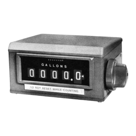
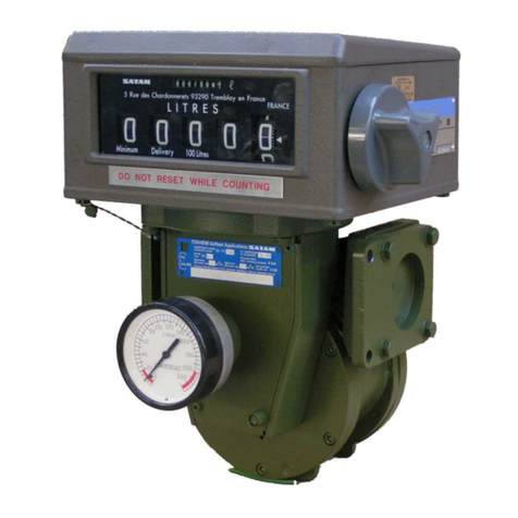
SATAM ZCM17 Instruction Manual

02/2018Edition1/19U518156‐en‐REV0
MASTERMETERDescription,Operation,Maintenance

02/2018Edition2/19U518156‐en‐REV0
AboutThisManual
Thisdocumentcontains19pages,includingthefrontpage.ThisdocumentisthepropertyofSATAM.
Itmaynotbedistributedtothirdpartieswithoutpriorauthorization.
SATAMreservestherighttomodifythisdocumentwithoutpriornotification.
ThisdocumentcomplieswiththecurrentEuropeanATEXDirective.
Revisionhistory
2018/02/09Rev0Creation
SupportandContactInformation
ServicedepartmentAvenuedeVerdunCS60129
Tel:+33(0)980800402
Email:[email protected]
ManufacturingfacilityAvenuedeVerdunCS60129
14700Falaise‐France
Tel:+33(0)231414141
Fax:+33(0)231407561
HeadquartersandSalesdepartmentParisNord2‐Bat.LeGauguin
47alléedesImpressionnistes
BP85012‐Villepinte
95931RoissyCharlesDeGaulleCedex–France
Tel:+33(0)148630211
Email:[email protected]
Websitewww.satam.eu

02/2018Edition3/19U518156‐en‐REV0
TableofContents
1.Functionalities.................................................................................................................................4
2.GeneralarrangementofZCM17.....................................................................................................4
A.Versionwithelectronicregister..................................................................................................4
B.Versionwithmechanicalregister................................................................................................5
3.MaincomponentsofZCM17mastermeter....................................................................................6
A.PositivedisplacementmeterZC17..............................................................................................6
B.ElectronicregisterEQUALISS......................................................................................................7
C.Mechanicalregister.....................................................................................................................8
D.Rateofflowindicator..................................................................................................................9
4.NarrativeDescription....................................................................................................................10
5.PeriodicServicing..........................................................................................................................10
6.Cleaning.........................................................................................................................................10
7.MeterCalibrationInspection–WeightandMeasures.................................................................11
A.AdjustmentProcedurewithtransmitterAB21.........................................................................11
B.AdjustmentProcedurewithEQUALISS.....................................................................................12
8.TechnicaldataofZCM17mastermeter.........................................................................................16
A.Technicaldata:ZCM17withmechanicalregister.....................................................................16
B.Technicaldata:ZCMwithelectronicregister............................................................................17
9.Dimensionsandweight(trolleyversion).......................................................................................19

02/2018Edition4/19U518156‐en‐REV0
1. Functionalities
SatammastermetersmodelZCM17arededicatedtoperiodiccalibrationofcustodytransfer
measuringequipmentforfuelsandpetroleumproducts.
ZCM17isaworkingstandardthatcanbeusedregularlytocheckandcalibratemeasuring
instrumentsormeasuringsystems.
2. GeneralarrangementofZCM17
A. Versionwithelectronicregister
Release
valve
Electronic
register
Pressure
gauge
Release
valve
Drainage
pump
Connecting
pipe
PD meter
Connection to
flexible hose

02/2018Edition5/19U518156‐en‐REV0
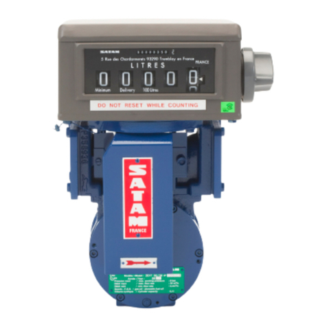
B. Versionwithmechanicalregister
*:optionalsupply
Isolating
valve (*) Release
valve
Temperature
probe (*)
Pressure
gauge
Mechanical
register
Drainage
pump
Release
valve
Flowrate
indicator
PD meter
Connection to
flexible hose
Connecting
pipe

02/2018Edition6/19U518156‐en‐REV0
3. MaincomponentsofZCM17mastermeter
SatamZCM17mastermeterconsistsofthefollowingcomponents
A. PositivedisplacementmeterZC17
ThemeasuringchamberofSatamZC17iscomposedof
‐Abody(1)madeupof2cylindricalparts(2)and(3)ofdifferentradii,connectedviacurvesin
suchawaythatthesumofthedistancesfromcentrepointOtotwopointsoppositeeach
otheronthestatorisconstant.
‐Amovingpart(4)composedofarotorturningonstainlesssteelballbearings(6),carbon
blades(7)linkedtoeachotherbyrods(8)and2steelcovers(9)and(10).
Measuringprinciple
Theproductentersthemeasuringchamberfollowingthe
directionofthearrow.Therotorandbladesassembly(1‐2)
issetinmotionbythepressureoftheliquidonblades.A
certainamountofliquid(3)isheldbetween2bladesand
thendirectedtothedischargemanifold.Thevolumeof
liquidmeasuredateachrotationisthereforeequalto4
timesthemeasuredquantity(3).Thesmoothcurvesthe
meterpiecesprovideasteady,non‐fluctuatingflow
resultinginlowheadloss.
Therotationoftherotoristransmittedmechanicallyeithertoapulsestransmitterincaseofadevice
fittedwithelectronicregisterortoanadjustingmechanismiscaseofadevicefittedwithmechanical
register.

02/2018Edition
7/19U518156‐en‐REV0
ForcompleteinformationaboutZC17operationpleaserefertofollowingtechnicalmanuals:
ReferenceTechnicalmanual
U508131Description,installation,operation,servicingforZC17‐24andZC17‐48
U508334Description,installation,operation,servicingforZC17‐80;ZC17‐150,ZC17‐250and
ZC17‐330
B. ElectronicregisterEQUALISS
TheEQUALISSFieldBatchControllerdepotversionisanintelligentelectronic
calculator/indicator,controlledbyseveralembeddedmicroprocessors,designedforefficient
managementoffluidmeasurement.Itcarriesoutthecalculation,displayandmanagementfunctions,
essentialtoproductloadingorunloading.
EQUALISisdesignedtobeusedinanexplosiveatmosphere,withdifferentprotectionmodes,in
accordancewithdirectiveATEX94/9/CE.
Itisdesignedtoensurethedatabackupofthecurrentdeliveriesintheeventofapowerfailure.This
dataisrestoredassoonasthepowersupplyisrestored.
TheEQUALISuserinterfaceincludesa240x128pixelbacklitgraphicdisplay,a20‐keykeyboardand
StopandStartbuttons.
TheelectronicindicatorSEQUALISdepotversionconsistsofahousingcomposedoftwoelements.It
islocatedattheloadingpoint.Itconsistsoftwoboxes:
‐TheCalculatorModule(CMmodule),
‐TheHydraulicModule(HMmodule)fortheoutputcontrol.
Theelectronicindicatorissuppliedwith230VACor24VDC,Itisequippedtocommunicatewith
externalsupervisionsystems.

02/2018Edition
8/19U518156‐en‐REV0
ThemainfeaturesoftheEQUALISSflowcomputerarethefollowing:
Graphicdisplay:AnyinformationnecessaryrequiredtousetheEQUALISSisdisplayedonasingle
screen,inawaythatisuser‐friendlyandinteractive.
Dustandwaterresistant:EQUALIShasbeendevelopedandmanufacturedinsuchawayastomake
itresistanttotherisksofeverydayuseandtheelements.
Adjustablemetercurve:TheEQUALIShasaparameterusedtocorrectthecurvebyreducingthe
counterto0‰measurementerroratoperationflowrate.Italsoprovidesthepossibilitytolinearize
thecurvebyusinganerrorcorrectionparameterin6sectors.
Harddiskmemory:Thetransactionsaswellasthesystem’sconfigurationandcalibrationparameters
arebacked‐upinasecuredatabase.Thecapacityofthismemoryallowstosaveupto50000
transactions.
EQUALISSalsoallowsconsultingandreprintingtransactionswhicharestoredinthisdatabase.The
metrologicaldatafeaturedonthisticketisrecognisedbylegalmetrologyauthorities.
Dualchannelsforpulses:EQUALISSmaybeconnectedto1or2pulsetransmitters.Where2pulse
transmittersareconnected,EQUALISSdisplaysthetotalvolumefromthesetwo2counters.
Systematicallyforthis(these)transmitter(s),theEQUALISScounts,storesandcomparesthetwo
pulsechannelsforeachtransmitterwithaphaseshiftof90°.Ifanydisparityisdetectedbetween
their2respectivepulsetrains,thedeliveryisstopped,thusalsopreventinglossofproductduetoa
defectivetransmitter.
ForcompleteinformationaboutEqualisSoperationpleaserefertofollowingtechnicalmanual:
ReferenceTechnicalmanual
U517478EqualisSInstallationmanual
U517504EqualisSProgrammingmanual
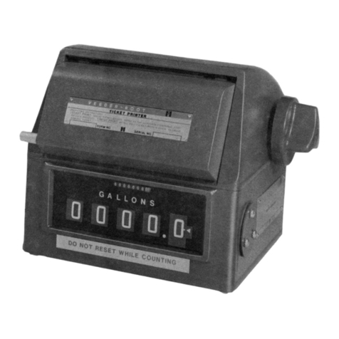
C. Mechanicalregister
Themechanicalregisterisamechanicalindicator.Itdisplaythe
measuredvolumeatoperatingconditions.Theresettablevolume
isdisplayedwith5digitsandthenon‐resettablevolumeis
displayedwith8digits.
Forcompleteinformationaboutmechanicalregisteroperationpleaserefertofollowingtechnical
manual:
ReferenceTechnicalmanual
U508218VR7887Description,installation,operation,servicing

02/2018Edition9/19U518156‐en‐REV0
D. Rateofflowindicator
EachZCM17isabletodisplaytheflowrateinL/minorinm3/h.
Whenfittedwithamechanicalregister,therateofflowindicatoris
anexternalmodulelocatedatthebottomoftheregister.The
physicalunitoftheflowmustbedefineattheorderofthemaster
meter.Whenfittedwithaelectronicregister,theflowratevalueis
directlydisplayedontheregisterwithouttheneedofany
additionalmodule.

02/2018Edition10/19U518156‐en‐REV0
4. NarrativeDescription
‐ConnectZCM17withhosebetweenthemeteringsystemtobetestedandthereceivingtank
‐StartadeliverytofilltheZCM17uptothetransferpoint
‐Resetthemechanicalhead/PuttheEqualisSindeliverymode
‐Startdeliverywithapresetvolume
‐Comparethevolumedisplayedbythemastermeterwiththeonedisplayedbythemeterto
betested
‐Adjustthemetercorrectioncoefficient
‐Startanewdeliverytoconfirmthecorrection
‐UsethedrainagehandpumptoemptytheZCM17tolimitpollutionwhendisconnectingor
testingwithanewfluid
‐DisconnecttheZCM17hose
5. PeriodicServicing
Asageneralrule,aperiodicmaintenanceofatleastonceayearisrecommended.
ServiceoperationsmustbecarriedoutbyaWeights&MeasuresapprovedCompany.
6. Cleaning
Westronglyadviseagainsttheuseofahighpressurewaterjettocleanthemeasuringunit,asthis
couldseriouslydamagethemeteringunit.

02/2018Edition
11/19U518156‐en‐REV0
7. MeterCalibrationInspection–WeightandMeasures
CurrentFrenchlegislationstipulates:
‐Metrologicalinspectionofthemeteratoperationstart‐up.
‐Thereafter,annualinspections.
A. AdjustmentProcedurewithtransmitterAB21
‐Unsealandremovecover(A)
‐Moveroller(5)byturningscrew(6)usingspanner"C"untiltherollerholeisaligned
withthe2holesonthesupport(15)
‐Insertpin(B)asshownonthediagram.
‐Turnthescrewright(clockwise)toincreasethequantityofproductinthegauge.
‐Turnthescrewleft(anticlockwise)todecreasethequantityofproductinthegauge.
‐Oneturnofthescrew(6)=Correctionof1‰
PinB=SATAMref.359809
SpannerC=SATAMref.359810
CAUTION : Do not omit to remove Pin "B" after adjustment.

02/2018Edition
12/19U518156‐en‐REV0
B. AdjustmentProcedurewithEQUALISS

02/2018Edition
13/19U518156‐en‐REV0

02/2018Edition
14/19U518156‐en‐REV0

02/2018Edition
15/19U518156‐en‐REV0

02/2018Edition16/19U518156‐en‐REV0
8. TechnicaldataofZCM17mastermeter
A. Technicaldata:ZCM17withmechanicalregister
Performance characteristics
Measured liquids Liquid hydrocarbons, industrial oil, fatty acid esters, ethanol
Static pressure max 15 bar
Inlet pressure max 10 bar
Liquid temperature min / max - 10°C / +90°C 14°F / +194°F
Working flow rate min / max
Model m3/h L/mn USGPM
ZCM17-24 2;4 / 24 40 / 400 10.5 / 105
ZCM17-48 4.8 / 48 80 / 800 21 / 210
ZCM17 - 80 8 / 80 133 / 1333 36 / 360
ZCM17-150 15 / 150 250 / 2500 66 / 660
ZCM17-250 25 / 250 416 / 4166 110 / 1100
ZCM17-330 33 / 330 550 / 5500 145 / 1453
Liquid viscosity max 20 mm²/s (MID) - 800 mm²/s - at operating conditions
Accuracy / Reapeatability < 0.1% of measured value / < 0.02% of measured value
Calibration report
According to OIML R117-1 / One calibration report per operating viscosity
Calibration at 7 flowrates with 2 repetitions per flow rate
Flowmeter manifold
Connection nominal size
Model Nominal size
ZCM17-24 DN50 / 2’’
ZCM17-48 DN50 / 2’’
ZCM17 - 80 DN80 / 3’’
ZCM17-150 DN100 / 4’’
ZCM17-250 DN150 / 6’’
ZCM17-330 DN200 / 8’’
End connection style Flanges ASA 150 RF
Coating Acrylic-Epoxy coating RAL5010, Marine Epoxy coating RAL5010 (option)
Flowmeter body
Body material Ductile iron (EN 5.3201) , Ni resist iron (EN-JL3011) (option)
Cap/end cover material Carbon steel (EN 1.0625) with protective coating
Seal/O-ring material Viton, Nitrile (option for alcohols measurement)
External coating Acrylic-Epoxy coating RAL5010, Marine Epoxy coating RAL5010 (option)
Measuring chamber
Displacement element type Sliding vanes flowmeter
Cyclic volume
Model L USG
ZCM17-24 0.4 0.1
ZCM17-48 0.8 0.21
ZCM17 - 80 2.27 0.6
ZCM17-150 4.54 1.12
ZCM17-250 6.82 1.8
ZCM17-330 9.09 2.4
Blades / Blades connection rods Graphite / Stainless steel
Rotor / Bearings Aluminum (EN AC-42100) / Stainless steel (EN 1.4301)
Swing joint Viton, Nitrile (option for alcohols), PTFE (option for low ambient temperature)
Drive train and adjuster
Drive type / Accuracy adjuster type Mechanical transmission / AB21
Register
Register type Mechanical register
Model / Accessories VR7887, 5 digits / Preset with valve, printer, pulses transmitter
Flowrate indicator
Display Indication in L/mn, option: m3/h, USGPM

02/2018Edition17/19U518156‐en‐REV0
Trolley version (option)
Trolley Calibration device mounted on chassis with 4 pivoting wheels
Connecting pipes between meter and hoses 2, Steel
Flexible hoses / Connections
3mL/ Loosetypeflanges ASA150lbs, TODOtypecouplings, CAMLOCKtypecouplings
Model Nominal size
ZCM17-24 DN50 / 2’’
ZCM17-48 DN50 / 2’’
ZCM17 - 80 DN80 / 3’’
ZCM17-150 DN100 / 4’’
ZCM17-250 DN150 / 6’’
ZCM17-330 DN200 / 8’’
Isolating valve Ball valve located downstream the meter (option)
Drainage equipment Manual drainage pump with purge valve, hoses and 2 release valves
Accessories
Temperature measurement Local display (option)
Pressure measurement Local display
Environmental
Ambient working temperature min / max -25°C, -40°C (option) / +55°C -13°F, -40°F (option) / +131°F
Storage temperature min / max -40°C / +80°C -40°F / +176°F
Certification
ATEX Zone 1 II 2 G
B. Technicaldata:ZCMwithelectronicregister
Performance characteristics
Measured liquids Liquid hydrocarbons, industrial oil, fatty acid esters, ethanol
Static pressure max 15 bar
Inlet pressure max 10 bar
Liquid temperature min / max - 10°C / +90°C 14°F / +194°F
Working flow rate min / max
Model m3/h L/mn USGPM
ZCM17-24 2;4 / 24 40 / 400 10.5 / 105
ZCM17-48 4.8 / 48 80 / 800 21 / 210
ZCM17 - 80 8 / 80 133 / 1333 36 / 360
ZCM17-150 15 / 150 250 / 2500 66 / 660
ZCM17-250 25 / 250 416 / 4166 110 / 1100
ZCM17-330 33 / 330 550 / 5500 145 / 1453
Liquid viscosity max 20 mm²/s (MID) - 800 mm²/s - at operating conditions
Accuracy / Repeatability < 0.1% of measured value / < 0.02% of measured value
Calibration report
According to OIML R117-1 / One calibration report per operating viscosity
Calibration at 7 flowrates with 2 repetitions per flow rate
Flowmeter manifold
Connection nominal size
Model Nominal size
ZCM17-24 DN50 / 2’’
ZCM17-48 DN50 / 2’’
ZCM17 - 80 DN80 / 3’’
ZCM17-150 DN100 / 4’’
ZCM17-250 DN150 / 6’’
ZCM17-330 DN200 / 8’’
End connection style Flanges ASA 150 RF
Coating Acrylic-Epoxy coating RAL5010, Marine Epoxy coating RAL5010 (option)
Flowmeter body
Body material Ductile iron (EN 5.3201) , Ni resist iron (EN-JL3011) (option)
Cap/end cover material Carbon steel (EN 1.0625) with protective coating
Seal/O-ring material Viton, Nitrile (option for alcohols measurement)
External coating Acrylic-Epoxy coating RAL5010, Marine Epoxy coating RAL5010 (option)

02/2018Edition18/19U518156‐en‐REV0
Measuring chamber
Displacement element type Sliding vanes flowmeter
Cyclic volume
Model L USG
ZCM17-24 0.4 0.1
ZCM17-48 0.8 0.21
ZCM17 - 80 2.27 0.6
ZCM17-150 4.54 1.12
ZCM17-250 6.82 1.8
ZCM17-330 9.09 2.4
Blades / Blades connection rods Graphite / Stainless steel
Rotor / Bearings Aluminum (EN AC-42100) / Stainless steel (EN 1.4301)
Swing joint Viton, Nitrile (option for alcohols), PTFE (option for low ambient temperature)
Drive train and adjuster
Drive type Mechanical transmission
Accuracy adjuster type Calibration constants – Linearization according to calibration report
Pulses transmitter Type AC30
Register
Register type
Display Operating volume, base volume, volume flowrate, temperature
Accessories
Temperature measurement Pt100
Pressure measurement Local display
Trolley version (option)
Trolley Calibration device mounted on chassis with 4 pivoting wheels
Connecting pipes between meter and hoses 2, Steel
Flexible hoses / Connections
3mL/ LoosetypeflangesASA 150lbs,TODO typecouplings,CAMLOCK typecouplings
Model Nominal size
ZCM17-24 DN50 / 2’’
ZCM17-48 DN50 / 2’’
ZCM17 - 80 DN100 / 4’’
ZCM17-150 DN100 / 4’’
ZCM17-250 DN150 / 6’’
ZCM17-330 DN200 / 8’’
Isolating valve Ball valve located downstream the meter (option)
Drainage equipment Manual drainage pump with purge valve, hoses and 2 release valves
Environmental
Ambient working temperature min / max -25°C, -40°C (option) / +55°C -13°F, -40°F (option) / +131°F
Storage temperature min / max -40°C / +80°C -40°F / +176°F
Certification
ATEX Zone 1, II 2 G – See note 1

02/2018Edition19/19U518156‐en‐REV0
9. Dimensionsandweight(trolleyversion)
Hoses for process connection are not shown on this drawing.
Dimensions (mm) ZCM17-24 ZCM17-48 ZCM17-80 ZCM17-150 ZCM17-250 ZCM17-330
A 600 600 1100 1100 1400
Please
contact
Satam for
dimensions
and weight
B 1100 1100 1199 1250 1200
C 1050 1050 1419 1419 1800
D 520 520 520 560 700
E 870 870 870 920 980
Weight (kg) 218 230 300 300 450
A
E
B
C
D
Table of contents
Other SATAM Measuring Instrument manuals
Popular Measuring Instrument manuals by other brands

PCB Piezotronics
PCB Piezotronics IMI SENSORS 623C00 Installation and operating manual

Laserworld
Laserworld Ecoline Series manual

PDK
PDK PDR100 user manual

Thermo Scientific
Thermo Scientific AQUAfast AQ3140 COD user guide

Fluid Components Intl
Fluid Components Intl ST51A Installation, Operation & Maintenance Instruction Manual

SensorLink
SensorLink True RMS Ampstik 8-020 Operator's manual