Venture Industries VMS ATEX Product guide

USER MANUAL No. 08212019-EN/01 (ENG)
VALID SINCE 08.01.2019
OPERATING AND ASSEMBLY INSTRUCTIONS
VIBRATION MONITORING SYSTEM
VMS ATEX
Venture Industries Sp. z o.o. is not responsible for any damage caused by improper use of the fan and reserves the right to modify this document
without informing the user.
Venture Industries Sp. z o.o. http://www.venture.pl Tel. (0-22) 7519550; 7512031
05-092 Łomianki-Kiełpin, Polska

page 2
tel. (0-22) 7519550; 7512031, fax (0-22) 7512259; 7511202, e-mail: venture@venture.pl
Table of Contents
1. INTRODUCTION ......................................................................................................................................................... 3
2. TECHNICAL DATA OF THE SYSTEM ........................................................................................................................ 3
3. INSTALLATION ....................................................................................................................................................... 4
A. Mounting the sensor ......................................................................................................................................... 4
B. Connecting the power supply ........................................................................................................................... 4
C. Motor connection diagram ............................................................................................................................... 5
4. STARTING .............................................................................................................................................................. 5
5. OPERATION AND EXPLOITATION .......................................................................................................................... 6
A. Measurement ................................................................................................................................................... 6
B. Test of periodic functions ................................................................................................................................. 6
C. Detection of vibrations ..................................................................................................................................... 6
D. Detection of too high temperature .................................................................................................................. 6
E. Housing - buttons and controls......................................................................................................................... 8

page 3
tel. (0-22) 7519550; 7512031, fax (0-22) 7512259; 7511202, e-mail: venture@venture.pl
1. INTRODUCTION
The VMS system is intended for continuous monitoring of fan parameters (Vibrations,
temperature of the motor windings). VMS allows measurement of signals from 1 vibration sensor
in ATEX execution for zones 1 and 21, maintaining the security integrity level SIL1.
The automatic box has been designed for installation in a safe zone.
Standard system uses two sensor NC contacts, one contact oversees the safety relay, while
the second activates the interface relay with information on exceeding the first alarm threshold.
The system has been equipped with a PTC relay (for ATEX zones) to which should be connected a
signal from PTC sensors located in the motor winding. An additional option of the system is the
ability to read vibration values (4-20mA analog signal).
2. TECHNICAL DATA OF THE SYSTEM
Power 230VAC, 50/60Hz
Current max. 1,5 A
Overcurrent protections Type C, 2A
Sensor
Vibration range 0-16 mm/s Vrms
Ambient temperature -30°C…+60°C
Measurement range 10 Hz...1000 Hz
Output signals 1 x 4…20mA, 2 x relay contact
IP 67
IP housing 54
page 4
tel. (0-22) 7519550; 7512031, fax (0-22) 7512259; 7511202, e-mail: venture@venture.pl
3. INSTALLATION
The delivered system is ready for use. All you need to do is do the following:
- connect power contactors supplying the fan in accordance with a diagram,
- connect the power supply (according to the provided diagram),
- set the sensor's vibration thresholds.
The device may only be installed by qualified and authorized personnel (with appropriate
qualifications), in accordance with health and safety rules, relevant legal regulations in
force in Poland and the instruction manual of the device.
The cable from the sensor should be placed in such a way that it will not be exposed to
mechanical damage.
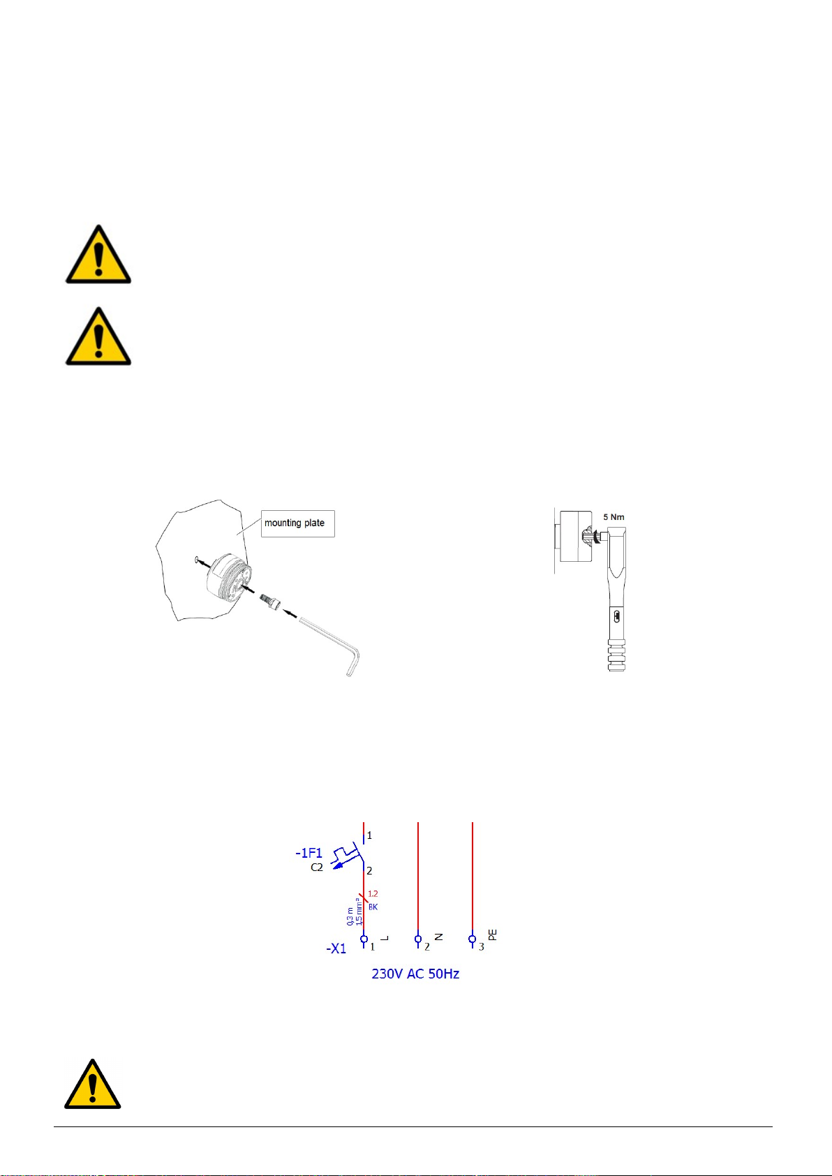
A. Mounting the sensor
Mounting the sensor is done by screwing to the appropriate surface with the M8 screw. The
housing cover should be tightened with a torque wrench.
Fig. 1 (sensor connection)
B. Connecting the power supply
Fig. 2 (Some of the electrical documentation)
ATTENTION!
Although the overcurrent switch is turned off, there may still be voltage in the
cabinet.
page 5
tel. (0-22) 7519550; 7512031, fax (0-22) 7512259; 7511202, e-mail: venture@venture.pl
C. Motor connection diagram
Fig. 3 (Motor connection - according to electrical documentation)
4. START-UP
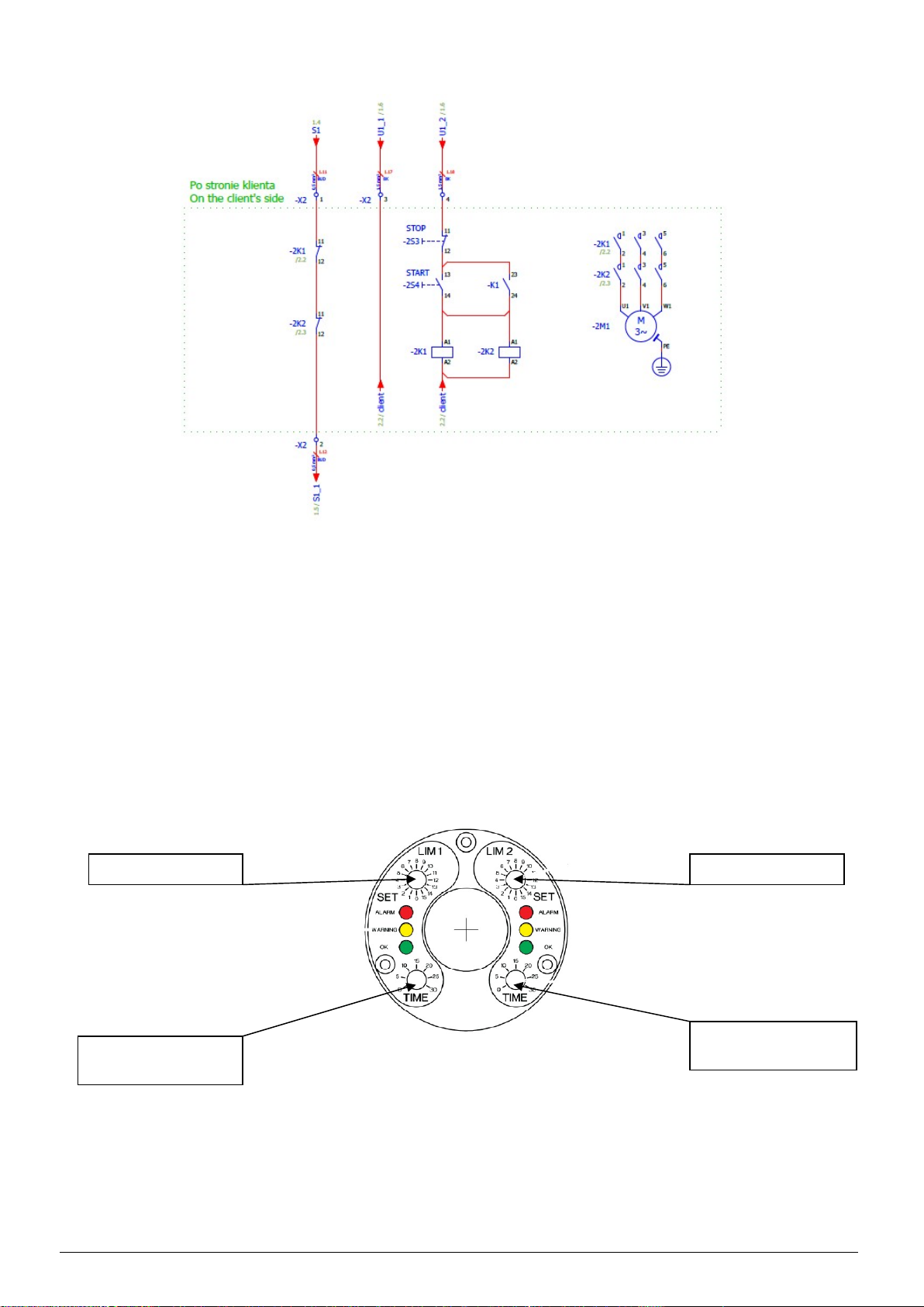
After properly tightening the sensor and setting the appropriate vibration range setting
(table included in the fan operation and installation manual) using the knobs on the sensor (Fig.4).
As well as after the correct electrical installation we can start supplying power to the VMS system.
At the first start-up, the system is in the state of passivation (safety relay in the state of
opening control contacts, the RESET button lights up in blue), for the system to be reactivated,
press the RESET button. The transition to the state of reactivation of the system will be confirmed
by switching off the blue diode.
Fig. 4 (Setting of sensor ranges)
Off value Value of the warning
Delay time,
recommended value 0
Delay time,
recommended value 0
Table of contents


