manuals.online logo
Brands
  1. Home
  2. •
  3. Brands
  4. •
  5. Venturo
  6. •
  7. Construction Equipment
  8. •
  9. Venturo HT25KX Operating instructions

Venturo HT25KX Operating instructions

20594
2-14-03A
6-4-03B
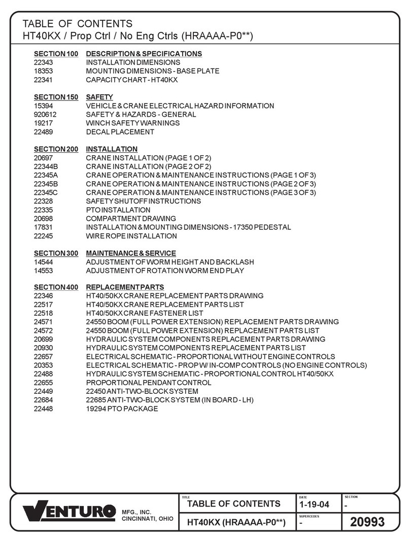
TABLE OF CONTENTS
HT25KX (HLAAAB-00**)
SUPERCEDES
TITLE DATE SECTION
TABLE OF CONTENTS
HT25KX / Std Ctrl / No Eng Ctrls (HLAAAB-00**)
SECTION 100 DESCRIPTION & SPECIFICATIONS
19801 INSTALLATIONDIMENSIONS
19930 BASE MOUNTING DIMENSIONS
I19233 CAPACITY CHART - HT25KX
I19288 SERVICE BODY REINFORCEMENT
14510 FLAT BED REINFORCEMENT
SECTION 150 SAFETY
15394 VEHICLE & CRANE ELECTRICAL HAZARD INFORMATION
920612 SAFETY & HAZARDS - GENERAL
I19217 WINCH SAFETY WARNINGS
20346 DECAL PLACEMENT
SECTION 200 INSTALLATION
I19212A CRANE INSTALLATION (PAGE 1 OF 2)
I19212B CRANE INSTALLATION (PAGE 2 OF 2)
20435A CRANE OPERATION & MAINTENANCE INSTRUCTIONS (PAGE 1 OF 2)
20435B CRANE OPERATION & MAINTENANCE INSTRUCTIONS (PAGE 2 OF 2)
22328 SAFETY SHUTOFF INSTRUCTIONS
I19232 PTOINSTALLATION
I19213 COMPARTMENT DRAWING
22245 WIRE ROPE INSTALLATION
20453 IN-COMPARTMENTCONTROLSINSTALLATION
20415A RADIO INSTALLATION & OPERATION INSTRUCTIONS - RADIO REMOTE (PAGE 1 OF 2)
20415B RADIO INSTALLATION & OPERATION INSTRUCTIONS - RADIO REMOTE (PAGE 2 OF 2)
20416 RADIOOPERATIONINSTRUCTIONS
SECTION 300 MAINTENANCE & SERVICE
20531 LUBRICATION & MAINTENANCE CHART
SECTION 400 REPLACEMENTPARTS
19910 HT25KX CRANE REPLACEMENT PARTS DRAWING
19911 HT25KX CRANE REPLACEMENT PARTS LIST
19944 HT25KX CRANE FASTENER LIST
19996 19950 BOOM REPLACEMENT PARTS DRAWING
20197-2 ANTI-TWO-BLOCK REPLACEMENT PARTS DRAWING
20360 ELECTRICAL SCHEMATIC - STANDARD (NON-PROPORTIONAL)
20350 ELECTRICAL SCHEMATIC - NON-PROP W/IN-COMP CONTROLS
20534 HYDRAULIC SYSTEM COMPONENTS REPLACEMENT PARTS DRAWING
19496 HYDRAULIC SYSTEM DIAGRAM - HT25KX
20278 20172 PENDANT REPLACEMENT PARTS DRAWING
20417 RADIO REMOTE REPLACEMENT PARTS DRAWING
I19249 19830-1 ELEVATION CYLINDER DRAWING
19908 19886-1 EXTENSION CYLINDER DRAWING
22448 19294 PTO PACKAGE
CINCINNATI, OHIO
MFG., INC. -

SECTION 100
DESCRIPTION
&
SPECIFICATIONS
7607100A
16"
14"
10"
16"
35"
9-1/2"
11-3/4"
18 FT
21 3/4 FT
12 1/4 FT
4FT
43/4"
8"
6FT
SNATCHBLOCKFOR
TWOPARTLINEOPERATION
5/16"DIAWIREROPE
75FTLONG
HEADACHE
BALL
HOOKWITH
SAFETYLATCH
BOOMANGLEANDCAPACITY
INDICATORONBOTHSIDES
OFBOOM
TOTALINSTALLED
WEIGHT1350lbs.
BASEMOUNTING
DIMENSIONS
WARNING:THESEPRODUCTS
ARENOTPASSENGERLIFTS.
THEYARENOTDESIGNEDOR
INTENDEDTOBEUSEDTO
LIFT,SUPPORT,OROTHERWISE
TRANSPORTPERSONNEL
MANUAL
POWER
3"DIA
R20-1/4"
SWING
RADIUS
16"15"
3"
1"
16"
10"REF
14"REF
Ø13/16"8PLC
1"
BASEMOUNTINGDIM
CINCINNATI,OHIO
MFG.,INC.
C200
19930
Ø3"
14"
REF
3"
10"
REF
ET/HT18K(X)&ET/HT25K(X)BASE
MOUNTINGDIMENSION
ET/HT18K(X)ET/HT25K(X)5-21-03A
7-29-03B
16"MIN/19"MAX
HOLESFOR3/4"
MOUNTINGBOLTS
5"DIA.HOLEFOR
HYD./ELEC
CONNECTIONS
SECTIONA-A
16"x16"MIN
COMPARTMENT
SPACE
SECTIONB-B
TRUCKFRAME
28"MIN
AA
B
B
5
4
3
7
2
5
1
8
4
2
7
3
6
ITISTHESOLERESPONSIBILITYOFTHEINSTALLERTO
INSURETHATTHETOTALSTRUCTUREOFCRANE,TRUCK,
ANDOUTRIGGERSARESTRUCTURALLYSOUNDANDTHAT
THECOMPLETEDVEHICLEHASSUFFICIENTSTABILITY
AGAINSTOVERTURNING.
TOPPLATE
CORNERPOST
CROSSFRAME
SHEARWEB
GUSSET
1
2
3
4
5
6
7
8BODYTOP
REINFORCEMENT
TOPPLATE
REINFORCEMENT
OUTRIGGERREIN-
FORCEMENTPLATE
PARTDESCRIPTIONMINIMUMRECOMMENDEDMATERIALSIZE
3"x3"x1/2"STEELANGLE
4"x4"x5/16"SQUARETUBING
3/16"STEELPLATE
1/2"x6"OR3/4"x5"STEELBAR
1/4"THICKSTEELPLATE
1/2"x4"H.R.STEEL
1/2"STEEL
TYPICALSERVICEBODYREINFORCEMENT
INSTALLATIONDWG
ET/HT25K(X)&ET/HT18K(X)
C100
10-11-02C
7-29-03D
SECTION
DATE
SUPERSEDES
10GASMOOTHORDIAMONDPLATEWITH
1"LIPOVERSIDEOFBODY
14510
C100
10-11-02L
7-29-03M
INSTALLATION DRAWING
ET/HT18K(X), ET/HT25K(X)
SUPERCEDES
TITLE DATE SECTION
CINCINNATI, OHIO
MANUFACTURING, INC.
5" HOLE FOR HYDRAULIC / ELECTRIC
CONNECTIONS - ET/HT18K(X), ET/HT25K(X)
SECTION 150
SAFETY
8604150
15394
C150
5-13-97G
5-15-02H
INSTALLATION DWG
ET & HT CRANE SERIES SUPERCEDES
TITLE DATE SECTION
VEHICLE & CRANE MOUNTED ELECTRICAL HAZARD SIGN
APPLICATION & INFORMATION
ET & HT CRANE SERIES
SIGN NO. 15393A DISPLAYS THE INTERNATIONAL SYMBOL FOR
ELECTRICITY AND WARNS OF DANGER FROM AN
ELECTRICALLY CHARGED VEHICLE, CRANE, OR LOAD. FOUR
ARE RECOMMENDED (ONE FOR EACH SIDE AND ONE FOR
EACH END OF VEHICLE) TO BE APPLIED IN LOCATIONS WHICH
ARE READILY VISIBLE TO GROUND PERSONNEL.
SIGN NO. 15401 PROVIDES ADDITIONAL WARNING OF LEGAL
REQUIREMENTS WHEN OPERATING NEAR HIGH VOLTAGE
LINES. THIS SIGN IS PLACED ON THE CONTROL PENDANT
SIDE OF BOOM.
REQUIRED MINIMUM CLEARANCES REFERRED TO ON SIGN NO. 15401
REQUIRED CLEARANCES FROM OVERHEAD HIGH-VOLTAGE LINES
NOMINAL VOLTAGE (kV) MINIMUM REQUIRED
(PHASE TO PHASE) CLEARANCE (FEET) *
0 - 50 10
over 50 - 200 15
over 200 - 350 20
over 350 - 500 25
over 500 - 750 35
over 750 - 1000 45
REQUIRED CLEARANCES FROM ENERGIZED HIGH-VOLTAGE CONDUCTORS
(WHILE IN TRANSIT)
NOMINAL VOLTAGE (kV) MINIMUM REQUIRED
(PHASE TO PHASE) CLEARANCE (FEET) *
0 - 0.75 4
over 0.75 - 50 6
over 50 - 345 10
over 345 - 750 16
over 750 - 1000 20
* NOTE: ENVIRONMENTAL CONDITIONS SUCH AS FOG, SMOKE, OR PRECIPITATION MAY REQUIRE
INCREASED CLEARANCES
CINCINNATI, OHIO
MFG., INC.
CRANE SAFETY AND HAZARDS
HT25KX, HT40KX, HT50KX
CAUTIONS
1. INSPECT VEHICLE AND CRANE, INCLUDING OPERATION, PRIOR TO USE DAILY.
2. DO NOT USE THIS EQUIPMENT EXCEPT ON SOLID, LEVEL SURFACE WITH CRANE MOUNTED ON
FACTORY-RECOMMENDED TRUCK.
3. BEFORE OPERATING THE CRANE, REFER TO MAXIMUM LOAD (CAPACITY) CHART ON CRANE FOR
OPERATING (LOAD) LIMITATIONS.
4. DO NOT OPERATE, WALK, OR STAND BENEATH BOOM OR A SUSPENDED LOAD.
5. ATTACH PENDANT CORD SUPPORT SNAP TO ATTACHMENT POINT BEFORE PLUGGING IN
PENDANT.
6. UNPLUG PENDANT AND DISENGAGE PTO SYSTEM WHEN CRANE NOT IN USE.
7. FOR TRAVEL, BOOM MUST BE IN STOWED POSITION.
DANGER
• THIS CRANE IS NOT A PASSENGER LIFT
• IT IS NOT DESIGNED OR INTENDED TO BE USED TO LIFT, SUPPORT, OR OTHERWISE TRANSPORT
PERSONNEL.
YOU MUST NOT OPERATE THIS CRANE UNLESS
1. YOU HAVE BEEN TRAINED IN THE SAFE OPERATION OF THIS CRANE
AND
2. YOU KNOW AND FOLLOW THE SAFETY AND OPERATING RECOMMENDATIONS CONTAINED IN THE
MANUFACTURER'S MANUALS, YOUR EMPLOYER'S WORK RULES, AND APPLICABLE GOVERNMENT
REGULATIONS. AN UNTRAINED OPERATOR SUBJECTS HIMSELF AND OTHERS TO DEATH OR
SERIOUS INJURY.
ELECTROCUTION HAZARD
• THIS MACHINE IS NOT INSULATED.
• MAINTAIN SAFE CLEARANCES FROM ELECTRICAL LINES AND APPARATUS.
• YOU MUST ALLOW FOR BOOM SWAY, ROCK OR SAG, AND ELECTRICAL LINE AND LOADLINE
SWAYING.
• THIS LIFTING DEVICE DOES NOT PROVIDE PROTECTION FROM CONTACT WITH OR PROXIMITY TO
AN ELECTRICALLY CHARGED CONDUCTOR.
• YOU MUST MAINTAIN A CLEARANCE OF AT LEAST 10 FEET BETWEEN ANY PART OF THE CRANE,
LOADLINE, OR LOAD, AND ANY ELECTRICAL LINE OR APPARATUS CARRYING UP TO 50,000 VOLTS.
ADDITIONAL CLEARANCE IS REQUIRED FOR VOLTAGES IN EXCESS OF 50,000 VOLTS. REFER TO
DRAWING 15394 FOR ADDITIONAL INFORMATION.
•DEATH OR SERIOUS INJURY WILL RESULT FROM CONTACT OR INADEQUATE CLEARANCE.
920612
C150
6-12-92
5-13-97A
INSTALLATION DWG
HYDRAULIC CRANES SUPERCEDES
TITLE DATE SECTION
CINCINNATI,OHIO
MFG., INC.
I19217
C150
10-17-97A
5-26-98B
INSTALLATION DWG
HT CRANES SUPERCEDES
TITLE DATE SECTION
WINCH SAFETY WARNINGS
CINCINNATI, OHIO
MFG., INC.
BOOM
22496
LARGE
VENTURO
15401
UNLAWFUL
TO OPERATE
CAPACITY
DECAL MODEL PART NO.
RIGHT
LEFT
19257-1
19257-2HT25K(X)
19788
PROPORTIONAL CONTROL
* PROPORTIONAL ONLY
LEFT
15392
DANGER
ELEC.
HAZARD
BACK
15390
CAUTION
15391
DANGER
(NOT
PASSENGER
LIFT)
19314-2
MANUAL
OVERRIDE
RIGHT
14473-2
GREASE
TOP
14473-2
GREASE
19745
HT25KX
HT25K(X)
SHUT OFF DECAL
19315-1
19315-2
MANUAL
PROPORTIONAL
19314-1
MANUAL
OVERRIDE
SECTION 200
INSTALLATION
7607200A
I19212a
C200
8-12-99C
6-17-02D
INSTALLATION DWG
HT25KX SUPERCEDES
TITLE DATE SECTION
CRANE INSTALLATION
HT25KX
BODY REINFORCEMENT
Thetruckbodymustbereinforcedandoutriggersprovidedtowithstandthecombinedloads
resultingfromliftingandtheweightofthecraneandboom.
ThemaximumcombinedoverturningmomentfortheHT25KXis27,000ft.lbs.
Themaximumverticalloadis6500lbs.
CRANE MOUNTING
Thecranebaseplateormountingpedestalmustbeboltedtothebodyreinforcingplatewith
eight (8) grade five (5) bolts of 3/4" dia. with either coarse or fine threads. A 4.5" dia. hose
clearanceholemustbecutinthisplatetoallowthehosestoswingandcoilfreely.
ROTATION POSITIONING
TheHTcranesareshippedwiththeboomrotatedtothemiddleofthe 400 degree rotation
travellimit. Thelocationofthismiddlepositionrelativetothecenterlineofthetruckmustbe
decidedpriorto mounting. It can be inanypositionthatpleases the users sincetheboomcan
alwaysreachthestorageandtravelpositionbyrotatingonewayortheother.
HYDRAULIC CONNECTIONS
Thecraneisfurnishedwithapressureandareturnhosethatcomedownthroughthecenterof
thehousing. Thesehosesaretobe arrangedin thecompartmentorpedestalbelowthecrane
asshownondrawingI19213usingtheanglebulkheadfittingsfurnishedintheinstallationkit.
Thesehosesare to beconnectedinarelaxed position asshownonI19213,while the craneis
at the midpoint of the 400 degree rotation range as received -- regardless of the final position
oftheboomduringstorage/travel.
Thebulkheadfittingsmaybelocatedonanysideofthecompartmentrelativetothemiddleof
rotationposition.
Thecranepressureandreturnhoseshave differentsizesofSAE37degreeflareswivel
fittings. Thesmallerswivelisonthepressurehosewhichhasa3/8flare. Thelargerswivelis
onthereturnhosewhichhasa1/2flare.
CINCINNATI,OHIO
MFG., INC.
I19212b
C200
4-24-02D
6-17-02E
INSTALLATION DWG
HT25KX SUPERCEDES
TITLE DATE SECTION
ELECTRICAL CONNECTIONS
A25ft. electrical power lead -intendedfor12VDC only - alsocomesdownthroughthe center
ofthehousingwiththehoses. Thisleadshouldbeloopedinthecompartmentsothat itre-
mainsrelaxedthroughoutthe400degreerotationofthecrane.
A15amp circuitbreakeris mountedonthe craneandprotectsthecrane'sinternalwiringand
solenoid coils. The 15amp circuit breaker does not protect the 25 foot electrical power lead.
For added protection, the 25 ft. lead can be connected to a 15-20 amp protected circuit that, if
possible,ispoweredonlywhenthevehicleengineisrunning
HYDRAULIC FLUID
AverageClimate TypeofOil
Cold to Moderate ISO Grade AW 46
Warmto Hot ISO Grade AW 68
Thefluidshouldhavethehighestanti-wearcharacteristicsandtreatedtoinhibitrustand
oxidation.
HYDRAULIC HOSES & LINES
Theminimumsizesforlinesandhosesareasfollows:
PRESSURE 1/4"
RETURN 3/8"
SUCTION 3/4"
RESERVOIR
ThePTOreservoirshouldhaveacapacityof8gallonsfittedwith100meshsuctionscreen,10
micronreturnlinefilter,andfiller/breathercap.
PTO PUMP
Forstandard(non-proportional)cranes,thePTOpumpshouldbesizedtoprovide2.0gpm(or
1.5 gpm for more delicate control of loads) at 3000 psi when engine is at desired idle speed.
Forproportionalcranes, the PTO pump should be sized to provide 4.0 gpmat 3000 psi when
engine is at desired idle speed.
PTO START-UP
BeforeconnectingthePTOsystemtothecranepressureandreturnhoses,connectthePTO
pressureandreturnlinestogetheratthebulkhead. OperatethePTOsystemforabouttwo(2)
minutespergallonofreservoircapacity(inthiscase16minutes)toflushoutthelinesandfilter
allthefluidseveraltimes.
ENGINE START/STOP & THROTTLE CONTROL
Ifyourcranewaspurchasedwithoptionalenginestart/stopandthrottlecontrol,refertodrawing
22615inthereplacementpartssectionforfurtherinformation.
CINCINNATI,OHIO
MFG., INC.
SUPERCEDES
TITLE DATE SECTION
CINCINNATI, OHIO
MFG., INC.
CRANE OPERATION AND MAINTENANCE INSTRUCTIONS
HT25KX
SAFETY
Before operating this crane, read and understand these instructions, the 920612 Crane Safety and
Hazards Information Sheet, and review all safety & instruction labels on the crane.
CRANE INSPECTION
Before operating this crane, inspect for wear, damage, or oil leakage. After the wire rope has been run
out, check for wear, kinks, and broken strands. Check the hook and safety latch for damage. Correct
any problems before using the crane.
CAPACITY
Before operating this crane, review the capacity charts on the sides of the boom to relate the load to be
lifted to the boom length and angle. The boom angle is shown by a gravity arrow.
SNATCH BLOCK
If the load exceeds 2500 lbs. or reduced winching speed for better control of smaller loads is required,
use the snatch block to rig the crane for two part line operation.
CONTROLS
This crane is operated by a remote control pendant. The pendant should be unplugged and stored in a
compartment when the crane is not in use.
Before plugging the pendant in, inspect the plug, socket, cord, pendant head, and switches for damage.
Actuate all four switches both ways to verify that they all have the same feel and sound and that they
return to the center position.
PTO SYSTEM
Check the hydraulic fluid level in the PTO system reservoir. Engage PTO and set the engine idle speed
to provide a hydraulic flow rate per the PTO system instructions. A lower idle setting may be used for
more delicate spotting of loads if required.
CRANE OPERATION
Use "Winch Down" to release tension on the wire rope to unhook it from the storage tie down position.
Use "Boom Up" to elevate the boom from the boom rest position.
Avoid repeated rapid reversals of the control switches. This can cause the load to swing.
Check all control functions to see that they are working as described in the following section
CONTROL FUNCTIONS
WINCH "UP" and "DOWN" - Raises and lowers the load with the winch.
BOOM "UP" and "DOWN" - Raises and lowers the boom elevation angle. The boom elevates from 8
degrees below horizontal to 75 degrees above horizontal.
BOOM "OUT" and "IN" - Extends and retracts the boom. The boom hydraulic extension stroke is 6 ft.
20435A
C200
-
6-17-02
INSTALLATION DWG
HT25KX
SUPERCEDES
TITLE DATE SECTION
CINCINNATI, OHIO
MFG., INC.
20435B
C200
-
6-17-02
INSTALLATION DWG
HT25KX
ROTATION "L" and "R" - Controls the left and right direction of the crane rotation. The crane rotation
is limited to 400 degrees.
POWER (Non Proportional Systems with Engine Controls) - Energizes safety shutoff valve. See
page 22328 for detailed operating instructions and warnings.
TRIGGER (Proportional Systems Only) - Varies the flow rate delivered to the crane valve. The
farther the trigger is pulled, the faster the selected crane function operates.
OVERLOAD SENSING SYSTEM
This crane is equipped with an Overload Sensing System. If the capacity of the crane is exceeded,
the "Winch Up", "Boom Down", and "Boom Out" functions will be shut down. The "Winch Down",
"Boom Up", and "Boom In" functions will continue to operate and can be used to relieve the overload
condition. The "Rotation" function also will continue to operate.
The Overload system is inoperative if the boom elevation is at the bottom or top limit of travel. To
relieve this condition, raise or lower the boom slightly before lifting the load.
TWO-BLOCK SENSING SYSTEM
This crane is equipped with an anti two-block device that is mounted at the tip of the boom. If the
snatch block/overhaul weight contacts the device the "Winch Up", "Boom Down", and "Boom Out"
functions are disabled. The "Winch Down", "Boom Up", and "Boom In" functions will continue to
operate and can be used to relieve the two-block condition. Refer to Drawing 19050 for parts
breakdown and configuration information.
MANUAL TELESCOPIC BOOM
The 10 to 20 ft. boom has a 4 ft. manual telescoping section in addition to the 6 ft. power extension.
A pin locks the manual extension into either the extended or retracted position.
TRUCK SETUP & OUTRIGGERS
1. The truck should be parked on ground that is as level and as firm as possible when using the
crane.
2. The center of the crane should be positioned close enough to the job so that it can be operated at
a reach that puts the load within the rated capacity of the crane.
3. Set the vehicle parking brake and put the vehicle transmission in "park" if it is an automatic.
4. Deploy the outriggers to help stabilize the vehicle against rocking or overturning when lifting with
the crane.
PREPARATION FOR TRAVEL
1. Return the outriggers to the stowed position. Install and secure all pins.
2. Stow the crane boom in the boom support.
3. Hook the winch line to the tie down point on the boom and apply light tension.
4. Disengage the PTO pump and idle speed control.
5. Unplug the control pendant and store in a body compartment or the cab.

Other Venturo Construction Equipment manuals

Venturo HT45KX-25 User manual

Venturo

Venturo HT45KX-25 User manual

Venturo ET12KXP-16 User manual

Venturo

Venturo ET12KXP-16 User manual

Venturo ET16K 16 Series User manual

Venturo

Venturo ET16K 16 Series User manual

Venturo CT310KX(P) User manual

Venturo

Venturo CT310KX(P) User manual

Venturo HT30KX-25 User manual

Venturo

Venturo HT30KX-25 User manual

Venturo ET16KXX-20 User manual

Venturo

Venturo ET16KXX-20 User manual

Venturo HT40KXXP-20 User manual

Venturo

Venturo HT40KXXP-20 User manual

Venturo ET18KX-16 User manual

Venturo

Venturo ET18KX-16 User manual

Venturo ET30KX User manual

Venturo

Venturo ET30KX User manual

Venturo ET12KP-16 User manual

Venturo

Venturo ET12KP-16 User manual

Venturo ET8KP User manual

Venturo

Venturo ET8KP User manual

Venturo VC1000 Installation instructions

Venturo

Venturo VC1000 Installation instructions

Venturo ET18K-20 Series User manual

Venturo

Venturo ET18K-20 Series User manual

Venturo ET18KXXP-20 User manual

Venturo

Venturo ET18KXXP-20 User manual

Venturo 25100 User manual

Venturo

Venturo 25100 User manual

Venturo ET8K Operating instructions

Venturo

Venturo ET8K Operating instructions

Venturo HT40KX User manual

Venturo

Venturo HT40KX User manual

Venturo ET25KX User manual

Venturo

Venturo ET25KX User manual

Venturo ET16KX-16 User manual

Venturo

Venturo ET16KX-16 User manual

Venturo ET36KXX User manual

Venturo

Venturo ET36KXX User manual

Venturo HT66KX-25 VLC Operating instructions

Venturo

Venturo HT66KX-25 VLC Operating instructions

Venturo ET10KX Operating instructions

Venturo

Venturo ET10KX Operating instructions

Venturo ET6K User manual

Venturo

Venturo ET6K User manual

Venturo HT55KX-20 User manual

Venturo

Venturo HT55KX-20 User manual

Popular Construction Equipment manuals by other brands

Volvo DD24 Operator's manual

Volvo

Volvo DD24 Operator's manual

IMT 12/89 repair parts

IMT

IMT 12/89 repair parts

Beta Max MAXIAL TRACK HOIST Use and maintenance instruction manual

Beta Max

Beta Max MAXIAL TRACK HOIST Use and maintenance instruction manual

MetalTech JOBSITE I-IDS1830 OPERATIONAL SAFETY AND ASSEMBLY INSTRUCTIONS

MetalTech

MetalTech JOBSITE I-IDS1830 OPERATIONAL SAFETY AND ASSEMBLY INSTRUCTIONS

Maeda CC1485S-1 Operation manuals

Maeda

Maeda CC1485S-1 Operation manuals

Manitowoc National Crane 1300A Operator's manual

Manitowoc

Manitowoc National Crane 1300A Operator's manual

Kato PREMIUM CITYRANGE CR-200RF instruction manual

Kato

Kato PREMIUM CITYRANGE CR-200RF instruction manual

Terex Fuchs MHL380 D operating instructions

Terex

Terex Fuchs MHL380 D operating instructions

Baileigh Industrial RDB-325 Operator's manual

Baileigh Industrial

Baileigh Industrial RDB-325 Operator's manual

Komatsu ecot3 WA500-6 Shop Manual

Komatsu

Komatsu ecot3 WA500-6 Shop Manual

RUSTGO 139 Instruction and safety manual

RUSTGO

RUSTGO 139 Instruction and safety manual

Maxxhaul 70238 Instruction manual parts catalog

Maxxhaul

Maxxhaul 70238 Instruction manual parts catalog

SANY SSP90C-8 Safety, operation and maintenance manual

SANY

SANY SSP90C-8 Safety, operation and maintenance manual

Manitowoc Grove RT9150E Product guide

Manitowoc

Manitowoc Grove RT9150E Product guide

Soosan SQ Series Operation manual

Soosan

Soosan SQ Series Operation manual

Komatsu 860E-1KT Operation & maintenance manual

Komatsu

Komatsu 860E-1KT Operation & maintenance manual

Volvo L150H manual

Volvo

Volvo L150H manual

stellar labs CDT 5521 owner's manual

stellar labs

stellar labs CDT 5521 owner's manual

manuals.online logo
manuals.online logoBrands
  • About & Mission
  • Contact us
  • Privacy Policy
  • Terms and Conditions

Copyright 2025 Manuals.Online. All Rights Reserved.