Venue thinpar 64 User manual

thinpar 64
OWnEr’S ManUaL
www.venuelightingeffects.com

THINPAR 64 USERS MANUAL
2
TABLE OF CONTENTS
1. BEFORE YOU BEGIN ............................................3
What is included ......................................................3
Unpacking instructions ............................................3
Manual conventions.................................................3
Icons........................................................................3
2. SAFETY INSTRUCTIONS......................................4
3. INTRODUCTION ....................................................5
Control features.......................................................5
Additional features...................................................5
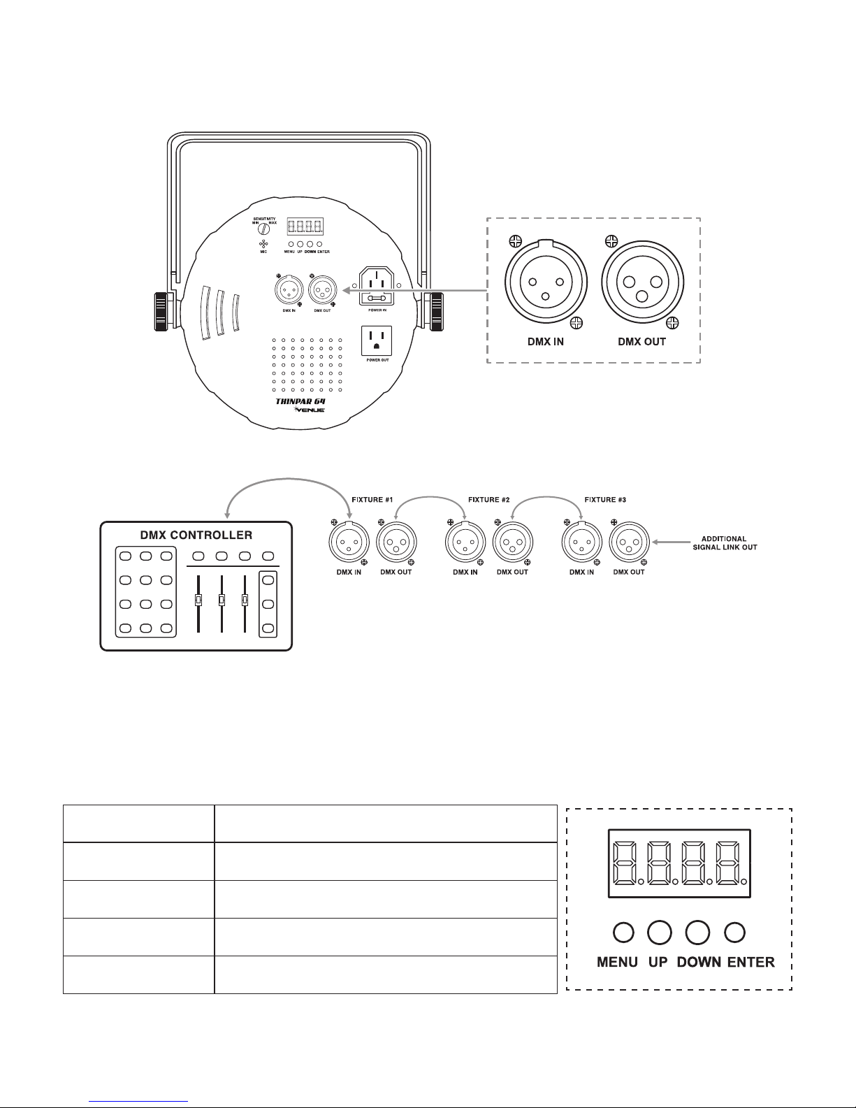
Back Panel ..............................................................5
4. SETUP ....................................................................6
AC power.................................................................6
Power linking ...........................................................6
Mounting orientation................................................7
Rigging ....................................................................7
Signal linking ...........................................................8
5. OPERATING INSTRUCTIONS...............................8
Control panel functions............................................8
Menu map ...............................................................9
6. STANDALONE OPERATION ...............................10
Automatic...............................................................10
Sound-active..........................................................10
Preset colors .........................................................10
Custom static colors ..............................................10
7. DMX OPERATION ................................................11
Configuring the starting address ...........................11
Master/slave (standalone operating modes) .........11
7-Ch mode DMX operation....................................12
3-Ch mode DMX operation....................................12
8. APPENDIX............................................................13
DMX primer ...........................................................13
General troubleshooting ........................................13
Fixture linking ........................................................14
DMX data cable.....................................................14
Cable connectors...................................................14
3-Pin to 5-pin conversion chart..............................15
Setting up a DMX serial data link ..........................15
General maintenance ............................................15
9. TECHNICAL SPECIFICATIONS ..........................16
10. WARRANTY .........................................................16
INTRODUCTION
The Venue Thinpar 64 is a DMX intelligent LED Par Can. It is lightweight and compact which makes it a great light for
Houses of Worship, mobile DJs, clubs and parties. This unit can be used as a stand alone fixture in sound-activated
mode, or controlled via DMX controller.

www.venuelightingeffects.com 3
1. BEFORE YOU BEGIN
WHAT IS INCLUDED
• Thinpar64 • PowerCord
• WarrantyCard • UserManual
UNPACKING INSTRUCTIONS
Carefullyunpackthecarton,thencheckthecontentstoensurethatallpartsarepresentandhavebeenreceivedingood
condition.Notifytheshipperimmediatelyandretainpackingmaterialforinspectionifanypartsappeardamagedfrom
shipping, or the carton itself shows signs of mishandling. Save the carton and all packing materials. In the event that a
xturemustbereturnedtothefactory,itisimportantthatthexturebereturnedintheoriginalfactoryboxandpacking.
MANUAL CONVENTIONS
Venue®manualsusethefollowingconventionstodifferentiatecertaintypesofinformationfromtheregulartext.
CONVENTION MEANING
<Menu> Keytobepressedonthexture’sControlDisplay
1~512 Range of values
50/60 Setofvaluesofwhichonlyonecanbechosen
Settings Menu option not to be modified (for example, showing the operating mode/
current status)
MENU > Settings Sequence of menu options to be followed
ON Value to be entered or selected
ICONS
This manual uses the following icons to indicate information that requires special attention on the part of the user.
ICONS MEANING
This paragraph contains critical installation, configuration or operation
information.Failuretocomplywiththisinformationmayrenderthexture
partiallyorcompletelyinoperative,causedamagetothextureorcause
harm to the user.
This paragraph contains important installation or configuration information.
Failuretocomplywiththisinformationmaypreventthexturefrom
functioningcorrectly.
Thisparagraphremindsyouofuseful,althoughnotcritical,information.

THINPAR 64 USERS MANUAL
4
2. SAFETY INSTRUCTIONS
Pleasereadtheseinstructionscarefully.Itincludesimportantinformation
about the installation, usage and maintenance of this product.
• PleasekeepthisUserManualforfuturereference.
• Makesurethatyouareconnectingtothepropervoltage,andthatthelinevoltageyouareconnectingto
is not higher than that stated on the decal or rear panel of the fixture.
• Thisproductisintendedforindooruseonly!Topreventriskofreorshock,donotexposexturetorain
or moisture.
• Makesuretherearenoammablematerialsclosetotheunitwhileoperating.
• Theunitmustbeinstalledinalocationwithadequateventilation,atleast20”(50cm)fromadjacent
surfaces. Be sure that no ventilation slots are blocked.
• Alwaysdisconnectfromthepowersourcebeforeservicingorreplacingthefuseandbesuretoreplace
withsametypefuse.
• Securexturetofasteningdeviceusingasafetychain.
• Maximumambienttemperatureis104°F(40°C).Donotoperatethextureattemperatureshigher
than this.
• Intheeventofaseriousoperatingproblem,stopusingtheunitimmediately.Nevertrytorepairthe
unityourself.
• Neverconnectthedevicetoadimmerpack.
• Makesurethepowercordisnevercrimpedordamaged.
• Neverdisconnectthepowercordbypullingortuggingonthecord.
• Nevercarrythexturedirectlyfromthecord.Alwaysusethehanging/mountingbracket.
• Avoiddirecteyeexposuretothelightsourcewhileitison.

www.venuelightingeffects.com 5
3. INTRODUCTION
CONTROL FEATURES
• StaticcolorsandRGBcolormixingwithorwithoutDMXcontroller
• Built-inautomatedprogramsviamaster/slaveorDMXwithvariablespeed
• Built-insoundactivatedprogramsviamaster/slaveorDMX
• Pulseeffectwithadjustablespeed
• 3or7channelDMX-512operation
ADDITIONAL FEATURES
• 2.5”lowproledesign
• Powerlinking:40units@120V,60units@230V,10Acircuitmax
• Double-bracketyokedoublesasoorstand
BACK PANEL
AUDIO
SENSITIVITY
ADJUSTMENT
(see pg 10)
MICROPHONE
(see pg 10)
POWER
LINKING
(see pg 6)
CONTROL
DISPLAY
(see pg 8)
DMX
CONNECTION
JACKS
(see pg 8)

THINPAR 64 USERS MANUAL
6
4. SETUP
AC POWER
This fixture runs on 100~240 VAC, 50/60 Hz. Before powering on the unit, make sure the line voltage is within the
range of accepted voltages.
To determine the power requirements for a particular fixture, see the label affixed to the back plate of the fixture
orrefertothexture’sspecicationschart.Axture’slistedcurrentratingindicatesitsaveragecurrentdrawunder
normal conditions.
Alwaysconnectthexturetoaswitchedcircuit.Neverconnectthexturetoarheostat(variableresistor)or
dimmercircuit,eveniftherheostatordimmerchannelisusedonlyasa0to100%switch.
Alwaysconnectthexturetoacircuitwithasuitableelectricalground.
POWER LINKING
This fixture contains power linking via the outlet located on the back panel. Please see the diagram below for
further explanation.
Themaximumquantityofxturesthatmaybelinkedis40units@120V,60units@230V,10Acircuitmax.

www.venuelightingeffects.com 7
MOUNTING ORIENTATION
ThelightweightThinPar64maybemountedinanyposition.
RIGGING
Besurethatthestructurecansupporttheweightofthexture.Pleaseseethe“TechnicalSpecications”sectionofthis
manualforadetailedweightlisting.Mountthexturesecurely.Thismaybedonewithascrew,nutandbolt,orahanging
clamp (not included).The hole in each bracket can fit a 13mm screw or bolt.When rigging, consider routine maintenance
and back panel access. Please see the following steps for installation.
• Ifthepowerlinkoutisintendedtobeusedwithmultiplextures,takeintoaccountthelengthofeachpower
cable, and mount the fixtures close enough to one another to account for this.
• Whenaimingthextures,youmayusethebracketangleknob.Loosentheknob,adjusttothedesiredangle,
andthentightentheknobbyturningclockwise.Donotusetoolsforthisstep,asitmaycausedamage.
• Thereisasecondarybracket,whichmaybeusedprimarilyforoorstandingpositions.
• Safetycablesmustalwaysbeused.
BRACKET ANGLE KNOB
Note: Do not use a tool on
the bracket angle knob.
Tighten or loosen by hand.
MOUNTING BRACKET
SECONDARY BRACKET
(use primarily for floor standing position)

THINPAR 64 USERS MANUAL
8
SIGNAL LINKING
InordertousethisxtureinaDMXormaster/slaveoperation,youmustdaisychainusingDMXcablestolinkfrom
one fixture to another.
5. OPERATING INSTRUCTIONS
CONTROL PANEL BUTTONS
AccessthesefunctionsusingthefourbuttonslocateddirectlyunderneaththeLEDControlDisplay.
BUTTON FUNCTION
<MENU> Scrolls through the current operating mode, as well as back out of
the current menu option
<UP> Selects increasing advancement in the value
<DOWN> Selects decreasing advancement in the value
<ENTER> Selectsavalueandstoreittomemory
AUDIO
SENSITIVITY
ADJUSTMENT
(see pg 10)
MICROPHONE
(see pg 10)
POWER
LINKING
(see pg 6)
CONTROL
DISPLAY
(see pg 8)
DMX
CONNECTION
JACKS
(see pg 8)

www.venuelightingeffects.com 9
The Control Display shows the current state of the unit. It is used to select the operating mode, as well as the
sub-features. For detailed functions, please see the section below.
CONTROL PANEL MENU SELECTIONS
MAIN FUNCTION SUB-FUNCTION SELECTION SUB-SELECTION INSTRUCTION
AUTO P--
P1 7 Color Switching
Select between 2
switching and 2 fading
built-in programs.
P2 7 Color Fading
P3 3 Color Switching
P4 3 Color Fading
SOUND
ACTIVE P-- P5 7 Color Sound Active Use the Audio Sensi-
tivityAdjustmentknob
located on the back
of the fixture.
Select between
2 sound active
programs.
P6 3 Color Sound Active
DMX
CONTROL
3-CH d 1-d512 Select 3-channel DMX
mode (RGB control).
7-CH d 1-d512
COLOR
PALLETTE C--
C1 Red
Select between
7 static colors.
Thedisplaywill
read C1~C7. The
colors that each of
these represent are
indicated to the left.
C2 Green
C3 Blue
C4 Cyan
C5 Magenta
C6 Yellow
C7 White
PRESET SPEED
(1-4) S-- 5 1-5100 (the default range is
5050)
This is the speed
range for the 4
switching and fading
built-in programs.
USER COLOR
MIXING U--
r--- Red
000-100
Combine red, green,
and blue to create a
custom, static color.
g--- Green
b--- Blue

THINPAR 64 USERS MANUAL
10
6. STANDALONE OPERATION
AUTOMATIC
Thisxturehaspreprogrammedchases.TheseareaccessedviatheControlDisplay(page5).Thespeedmaybe
adjustedforthechases.
1. Press <MENU> until “P--”appearsontheLEDscreen.
2. Press <ENTER>.
3. Using <UP> and <DOWN>, select the desired program (P1-P4).
4. Press <ENTER>.
5. Press <MENU> until “S--”appearsontheLEDscreen.
6. Using <UP> and <DOWN>, select the desired program speed (S 1-S100).
7. Press <ENTER> to confirm settings.
SOUND-ACTIVE
Thisxturehaspreprogrammedsoundtriggeredchases.TheseareaccessedviatheControlDisplay(page5).The
audiosensitivitymaybeadjustedusingtheAudioSensitivityAdjustmentknob.
1. Press <MENU> until “P--”appearsontheLEDscreen.
2. Press <ENTER>.
3. Using <UP> and <DOWN>, select the desired program (P5-P6).
4. Press <ENTER> to confirm settings.
PRESET COLORS
Thisxturehaspreprogrammedstaticcolorpresets.TheseareaccessedviatheControlDisplay(page5).
1. Press <MENU> until “C--”appearsontheLEDscreen.
2. Press <ENTER>.
3. Using <UP> and <DOWN>, select the desired color preset (C1-C7).
4. Press <ENTER> to confirm settings.
CUSTOM STATIC COLORS
Thisxturehastheabilitytoacceptcustomstaticcolorsettings.TheseareaccessedviatheControlDisplay(page5).
1. Press <MENU> until “U--”appearsontheLEDscreen.
2. Press <ENTER>.
3. Using <UP> and <DOWN>, select the desired color (r, g, b).
4. Press <ENTER>.
5. Using <UP> and <DOWN>, select the desired color value (000-100).Byselecting000, the color will remain off.
6. Press <ENTER> to continue to the next color (r, g, b).
7. Using <UP> and <DOWN>, select the desired color value (000-100).Byselecting000, the color will remain off.
8. Repeat steps 6 & 7 until the desired color is obtained. Press <ENTER> to save the final color setting. This will move
theselectiontothefollowingcolor;however,thisisnecessarytosavethemodication.
Thecolorsarerepresentedbythefollowinginthemenumap:
r = Red (000-100)
G = Green (000-100)
b = Blue (000-100)

www.venuelightingeffects.com 11
7. Dmx OPERATION
This is the operating mode which will allow for an external DMX controller. You must set the starting address for this
mode.IfthisisyourrsttimeusingDMX,thenitisrecommendedthatyourefertothe“DMXPrimer”sectioninthe
“Appendix”ofthismanual.
1. Press <MENU> until “3-CH”or“7-CH”appearsontheLEDscreen.
2. Press <ENTER>.
3. Using <UP> and <DOWN>, select the desired DMX address (d 1-d512).
CONFIGURING THE STARTING ADDRESS
Each fixture requires a starting address from 1~512. A fixture requiring one or more channels for control begins to
readthedataonthechannelindicatedbythestartingaddress.Forexample,axturethatusessevenDMXchannels
andisaddressedtostartonDMXchannel100,willreaddatafromchannels:100,101,102,103,104,105and106.
Choosethestartingaddressesforeachxturesothatthechannelsuseddonotoverlap.Inaddition,youshouldnote
the starting address selected for future reference.
TheThinpar64usessevenorthreeDMXchannels.IfthisisyourrsttimeusingDMX,werecommendreadingthe
“DMXPrimer”sectioninthe“Appendix”.
MASTER/SLAVE (STANDALONE OPERATING MODES)
This is the operating mode which will allow one fixture to act as the master and control all of the other slave fixtures.
You must set both the master and the slave(s) fixtures to the correct mode for this operation.
Master Settings:
1.ConnectthextureswithDMXcables,asshowninthe“FixtureLinking”section.
2.Useanyoneofthestandalonemodesforthemasterunit.Thisincludes:“P--”,“C--”,and“U--”.
Slave Settings:
1. Press <MENU> until “3-CH” or “7-CH” appears on the LED screen.
2. Press <ENTER>.
3. Using <UP> and <DOWN>, set the DMX address to “d 1”.
4. Press <ENTER>.
AlthoughanyxtureintheDMXdaisychainmaybesettomaster,itisadvisabletosetthemasterastherst
fixture in the line.
Onlyonexturemaybesettomaster.
DonotconnectaDMXcontrollertothedaisychainforthisoperatingmode.
It does not matter which DMX mode is selected for the slave fixtures. Either mode will be effective.

THINPAR 64 USERS MANUAL
12
7-CH MODE DMX OPERATION
CHANNEL VALUE FUNCTION
1000 - 255 Red
Dimmer:0%-100%
2000 - 255 Green
Dimmer:0%-100%
3000 - 255 Blue
Dimmer:0%-100%
4000 - 015
016 - 255
Color Macros (override CH.1 - 3)
No Function
Color Macros
5
000 - 255 Speed(CH.6@values32-223)
Slow - Fast
000 - 015
016 - 255
Strobe(RGBmodeonly)
No Function
Slow - Fast
6
000 - 031
032 - 063
064 - 095
096 - 127
128 - 159
160 - 191
192 - 223
224 - 255
Mode
RGB mode
Pulseeffect0%~100%(usingRGBfaders)
Pulseeffect100%~0%(usingRGBfaders)
Pulseeffect100%~0%~100%(usingRGBfaders)
Auto fade transition
Auto snap transition (3 colors)
Auto snap transition (7 colors)
Sound triggering mode
When CH.6 is set between
032~223, CH.5 controls the
speed.
7000 - 255 Dimmer
Intensity:0%-100%(RGB/Macromodes)
3-CH MODE DMX OPERATION
CHANNEL MEANING FUNCTION
1 000 - 255 Red
Dimmer:0%-100%
2 000 - 255 Green
Dimmer:0%-100%
3 000 - 255 Blue
Dimmer:0%-100%

www.venuelightingeffects.com 13
8. APPENDIx
DMX PRIMER
Thereare512channelsinaDMXconnection.Channelsmaybeassignedinanymanner.Axturecapableofreceiving
DMX will require one or a number of sequential channels. The user must assign a starting address on the fixture that
indicatestherstchannelreservedinthecontroller.TherearemanydifferenttypesofDMXcontrollablexturesand
theyallmayvaryinthetotalnumberofchannelsrequired.Choosingastartaddressshouldbeplannedinadvance.
Channelsshouldneveroverlap.Iftheydo,thiswillresultinerraticoperationofthextureswhosestartingaddressisset
incorrectly.Youcanhowever,controlmultiplexturesofthesametypeusingthesamestartingaddressaslongasthe
intended result is that of unison movement or operation. In other words, the fixtures will be slaved together and will all
respondexactlythesame.ConsulttheOwner’sManualtoyourDMXcontrollerformoreinformation.
DMXxturesaredesignedtoreceivedatathroughaserialDaisyChain.ADaisyChainconnectioniswheretheDATA
OUT of one fixture connects to the DATA IN of the next fixture. The order in which the fixtures are connected is not
important and has no effect on how a controller communicates to each fixture. Use an order that provides for the easiest
and most direct cabling. Connect fixtures using shielded two-conductor twisted pair cable with three pin XLR male to
female connectors. The shield connection is pin 1, while pin 2 is Data Negative (S-), and pin 3 is Data Positive (S+).
GENERAL TROUBLESHOOTING
SYMPTOM POSSIBLE CAUSE(S) POSSIBLE ACTION(S)
Breaker/Fuse keeps blowing •Excessivecircuitload
•Shortcircuitalongthepowerwires
•Checktotalloadplacedontheelectricalcircuit.
•Checkforashortintheelectricalwiring(internaland/
or external).
Device does not power up •Nopower
•Loosepowercord
•CheckforpoweronMains.
•Checkpowercord
Fixture is not responding to DMX
•WrongDMXaddressing
•DamagedDMXcables
•Wrongpolaritysettingsonthecontroller
•LooseDMXcables
•FaultyDMXinterface
•FaultyMainPCB
•CheckControlDisplayandunitaddressing
•CheckDMXcables
•Checkpolarityswitchsettingsonthecontroller
•Checkcableconnections
•ReplaceDMXinput
•ReplaceMainPCB
Loss of signal
•NonDMXcables
•Bouncingsignals
•Longcable/Lowlevelsignal
•Toomanyxtures
•InterferencefromACwires
•UseonlyDMXcompatiblecables
•Installterminatorassuggested
•Installamplierrightafterxturewithstrongsignal
•InstallanopticallycoupledDMXsplitterafterunit#32
•KeepDMXcablesseparatedfrompowercablesor
black light

THINPAR 64 USERS MANUAL
14
FIXTURE LINKING
YouwillneedaserialdatalinktorunlightshowsofoneormorexturesusingaDMXcontrollerortorunsynchronized
showsontwoormorexturessettoamaster/slaveoperatingmode.Thecombinednumberofchannelsrequiredbyall
the fixtures on a serial data link determines the number of fixtures the data link can support.
Fixturesonaserialdatalinkmustbedaisychainedinonesingleline.TocomplywiththeEIA-485standard,no
more than 32 fixtures should be connected on one data link. Connecting more than 32 fixtures on one serial data
linkwithouttheuseofaDMXoptically-isolatedsplittermayresultindeteriorationoftheDMXsignal.
Maximumrecommendedserialdatalinkdistance: 500m(1640ft)
Maximumrecommendednumberofxturesonaserialdatalink: 32
DMX DATA CABLE
Use a cable which meets the specifications for EIA RS-485 applications. Standard microphone cables cannot transmit
DMXdatareliablyoverlongdistances.Thecablemusthavethefollowingcharacteristics:
Type: shielded,2-conductor,twistedpair
Maximumcapacitancebetweenconductors: 30pF/ft
Maximumcapacitancebetweenconductorandshield: 55pF/ft
Maximumresistance: 20Ohms/1000ft
Nominalimpedance: 100~140Ohms
CABLE CONNECTORS
Cabling must have a male XLR connector on one end and a female XLR connector on the other end.
Donotallowcontactbetweenthecommonandthexture’schassisground.Groundingthecommoncan
causeagroundloop,andyourxturemayperformerratically.TestcableswithanOhmmetertoverifycorrect
polarityandtomakesurethepinsarenotgroundedorshortedtotheshieldoreachother.

www.venuelightingeffects.com 15
3-PIN TO 5-PIN CONVERSION CHART
Ifyouuseacontrollerwitha5-pinDMXoutputconnector,youwillneedtousea5-pinto3-pinadapter.The
chartbelowdetailsapropercableconversion:
3-PIN TO 5-PIN CONVERSION CHART
Conductor 3-Pin Female (Output) 5-Pin Male (Input)
Ground/Shield Pin 1 Pin 1
Data ( - ) signal Pin 2 Pin 2
Data ( + ) signal Pin 3 Pin 3
Not used Pin 4
Not used Pin 5
SETTING UP A DMX SERIAL DATA LINK
1. Connect the (male) 3-pin connector side of the DMX cable to the output (female) 3-pin connector of the controller.
2. Connect the end of the cable coming from the controller which will have a (female) 3-pin connector to the input
connector of the next fixture consisting of a (male) 3-pin connector.
3. Then, proceed to connect from the output as stated above to the input of the following fixture and so on.
GENERAL MAINTENANCE
Tomaintainoptimumperformanceandminimizewear,xturesshouldbecleanedfrequently.Usageandenvironment
arecontributingfactorsindeterminingfrequency.Asageneralrule,xturesshouldbecleanedatleasttwiceamonth.
Dust reduces performance and can cause overheating. This can lead to reduced lamp life and increased mechanical
wear. Be sure to power off fixture before conducting maintenance.
• Unplugxturefrompower.
• Useavacuumoraircompressorandasoftbrushtoremovedustcollectedonexternalvents.
• CleanallglasswhenthextureiscoldwithamildsolutionofglasscleanerorIsopropylAlcoholandasoft
lint-free cotton cloth or lens tissue.
• Applysolutiontotheclothortissueanddragdirtandgrimetotheoutsideofthelens.
• Gentlypolishopticalsurfacesuntiltheyarefreeofhazeandlint.
Thecleaningofexternalopticallensesand/ormirrorsmustbecarriedoutperiodicallytooptimizelightoutput.Cleaning
frequencydependsontheenvironmentinwhichthextureoperates.Damp,smokyorparticularlydirtysurroundingscan
causegreateraccumulationofdirtontheunit’soptics.Cleanwithsoftclothusingnormalglasscleaninguid.Cleanthe
externalopticsatleastevery20days.Cleanthextureatleastevery30/60days.
Alwaysdrypartscarefullyaftercleaningthem.
Never spin a fan using compressed air.

THINPAR 64 USERS MANUAL
16
9. TECHNICAL SPECIFICATIONS
Weight & Dimensions
Length................................................................................................................................9.7”(246mm)
Width ................................................................................................................................11.1”(282mm)
Height ...................................................................................................................................2.5”(63mm)
Weight.............................................................................................................................. 2.8 lbs (1.3 kg)
Power
Auto-rangingpowersupply ................................................................................100~240 VAC, 50/60 Hz
PowerConsumption@120V...........................................................................18 W max, 0.25 A inrush
PowerConsumption@230V...........................................................................16 W max, 0.14 A inrush
Power output........................................................... 40units@120V,60units@230V,10Acircuitmax
Fuse..................................................................................................................................... F 1 A, 250 V
Light Source
LEDs.......................................................................................................180 (60 red, 60 green, 60 blue)
Photo Optic
Lux@1m ...................................................................................................................................... 3,640
Beam angle ........................................................................................................................................23°
Field angle ..........................................................................................................................................38°
Thermal
Maximum ambient temperature........................................................................................ 104°F(40°C)
10. WARRANTY
One(1)YearLimitedWarranty
Subjecttothelimitationssetforthbelow,Venue®herebyrepresentsandwarrantsthatthecomponentsofthisproduct
shallbefreefromdefectsinworkmanshipandmaterials,includingimpliedwarrantiesofmerchantabilityortnessfora
particularpurpose,subjecttonormaluseandservice,forone(1)year(ninety(90)daysonlamps)totheoriginalowner
from the date of purchase.
Retailer and manufacturer shall not be liable for damages based upon inconvenience, loss of use of product, loss of
time,interruptedoperationorcommerciallossoranyotherincidentalorconsequentialdamagesincludingbutnotlimited
tolostprots,downtime,goodwill,damagetoorreplacementofequipmentandproperty,andanycostsofrecovering,
reprogramming,orreproducinganyprogramordatastoredinequipmentthatisusedwithVenue®products. This guar-
anteegivesyouspeciclegalrights.Youmayhaveotherlegalrightswhichvaryfromstatetostate.Somestates
donotallowlimitationsonhowlonganimpliedwarrantylasts,sotheabovelimitationmaynotapplytoyou.
Venue Lighting Effects
P.O. Box 5111, Thousand Oaks, CA 91359-5111
www.venuelightingeffects.com
Alltrademarksandregisteredtrademarksmentionedhereinarerecognizedasthepropertyoftheirrespectiveholders.
Made in China. 1106-9592
This manual suits for next models
1
Table of contents
Other Venue Floodlight manuals
Popular Floodlight manuals by other brands

UltraLux
UltraLux SPX22090 user manual

i-WATTS
i-WATTS I-SPB10W-700SMD Original instructions

Chauvet
Chauvet Nexus Aq 5x5 Quick reference guide

Ledino
Ledino 11150106001111 instruction manual

luceco
luceco Guardian Slimline LFSP10W1B30 Installation & operating instructions

Eaton
Eaton Crouse-hinds series Installation & maintenance information

Perel
Perel LEDA200 NW-BP Series user manual

Flash butrym
Flash butrym PAR64 quick start guide

Color imagination
Color imagination LEDBEAM 120F SI-029 user manual

Berner
Berner COB LED NG-Floodlight 40W-Accu instruction manual

Equinox Systems
Equinox Systems Triclops Beam user manual

Chauvet
Chauvet COLORband T3 USB user manual