Verdant VX Series User manual

VXDB-TW-KT-W
VX Series Wireless Thermostat with
an Occupancy Sensor
INSTALLATION MANUAL
JUNE 2020

3
Table of Contents
Introduction.............................................................................................................5
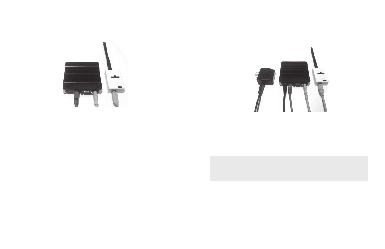
Network Installation.................................................................................................7
Connecting the Antenna Module.............................................................................. 7
Connecting the Ethernet Cable ................................................................................ 8
Powering the Server ................................................................................................. 9
Conguring the Online Connection Kit................................................................... 10
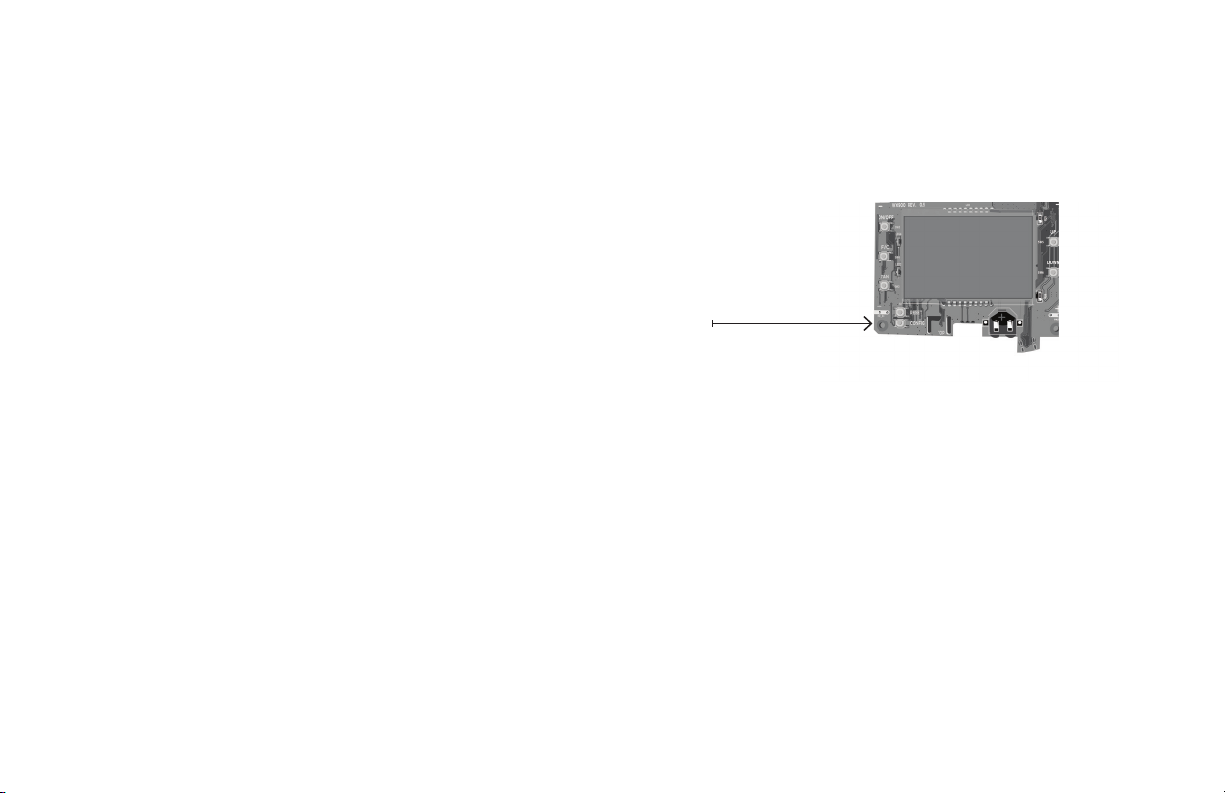
HVAC Controller Installation...................................................................................11
Thermostat Installation ..........................................................................................13
Thermostat Conguration......................................................................................14
Accessing the Conguration Screen .......................................................................15
Pairing an HVAC Controller to a Wireless Thermostat ............................................. 16
Setting the MESH ID............................................................................................... 17
Entering the Room Number....................................................................................18
Conguring the Equipment Settings....................................................................... 19
Conguring the Energy Saving Settings .................................................................20
Setting the Thermostat Clock ................................................................................21
Testing the Thermostat.......................................................................................... 22
Thermostat Maintenance .......................................................................................23
Accessory Conguration (Optional)........................................................................24
Accessing the Sensor Setup Menu ..........................................................................24
Activating a Sensor................................................................................................. 25
Discovering a Sensor .............................................................................................. 26
Congure the Functionality of a Sensor ..................................................................26
Pairing a Sensor with the HVAC Controller.............................................................. 27
Completing the Sensor Setup ................................................................................ 28
Troubleshooting.....................................................................................................29
Error Codes ............................................................................................................ 29
Restoring Factory Settings ..................................................................................... 30
BLANK
PAGE

4 5
Table of Contents Introduction
Verdant VX Series Energy Management Thermostats deliver unprecedented energy
savings without compromising the comfort of occupants.
An Integrated occupancy sensor uses a combination of motion and thermal sensing
technologies for accurate occupancy detection. Reliable occupancy detection allows
for energy savings when rooms are unoccupied.
Energy saving presets eliminate the guesswork and make it easy to adjust the energy
saving settings.
Fully congurable energy saving settings allow for customization of the thermostat
energy saving settings to t any situation.
Comprehensive conguration options ensure full compatibility with virtually any
existing or emerging HVAC system with up to 2 heat and 1 cool stages.
Built-in wireless mesh-networking enables online management.
APPENDIX 1 - Energy Saving Presets .......................................................................31
APPENDIX 2 - Glossary............................................................................................32
Warranty Information.............................................................................................33
Technical Specications.......................................................................................... 34

6 7
NOTICE
TO ENABLE NETWORKING CAPABILITIES OF THE VX THERMOSTAT, REFER
TO THE “NETWORK INSTALLATION” SECTION OF THIS MANUAL.
BEFORE STARTING THE INSTALLATION OF THE NETWORKED THERMOSTATS,
ENSURE THAT THE ONLINE CONNECTION KIT IS CONNECTED TO THE
INTERNET.
THE ONLINE CONNECTION KIT MUST BE PLUGGED INTO AN INTERNET
PORT WITH A PRIVATE IP ADDRESS WITH DHCP ACTIVE. THE ONLINE
CONNECTION KIT MUST BE WHITELISTED USINGS ITS MAC ADDRESS WITH
UNRESTRICTED INTERNET ACCESS. PORTS 80,443, AND 22 MUST BE OPEN
TO INBOUND/OUTBOUND COMMUNICATION.
PLEASE CONFIRM WITH A VERDANT TECHNICAL SUPPORT AGENT THAT
THE ONLINE CONNECTION KIT IS COMMUNICATING PROPERLY WITH THE
CLOUD SERVICE BY CALLING OUR TECHNICAL SUPPORT TEAM AT 1 877 318
1823.
Network Installation
Connecting the Antenna Module
➤Screw the Antenna onto the Wireless Receiver;
➤Connect the Wireless Receiver to the Server using the supplied USB cable;
➤Afx the Wireless Receiver to the wall with double sided adhesive tape;
➤Orient the antenna to be parallel to the closest room in which a Verdant
thermostat will be installed.
THE WIRELESS RECEIVER AND THE ANTENNA MUST NOT BE INSTALLED NEAR
METAL STRUCTURES OR SURFACES.
METAL STRUCTURES AND SURFACES SIGNIFICANTLY REDUCE THE RANGE OF THE
WIRELESS SIGNAL.

8 9
Online Connection Kit Installation
Connecting the Ethernet Cable
➤Connect the Server to the LAN port with the supplied RJ-45 cable.
Online Connection Kit Installation
Powering on the Server
➤Plug the Server into an electrical outlet with the supplied power cord.
TO PREVENT POWER RELATED ISSUES, PLUG THE SERVER INTO A UPS
(UNINTERRUPTED POWER SUPPLY) UNIT.

10 11
Online Connection Kit Installation
Conguring the Online Connection Kit
➤Ensure the Online Connection Kit is receiving a Private or Static IP address via
DHCP Server. A public IP will not work;
➤Ensure that the MAC address is properly Whitelisted if it needs to bypass
a login (splash) page to be able to reach the internet. The MAC address is
printed on a white sticker on the bottom of the Online Connection Kit.
➤If behind a rewall, ports 22,80, and 443 must be open for the Online
Connection Kit.
HVAC Controller Installation
Installing the HVAC Controller in an HVAC Unit
➤Power Off the HVAC unit;
➤Connect the HVAC Controller to the thermostat terminals on the HVAC unit -
refer to the Wiring Table to determine proper connections.
THE HVAC CONTROLLER ANTENNA MUST BE FACING THE THERMOSTAT AND
MUST NOT BE TOUCHING OR ENCLOSED BY ANY METAL COMPONENTS IN THE
HVAC UNIT.
THE HVAC CONTROLLER MUST BE MOUNTED SO IT CANNOT FALL INTO THE HVAC
UNIT CONDENSATION PAN. WE RECOMMEND USING PLASTIC CABLE TIES, OR 3M
COMMAND TAPE (NOT SUPPLIED).
Terminal
Letter
Terminal
Connection AC Only AC + HEAT HP Only HP + HEAT
WHeat X✔X✔
YCompressor ✔ ✔ ✔ ✔
O/B Reverse Valve X X ✔ ✔
C Common ✔ ✔ ✔ ✔
R 24V ✔ ✔ ✔ ✔
GL Fan Low ✔ ✔ ✔ ✔
GH Fan High ✔ ✔ ✔ ✔
Aux Aux Optional
NOTE: If the HVAC unit has only one (1) fan speed, connect both fan control
wires – Green and Purple – to the fan terminal (G).

12 13
HVAC Controller Installation
IF THE HVAC UNIT VOLTAGE OUTPUT IS MORE THAN 30VAC, YOU WILL REQUIRE A
HIGH VOLTAGE HVAC CONTROLLER (VX-HV-CC).*
PLEASE VERIFY THAT YOU HAVE THE CORRECT PARTS BEFORE BEGINNING
INSTALLATION. IF YOU DO NOT HAVE THE CORRECT PARTS, CEASE INSTALLATION
IMMEDIATELY AND CALL VERDANT TECHNICAL SUPPORT AT 1 877 318 1823.
Thermostat Installation
THE THERMOSTAT’S OCCUPANCY SENSOR SHOULD FACE THE BED AREA OF
THE ROOM OR THE AREA WHERE THE OCCUPANT WILL SPEND THE MOST
TIME.
THE THERMOSTAT MUST NOT BE INSTALLED IN THE VICINITY OF METAL
STRUCTURES OR SURFACES INCLUDING METAL AIR DUCTING THAT MAY BE
IN THE WALL.
METAL STRUCTURES AND SURFACES SIGNIFICANTLY REDUCE THE RANGE
OF THE WIRELESS SIGNAL.
DO NOT OVER TIGHTEN THE BACK PLATE TO THE WALL. FOR UNEVEN
SURFACES, CONSIDER INSTALLING A WALL PLATE.
Mounting the Thermostat to the Wall
➤Select the appropriate installation location for the thermostat, taking into
account the following;
➤With the faceplate removed, place the thermostat on the wall in the
installation location and mark location for drilling holes for the two (2)
mounting screws;
➤Drill two (2) 3/16” holes in the wall and insert the two (2) supplied wall
anchors;
➤Use the two (2) supplied screws to securely mount the thermostat to the wall;
➤Insert two (2) AA-cell batteries (not supplied) into the thermostat battery
compartment.
For Installation on PTAC Units;
➤Mount the HVAC Controller inside of the HVAC unit.
➤Set the unit to “External Thermostat” (Class 2) mode. Consult the HVAC
unit documentation to determine how to set the PTAC unit to “External
Thermostat” mode.
For other units;
➤Consult the HVAC manufacturer’s documentation or use a voltmeter to
determine the voltage output (24V).
For Fan Coils;
➤Ensure the HVAC controller is installed outside of the fan coil’s metal
enclosure. The HVAC controller will not communicate properly inside of any
metal enclosure.
➤Ensure to adhere to all applicable electrical codes.

CONFIGURATION BUTTON
NOTE: You can access Thermostat
Confi guration settings at any time by
pressing the “Confi guration” button.
14 15
Thermostat Con gurationThermostat Con guration
Con guring the Thermostat
With the thermostat and HVAC unit powered, follow the con guration instructions
to correctly con gure the thermostat.
To ensure proper operation of the HVAC unit, complete the following steps.
➤Pair the thermostat with the wireless controller
➤Set the MESH ID;
➤Enter the room number;
➤Enter the equipment code;
➤Con gure the energy saving settings;
➤Set the thermostat clock
Accessing the Con guration Screen
➤Ensure the thermostat is powered and faceplate removed;
➤Press the con g button;
The thermostat con guration screens have a 30-second time-out. If no action is
taken within (30) seconds, the thermostat will exit con guration settings.
NOTE: When the thermostat is connected to a network, the equipment and
the energy saving settings con gured on the thermostat will be overidden by
settings con gured online.

16 17
Thermostat Con guration
Pairing the Thermostat and HVAC Controller
The thermostat and HVAC Controller must be paired during installation. The
thermostat will search for the closest HVAC Controller to it and display the unique
HVAC Controller ID. The HVAC Controller ID is located on the case.
➤Verify that the HVAC controller found by the thermostat matches the HVAC
controller listed on the HVAC controller in the same room;
➤Press the F|C button to pair the thermostat with the HVAC Controller
displayed on the screen. The screen will display “SUCC” when the HVAC
Controller has been paired successfully. If the HVAC Controller ID displayed on
the screen is incorrect, press the FAN button to reject it;
➤Press the F|C button to advance to the next con guration menu.
THE WIRELESS CONTROLLER MUST BE LINKED TO A THERMOSTAT IN THE
SAME ROOM. ONLY INSTALL ONE ROOM AT A TIME.
Thermostat Con guration
Setting the MESH ID
➤Press the FAN button to advance to the next digit;
➤Press the UP and DOWN buttons to increase or decrease the value;
➤Press the F|C button to advance to the next menu.

18 19
Thermostat Con guration
Entering the Room Number
Enter the room number by changing the characters on the screen.
Available characters include digits 0-9 and letters A-F. To distinguish between two or
more thermostats in the same unit, enter as follows:
Thermostat 1: 00100
Thermostat 2: 0100A
➤Press the FAN button to advance to the next digit;
➤Press the UP and DOWN buttons to increase or decrease the value;
➤Press the F|C button to advance to the next menu.
Entering the room number correctly is crucial for proper operation of thermostats
with online management.
Thermostat Con guration
Con guring the Equipment Settings
Enter the equipment code by changing the digits on the screen. Refer to the table
below.
➤Press the FAN button to advance to the next equipment setting.
➤Press the UP and DOWN buttons to increase or decrease the value;
➤Press the F|C button to advance to the next menu.
*Indicates default setting.
Digit Setting #1
Compressor Type
Setting #2
Electric Heat
Setting #3
Reversing Valve
Setting #4
Fan Speed
0 No Compressor No Electric Heat O/B Contact is energized
to cool* N/A
1 Heat Pump Electic Heat* O/B Contact is energized
to heat One Fan Speed*
2 Air Conditioner* N/A N/A Two Fan Speeds
3 N/A Three Fan
Speeds

HOURS MINUTES
20 21
Thermostat Con guration
Con guring the Energy Saving Settings
➤Press the UP and DOWN buttons to increase or decrease the energy savings
preset.
➤Press the F|C button to advance to the next menu.
*Indicates default setting.
Preset Energy Savings Presets
E-0* Energy Savings Off - No Temperature Setback
E-1 Lowest Energy Savings
E-2 Lower Energy Savings
E-3 Standard Energy Savings
E-4 Higher Energy Savings
E-5 Highest Energy Savings
Thermostat Con guration
Setting the thermostat clock
Set the thermostat clock to current time in 24h (Military Time) format.
➤Press the FAN button to advance to the next digit;
➤Press the UP and DOWN buttons to increase or decrease the digits
➤Press the F|C button to advance to the next menu.
Setting the clock correctly is crucial for proper operation of the thermostat.

Thermostat Conguration
22 23
Replacing Thermostat Batteries
The low battery indicator will be displayed on the thermostat screen when it is necessary
to replace batteries in the thermostat.
Under normal operating conditions, new brand-name alkaline batteries will last for a
period of approximately eighteen (18) months.
Please replace batteries every sixteen (16) months to ensure continuous thermostat
operation.
To replace thermostat betteries:
➤Remove the thermostat cover;
➤Replace the two (2) AA-cell batteries (not supplied);
➤Re-afx the thermostat cover;
➤Press the ON/OFF button to start using the thermostat.
NOTE: The thermostat maintains all the “Thermostat Conguration” settings in
non-volatile memory. There is no need to congure the thermostat again after
battery replacement.
Thermostat Maintenance
Testing the Thermostat
Following the thermostat conguration, test if the thermostat is controlling the HVAC
unit.
➤Ensure the thermostat is powered and the faceplate is on.
➤Press the DOWN button to change the temperature set point below the
current room temperature to conrm that the thermostat initiates air
conditioning;
➤Press the UP button to change the temperature set point above the current
room temperature to conrm that the thermostat initiates heating;
➤Change the fan speed by touching the FAN button to test if the thermostat is
controlling the fan speed.

Con guring & Managing Accessories
Accessing the Sensor Setup Menu
With the thermostat and HVAC unit powered, follow the sensor con guration
instructions to correctly con gure the sensors.
➤Remove the faceplate from the thermostat
➤Press and hold the con g button until SENS appears on the screen.
CONFIGURATION BUTTON
24 25
Con guring & Managing Accessories
Activating a Sensor
➤Remove the cover of the sensor(s) to be paired in the room;
➤Insert one (1) AAA-cell battery into each sensor (not supplied);
➤Press the button inside the sensor to make the sensor discoverable;*
➤Press the FAN button to initiate the pairing procedure. This may take up to 30
seconds.
*The sensor(s) will remain discoverable for ve (5) minutes after pressing the button
inside the device. If the pairing process has not been completed within ve (5)
minutes of making sensor(s) discoverable, repeat this step.

26 27
Con guring & Managing Accessories
Discovering an Active Sensor
The thermostat will display the rst sensor discovered in the pairing process. Ensure
that the unique device number displayed on the screen matches the unique ID found
on the sensor.
➤Press the F|C button to pair the discovered sensor to the HVAC Controller.
➤Repeat this process as necessary for additional sensors.
If the sensor displayed on the screen is not the correct sensor to pair with the HVAC
Controller, use the UP or DOWN buttons to nd other discovered sensors. To start
over, press the ON/OFF button to exit and refer back to page 24.
Con guring & Managing Accessories
Con gure the Functionality of a Sensor
The thermostat allows the user to change the default functionality of the sensor. Use
the table below to con gure the desired functionality.
➤Press the FAN button to advance to the next digit;
➤Press the UP and DOWN buttons to increase or decrease the digit;
➤Hold the F|C to save sensor settings.
*Indicates default setting.
Functionality Sensor Functionality Code
Occupancy Sensor 100
Sensor with Magnetic
door switch 010*
Temperature Sensor 001

28 29
Con guring & Managing Accessories
Completing the Sensor Setup
The thermostat will countdown from thirty (30) seconds. If the sensor has
successfully paired, the thermostat will display “SUCC”. If the sensor did not pair
successfully, the display will read “FAIL”, and the process must be repeated.
➤Press the ON/OFF button to exit the sensor setup screen.
Error Codes
ERR 1 Thermostat Temperature Sensor Hardware Defect
ERR 2 Thermostat Radio Hardware Defect
ERR 3 Thermostat Radio Software Defect
ERR 4 No link with the HVAC Controller
ERR 5 Thermostat Memory Defect
Troubleshooting

30 31
Restoring Factory Settings
If there are reported errors or conguration issues, the user may restore factory
settings to return the thermostat to its default parameters.
Procedure
➤Power down the thermostat by either removing the batteries or cutting power
to the thermostat;
➤Remove the faceplate of the thermostat;
➤Press and hold the CONFIG button located on the control board inside the
thermostat while simultaneously powering the thermostat;
➤Release the CONFIG button once the thermostat powers up;
➤If the master reset was successful, the thermostat will display 12:00 and the
thermostat must be re-congured. Please refer to pages 14-22 of this manual.
Contact Verdant technical support if the issues are not resolved.
Troubleshooting Guide APPENDIX 1 - Energy Saving Presets
Level
0
Level
1
Level
2
Level
3
Level
4
Level
5
Fan Control Mode AUTO AUTO AUTO AUTO AUTO AUTO
1st Stage Differential Heat 0.5 0.5 0.5 0.5 0.5 0.5
2nd Stage Differential Heat 111222
1st Stage Differential Cool 0.5 0.5 0.5 0.5 0.5 0.5
Guest Occupancy Threshold
055555
Night Occupancy Threshold 111111
Force 2nd Stage Heating After 30 30 30 30 30 30
Night Occupancy Start 18 19 20 21 22 23
Night Occupancy End 12 11 10 9 8 7
Recovery Time 015 20 25 30 0
Recovery Temperature Heat 70 69 68 67 66 65
Setback Delay - Heat 030 25 20 15 10
Minimum Setback Temperature 67 66 65 64 63 62
Setback Delay - Cool 030 25 20 15 10
Maximum Setback Temperature 72 74 76 78 80 82
Recovery Temperature Cool 71 72 73 74 75 76
Minimum Set point 64 64 65 66 67 68
Maximum Set point 82 82 80 78 76 74
Temperature Control Mode AUTO AUTO AUTO AUTO AUTO AUTO
Auto Changeover Set Point Offset
Dead Band) 111111
Auto Restore OFF ON ON ON ON ON
Setback Set Points OFF ON ON ON ON ON
Automatic Humidity Control ON ON ON ON ON ON
Temperature Calibration 000000

32 33
“Automatic Fan Control Mode” - fan runs only when there
is a demand for heating or cooling;
“Manual Fan Control Mode” - guest can select between
automatic or continuous fan operation;
“Minimum Set point” - minimum temperature that a
guest can request;
“Maximum Set point” - maximum temperature that a
guest can request;
“Auto Changeover Set Point Offset” - the difference
between the guest-selected set point and the heat and
cool changeover temperatures;
“1st Stage Differential - Heat” - the temperature that
the thermostat has to sense between the automatic
changeover temperature for heat and the room
temperature before a call for the 1st stage heating is
initiated;
“2nd Stage Differential - Heat” - difference between 1st
stage heating temperature and room temperature before
the 2nd stage heating is initiated;
“1st Stage Differential - Cool” - the temperature that
the thermostat has to sense between the automatic
changeover temperature for cool and the room
temperature before a call for the 1st stage cooling is
initiated;
“Forced 2nd Stage Heating” - number of minutes 1st
stage heating will run before 2nd stage heating is
automatically initiated if the guest set point is not reached
and the 2nd stage heating is not initiated through
differential settings
“Temperature Recovery Time” - the maximum period of
time allowed for restoring the “Recovery Temperature”;
“Recovery Temperature” - the room temperature that
needs to be restored within the “Temperature Recovery
Time”;
“Maximum Setback Temperature” - the highest room
temperature allowed when thermostat is in the setback
mode;
“Minimum Setback Temperature” - the lowest room
temperature allowed when thermostat is in the setback
mode;
“Temperature Setback Delay” - the length of time for
which the room that is in the guest occupancy mode
needs to be unoccupied before the temperature setback
is initiated;
“Incidental Occupancy Threshold” - the minimum period
of time (in minutes) for which occupancy needs to be
detected in order to enter the “Guest Occupancy” mode;
“Night Occupancy Threshold” - the minimum period
of time during the “Night Occupancy” period for which
occupancy needs to be detected in order to enter the
“Night Occupancy” mode;
“Night Occupancy Period” - The period of time during the
day during which the “Night Occupancy” mode can be
activated if occupancy longer than the “Night Occupancy
Threshold” is detected;
“Auto Restore On” - thermostat will restore the most
recent guest settings when new occupancy is detected;
“Auto Restore Off” - thermostat will NOT restore the most
recent guest and will remain turned off settings when new
occupancy is detected;
“Setback Set points On” - thermostat will maintain
setback temperatures when room is unoccupied;
“Setback Set points Off” - thermostat will NOT maintain
setback temperatures when room is unoccupied;
“Incidental Occupancy” - occupancy shorter than the
“Incidental Occupancy Threshold”;
“Guest Occupancy” - occupancy longer than the
“Incidental Occupancy Threshold”;
“Temperature Setback” - thermostat maintains setback
temperatures and not the guest set point temperature in
order to save energy;
“Night Occupancy Mode” - thermostat status during
which setback mode is disabled if occupancy longer than
“Night Occupancy Threshold” is detected within the
“Nigh Occupancy” period;
“Automatic Temperature Changeover” - thermostat
automatically activates heating or cooling to maintain the
desired room temperature;
“External Thermostat” (Class 2) mode - HVAC unit setting
allowing it to be controlled by a remote thermostat;
APPENDIX 2 - Glossary Warranty Information
For the most recent warranty information, please visit www.verdant.co/verdant-warranty.

THIS DEVICE COMPLIES WITH PART 15 OF THE FCC RULES. OPERATION IS SUBJECT
TO THE FOLLOWING TWO CONDITIONS: (1) THIS DEVICE MAY NOT CAUSE HARMFUL
INTERFERENCE, AND (2) THIS DEVICE MUST ACCEPT ANY INTERFERENCE RECEIVED,
INCLUDING INTERFERENCE THAT MAY CAUSE UNDESIRED OPERATION.
THE MANUFACTURER IS NOT RESPONSIBLE FOR ANY RADIO OR TV INTERFERENCE CAUSED BY
UNAUTHORIZED MODIFICATIONS TO THIS EQUIPMENT. SUCH MODIFICATIONS COULD VOID THE
USER’S AUTHORITY TO OPERATE THE EQUIPMENT
This device complies with Industry Canada license-exempt RSS standard(s). Operation is subject to
the following two conditions: (1) this device may not cause interference, and (2) this device must
accept any interference, including interference that may cause undesired operation of the device.
Le présent appareil est conforme aux CNR d’Industrie Canada applicables aux appareils radio
exempts de licence. L’exploitation est autorisée aux deux conditions suivantes : (1) l’appareil ne
doit pas produire de brouillage, et (2) l’utilisateur de l’appareil doit accepter tout brouillage radio
électrique subi, même si le brouillageest susceptible d’en compromettre le fonctionnement.
Under Industry Canada regulations, this radio transmitter may only operate using an antenna of
a type and maximum (or lesser) gain approved for the transmitter by Industry Canada. To reduce
potential radio interference to other users, the antenna type and its gain should be so chosen that
the equivalent isotropically radiated power (e.i.r.p.) is not more than that necessary for successful
communication.
Conformément à la réglementation d’Industrie Canada, le présent émetteur radio peut fonctionner
avec une antenne d’un type et d’un gain maximal (ou inférieur) approuvé pour l’émetteur par
Industrie Canada. Dans le but de réduire les risques de brouillage radioélectrique à l’intention
des autres utilisateurs, il faut choisir le type d’antenne et son gain de sorte que la puissance
isotroperayonnéequivalente (p.i.r.e.) ne dépassepasl’intensiténécessaire à l’établissementd’une
communication satisfaisante.
BLANK
PAGE

36
Technical Specications
Thermostat HVAC Controller
Case Dimensions (Imperial) 4.015 x 5.5118” x 0.925” 4.84” x 2.76” x 1.02”
Case Dimensions (Metric) 102mm x 140mm x 23.5mm 123mm x 70mm x 26mm
Screen Dimensions (Imperial) 3.625" x 2.125" N/A
Screen Dimensions (Metric) 92mm x 54mm N/A
Operating Voltage
3V DC - 2 "AA" Cell Batteries
24V
Control Outputs Fan High (GH)
Fan Low (GL)
Compressor (Y)
Heat Pump (OB)
Electric Heat (W2)
Occupancy Out (AUX)
Occupancy Sensor Beam Width
±47° (94°) N/A
Wireless Frequency 900MHz 900MHz
Temperature Accuracy ±1°F N/A
FCC ID XEYWX-DB XEY-ZX-LV
IC 8410A-WXDB 8410A-ZXLV
COVERED BY ONE OR MORE OF THE FOLLOWING PATENTS. US PATENTS: 8,369,994; 8,141,791; 7,918,406; 7,232,075;
7,185,825; 7,156,318; 7,152,806; 7,145,110; 7,050,026; 7,028,912; 6,902,117; 6,789,739; 6,786,421; 6,619,555;
6,581,846; 6,578,770; 7,838,803; 7,841,542; D556,061; D518,744; RE40,437; CANADIAN PATENTS: 2,633,113;
2,633,200; OTHER PATENTS PENDING.
Verdant Environmental Technologies, Inc. reserves the right to make changes, without notice, in design or components.
Product appearance may vary.
© Verdant Environmental Technologies, Inc. 2020.
Printed in Canada. V.1 JUNE 2020
Other manuals for VX Series
3
This manual suits for next models
1
Table of contents
Other Verdant Thermostat manuals

Verdant
Verdant VX-TW User manual

Verdant
Verdant V8-BB-7S User manual

Verdant
Verdant VX-TW Installation and maintenance instructions

Verdant
Verdant VX Series User manual

Verdant
Verdant VX Series Operating and maintenance instructions

Verdant
Verdant VX-TR Installation and maintenance instructions

Verdant
Verdant VX Series User manual

Verdant
Verdant Wireless User manual