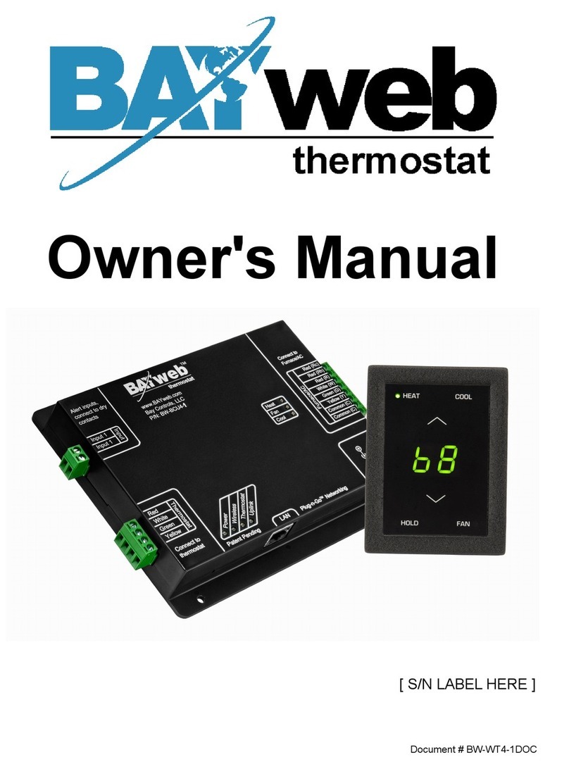
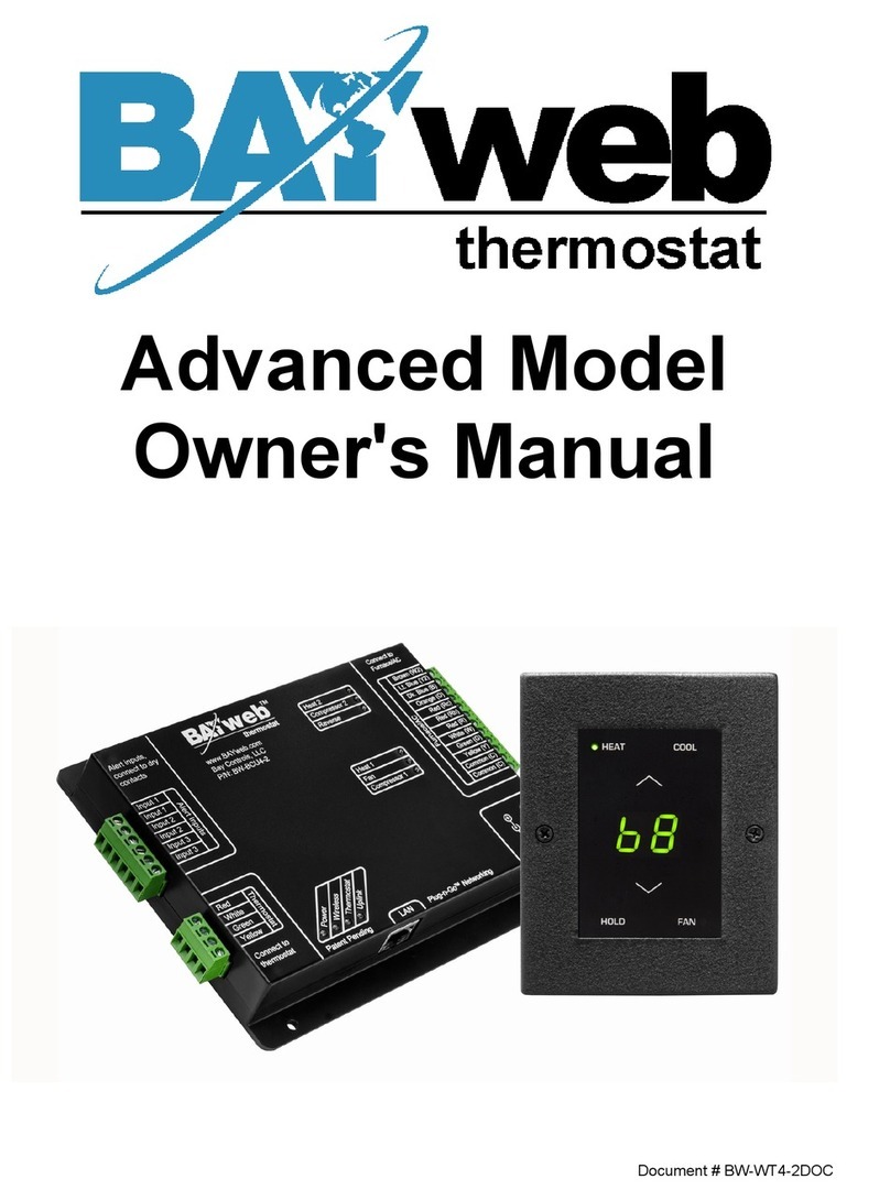
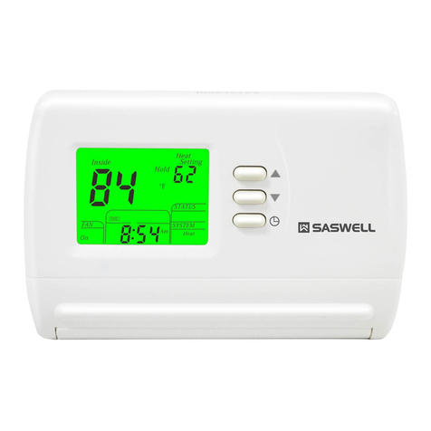
BAYweb BW-WT8 User manual

Professional Model
Owner's Manual
Document # BW-WT8DOC

BAYweb Thermostat Model BW-WT8 Owner's Manual
Copyr ght © 2009-2011 Bay Controls, LLC
Rev s on: 1.8 October 13, 2011
BAYweb s a reg stered trademark of Bay Controls, LLC.
Patent pend ng technolog es are used n the BAYweb Thermostat.

Table of Contents
Introduct on.............................................................................................................1
About Th s Manual..................................................................................................1
Safety Precaut ons..............................................................................................1
L m ted Warranty.................................................................................................3
L m tat on on L ab l ty..........................................................................................3
Unauthor zed Repa r...........................................................................................3
Installat on...............................................................................................................4
Overv ew.............................................................................................................4
Ident fy W r ng.....................................................................................................6
Install Control Module.........................................................................................8
Install Thermostat Keypad................................................................................10
Connect to the Internet.....................................................................................11
Conf gure the Thermostat.................................................................................12
Test Operat on..................................................................................................13
Operat on..............................................................................................................14
Us ng the Thermostat Keypad..........................................................................14
Us ng the Web S te...........................................................................................14
Us ng Your Mob le Phone.................................................................................15
Occupancy Sens ng..........................................................................................15
Implement ng Occupancy Sens ng...............................................................15
Test ng Occupancy Sens ng.........................................................................16
Occupancy Sens ng w th Mult ple Thermostats...........................................16
Alert ng..............................................................................................................17
Implement ng Alert ng...................................................................................17
Test ng Alert ng.............................................................................................17
Reference..............................................................................................................18
Thermostat Keypad..........................................................................................18
Error Codes..................................................................................................18
Control Module.................................................................................................19
Alert Inputs...................................................................................................19
Thermostat Connector..................................................................................20
Furnace/AC Connector.................................................................................20
LAN Port.......................................................................................................20
Power Supply...............................................................................................20
Status Ind cators...........................................................................................20
Troubleshoot ng................................................................................................21
Solut ons to Problems..................................................................................22
Obta n ng Support........................................................................................26
Opt onal Inputs..................................................................................................26
D g tal............................................................................................................26
Temperature.................................................................................................26
Supply Temperature.....................................................................................26
Outdoor A r Temp..........................................................................................27

Average Control............................................................................................27
Area Control.................................................................................................27
Opt onal Outputs...............................................................................................27
Relay Control................................................................................................27
Hum d f er Control.........................................................................................27
Damper Control............................................................................................27
Thermostat Connect ons..................................................................................28
Thermostat W r ng............................................................................................28
Spec f cat ons........................................................................................................29

Introduction
Thank you for purchas ng the BAYweb Thermostat. You now have one of the most advanced
Heat ng, Vent lat ng, and A r Cond t on ng (HVAC) control systems ava lable today.
Th s thermostat s eas ly nstalled by home owners or HVAC profess onals. It can be used to
replace an ex st ng thermostat or for nstallat on w th new heat ng or cool ng equ pment.
Th s model of the BAYweb Thermostat (BW-WT8) s des gned for use w th convent onal or
heat pump based systems that use s ngle or mult stage stage control.
About This Manual
Th s manual conta ns the nformat on necessary for nstall ng and operat ng the BAYweb
Thermostat. However, s nce nstallat ons may vary, these nstruct ons may not cover all deta ls
or var at ons n the equ pment suppl ed or every quest on that may poss bly ar se dur ng use.
If a quest on or s tuat on develops wh ch s not answered d rectly n th s manual, contact
BAYweb support for spec f c answers and adv ce.
You should become fam l ar w th the contents of th s manual before the thermostat s put nto
serv ce. Th s s part cularly mportant w th regard to the safety precaut ons l sted n the
Introduct on sect on, and those ncluded at relevant po nts n other sect ons of th s manual.
Note that th s manual s s updated per od cally. You can download the latest vers on at
www.bayweb.com.
CAUTION: Read, be sure to clearly understand, and then carefully follow all of the
d rect ons and procedures ncluded n th s manual. Fa lure to adhere to the
gu del nes and spec f c nstruct ons prov ded could cause equ pment damage and
ser ous personal njury or death.
Safety Precautions
Low voltage thermostats, nclud ng the BAYweb Thermostat, use 24 VAC control s gnals
l m ted to 3.2 amperes to nterface to your furnace and a r cond t on ng equ pment. These low
voltage control s gnals do not normally represent an electr c shock hazard unless used n an
env ronment for wh ch the equ pment was not des gned for, such as a wet locat on.
1
!

Bay Controls, LLC. expressly d scla ms respons b l ty or l ab l ty for any njury or damage
caused by fa lure to observe spec f ed or other common safety precaut ons or fa lure to
exerc se ord nary caut on, common sense, and due care requ red n nstall ng and operat ng
the thermostat even though not spec f ed here n.
The alert message shown here appears throughout th s manual to nd cate those s tuat ons
and t mes when spec al care s necessary to prevent equ pment damage or personal njury.
CAUTION: Th s nd cates that there could be the poss b l ty of equ pment damage
or personal njury.
CAUTION: If th s equ pment s used n a manner not spec f ed by Bay Controls,
LLC., there may be a r sk of equ pment damage, ser ous personal njury, or death.
2
!
!

Limited Warranty
Subject to the l m tat ons conta ned below, and except as otherw se expressly prov ded
here n, Seller warrants to the Buyer that all tang ble art cles suppl ed by Seller or serv ces
prov ded by Seller w ll be free of defects n mater als or workmansh p under normal use and
care unt l the exp rat on of the appl cable warranty per od. Goods are warranted for f ve (5)
years from the date of purchase. If Buyer d scovers any defects and not f es Seller thereof n
wr t ng dur ng the appl cable warranty per od, Seller shall at ts opt on promptly correct, repa r,
or replace F.O.B. po nt of manufacture that port on of the good found by Seller to be defect ve,
or refund the purchase pr ce of the defect ve port on of the goods/serv ces. All replacements
or repa rs necess tated by nadequate ma ntenance, normal wear and usage, unsu table
power sources, unsu table env ronmental cond t ons, acc dent, m suse, mproper nstallat on,
mod f cat on, repa r, storage or handl ng, or any other cause not the fault of Seller are not
covered by th s l m ted warranty, and shall be at Buyer’s expense. Seller shall not be obl gated
to pay any costs or charges ncurred by Buyer except as may be agreed upon n wr t ng n
advance by an author zed Seller representat ve. Goods repa red and parts replaced dur ng
the warranty per od shall be n warranty for the rema nder of the or g nal warranty per od or
n nety (90) days, wh chever s longer.
THERE ARE NO REPRESENTATIONS OR WARRANTIES OF ANY KIND, EXPRESS OR
IMPLIED, AS TO MERCHANTABILITY, FITNESS FOR PARTICULAR PURPOSE, OR ANY
OTHER MATTER WITH RESPECT TO ANY GOODS OR SERVICES.
Limitation on Liability
THE SOLE AND EXCLUSIVE REMEDY FOR BREACH OF WARRANTY HEREUNDER
SHALL BE LIMITED TO REPAIR, CORRECTION, REPLACEMENT OR REFUND OF
PURCHASE PRICE AS PROVIDED UNDER THE FOREGOING LIMITED WARRANTY.
IN NO EVENT, REGARDLESS OF THE FORM OF THE CLAIM OR CAUSE OF ACTION
(WHETHER BASED IN CONTRACT, INFRINGEMENT, NEGLIGENCE, STRICT LIABILITY,
TORT OR OTHERWISE), SHALL SELLER’S LIABILITY TO BUYER AND/OR ITS
CUSTOMERS EXCEED THE PRICE TO THE BUYER OF THE SPECIFIC GOODS
SUPPLIED OR SERVICES PROVIDED BY SELLER GIVING RISE TO THE CLAIM OR
CAUSE OF ACTION.
BUYER AGREES THAT IN NO EVENT SHALL SELLER’S LIABILITY TO BUYER AND/OR
ITS CUSTOMERS INCLUDE “CONSEQUENTIAL DAMAGES”. FOR THIS PURPOSE,
“CONSEQUENTIAL DAMAGES” SHALL INCLUDE, BUT NOT BE LIMITED TO, LOSS OF
ANTICIPATED PROFITS, LOSS OF USE, LOSS OF REVENUE AND LOSS OF CAPITAL.
Unauthorized Repair
In the event that the owner allows the Web Thermostat to be serv ced or repa red by
unauthor zed personnel, the coverage of the or g nal warranty pol cy w ll be automat cally
term nated.
3

Installation
Overview
Install ng the thermostat s a relat vely s mple process and typ cally takes from 10 to 30
m nutes to complete. You should cons der the current outdoor temperature. If unexpected
problems occur, you do not want to r sk freez ng or overheat ng wh le you are sort ng out the
problem.
You w ll need screwdr vers, a w re str pper/cutter, and a dr ll for nstall ng the wall anchors to
complete the nstallat on. A volt/ohm meter can be helpful for troubleshoot ng but s not
requ red.
Most convent onal thermostats, probably nclud ng the one you are replac ng, use a s ngle
wall mounted enclosure. The BAYweb thermostat uses two modules: the Thermostat Keypad
and the Control Module. Th s des gn el m nates the use of batter es and potent al need to pull
new w re out to the wall, and results n a more compact and elegant des gn.
The Thermostat Keypad s mounted on wall n place of
your ex st ng thermostat.
If your ex st ng thermostat s larger than the new one,
you can eas ly pull off the keypad later to touch up the
pa nt after you have completed the nstallat on.
The control module mounts near or on your
furnace and/or a r cond t oner, and s spl ced
nto your ex st ng thermostat w re.
The module can be powered d rectly from the
furnace or from an outlet deally on the same
c rcu t as your furnace.
You w ll need an Internet connect on for the
Control Module.
If t s not conven ent to plug nto your network
there, cons der us ng an opt onal power-l ne
Ethernet adapter.
4

Your ex st ng nstallat on s should be
s m lar to th s dep ct on.
You have a s ngle thermostat cable
go ng between your wall mounted
thermostat and the furnace.
The cable conta ns from 2 to 5 w res of
d fferent colors.
Your BAYweb Thermostat nstallat on s shown below. The Control Module s mounted near
the furnace or a r cond t oner and s w red nto the ex st ng thermostat cable. The control
module s powered from a standard outlet.
The spec f c nstallat on steps to replace your ex st ng thermostat w th the new BAYweb
Thermostat are shown n the rema nder of the nstallat on nstruct ons. If you are nstall ng the
thermostat w th new equ pment, the process w ll be s m lar except for removal of the old
equ pment.
CAUTION: Be sure to rev ew all of the nstallat on steps before start ng your
nstallat on.
5
Thermostat Cable
!
Thermostat Cable
Thermostat Cable

1Identify Wiring
The object ve of th s step s to dent fy how your thermostat w r ng s connected to your
furnace, a r cond t oner, or heat pump. Th s w ll also determ ne what type of control
scheme your system uses.
A) Turn off all power to your furnace, a r cond t oner, or heat pump.
CAUTION: Ver fy that all power has been turned off. Fa lure to turn power
off may result n personal njury, electr c shock, and equ pment damage.
B) Go to your ex st ng thermostat and remove the cover or remove t from the wall as
needed so you can see the term nals where the w r ng s attached.
C) Note what connect ons your system uses and ver fy that your thermostat s us ng the
correct term nals w th the correct w re color as shown n the table below.
If your nstallat on s us ng non standard w re colors, you w ll have to note what color s
be ng used for what term nal and match your w re colors to the appropr ate term nal.
Terminal unction Standard
Wire Color
My Wire
Color
Connected
(Y/N) ?
R 24 VAC supply for heat/cool Red
Rh 24 VAC supply for heat Red
Rc 24 VAC supply for cool Red
W or W1 or
Aux
Heat or Aux Heat Wh te
G Fan Green
Y or Y1 Cool Yellow
W2 2nd Stage Heat Brown
Y2 2nd Stage Cool L ght Blue
O Revers ng Valve Orange
B Revers ng Valve Dark Blue
E Emergency Heat Var es
C or X 24 VAC Common Blue or Black
6
!

D) If you do not have a w re attached to term nal “C” or “X”, you w ll need to use the
ncluded power supply to power the thermostat. The power supply plugs nto a
standard 120VAC outlet and to a connector on the control module.
E) The follow ng table shows what term nals are used by the d fferent control methods.
Determ ne wh ch control method your system s us ng by match ng wh ch term nals are
connected to your w r ng.
C rcle the number of the system type that you have. You w ll use th s nformat on when
conf gur ng your thermostat n Step 5.
If you have a w re connected to term nal “E”, you have a heat pump w th an emergency
heat funct on. If you do not also have a w re connected to term nal “W” you w ll need to
connect the w re connected to “E” to term nal “W”.
# System Type
Terminals
W or W1 or Aux Y W2 Y2 O or B
1 Convent onal Heat Only* Y
2 Convent onal Cool Only* Y
3 Convent onal One Heat/One Cool Y Y
4 Convent onal Two Heat/One Cool Y Y Y
5 Convent onal Two Heat/Two Cool Y Y Y Y
6 Convent onal One Heat/Two Cool Y Y Y
7 Heat Pump One Heat/One Cool Y Y
8 Heat Pump Two Heat/One Cool Y Y ** Y
9 Heat Pump Two Heat/Two Cool Y Y Y
10 Heat Pump Three Heat/Two Cool Y Y ** Y Y
If you have any quest on on what system type you have, contact support
([email protected]) or contact your local HVAC serv ce company.
* NOTE: The BAYweb Thermostat requ res at least 4 w res n the thermostat cable
between the Thermostat keypad and the Control Module. If you have a heat or cool
only system that only has 2 w res, you w ll need to nstall new thermostat w re. It s less
des rable, but often poss ble to obta n sat sfactory operat on us ng 3 w res. Consult the
Frequently Asked Quest ons sect on at www.bayweb.com for more nformat on.
** NOTE: Some heat pump nstallat ons may use a wh te w re on W2 nstead of W1 for
aux l ary heat. If you have a wh te w re attached to term nal W2 of your thermostat t
should be connect to the W1 term nal of the BAYweb Thermostat.
7

2Install ontrol Module
A) F nd your thermostat cable where t goes nto the furnace, a r cond t oner, or heat
pump. Th s s the same cable dent f ed n Step 1 and should be the same color and
th ckness as that cable.
CAUTION: There may be other cables of s m lar color connect ng other
dev ces such as a hum d f er. Be sure to use the cable that runs back to your
thermostat and not one that s connected to another dev ce. Connect ng the
Web Thermostat to the wrong cable can result n electr c shock and/or
equ pment damage.
B) Mount the Control Module us ng the follow ng cr ter a:
◦Select a locat on near the furnace where there s suff c ent room to mount the
Control Module along where the thermostat cable runs. The thermostat cable w ll
need to reach both the “Thermostat” and “Furnace/AC” term nals of the Control
Module.
◦If you w ll be us ng the ncluded power supply (see Step 1D), select a locat on w th n
4 feet of a power outlet, deally on the same c rcu t as the furnace/AC.
◦Select a locat on where you can connect to the Internet. If w r ng s not conven ent,
we suggest us ng a power l ne Ethernet adapter that w ll allow you to make th s
connect on us ng your ex st ng power w r ng.
C) Prepare the thermostat cable:
W th the furnace, a r cond t oner, or heat pump power OFF, cut the thermostat w re at a
po nt where both ends w ll be able to reach the Control Module mount ng locat on.
Us ng a w re-str pp ng tool, str p approx mately 2 nches of the outer jacket off both
ends of the thermostat cable, then str p approx mately ¼ nch off the end of each of the
thermostat w res.
D) Connect the w r ng go ng to the Thermostat Keypad:
Attach the w res n the cable com ng from the thermostat to the term nals on the LE T
s de of the control module nto the connector labeled "Thermostat". Be sure to match
the w re color and term nal des gnat on as dent f ed n Step 1. If you have more w res
than the four w res labeled on the connector (Red, Wh te, Green, Yellow), bend them
back out of the way and tape to the cable. They w ll not be used.
Note that you need four w res between the Control Module and Thermostat Keypad
even f you have a heat or cool only system.
8
!

E) Connect the w r ng go ng to the furnace, a r cond t oner, or heat pump:
Attach the w res n the cable com ng from the furnace to the term nals on the RIGHT
s de of the control module labeled " urnace/AC". Be sure to match the w re color and
term nal des gnat on as dent f ed n Step 1.
NOTE: If your system uses separate Rh and Rc w res, be sure to remove the jumper
w re between the Rh and Rc term nals. If your system uses a s ngle Red w re, make
sure the jumper w re between term nals Rh and Rc s nstalled.
CAUTION: It s very mportant to connect the thermostat cable to the correct
connectors on the Control Module. If you connect the control module
“Thermostat” connector to your furnace or air conditioner wiring, the
control module will be damaged.
F) Conf rm that the term nal screws are t ght, the w res w ll not pull out of the term nals,
and that there are not any shorts between term nals.
9
!

3Install Thermostat Keypad
A) Remove the w res from your ex st ng thermostat, tak ng care that the w res do not fall
back nto the wall.
B) Remove the ex st ng thermostat and any assoc ated mount ng hardware.
C) F ll n any holes from the prev ous thermostat mount ng and pa nt the wall f needed.
D) Hold the Thermostat Keypad n the des red pos t on and mark the locat on of the
mount ng screws. Dr ll 3/16 nch holes and nstall the suppl ed wall anchors. Note that f
your thermostat was nstalled us ng an electr cal box, the keypad w ll mount d rectly to
a standard electr cal box us ng the suppl ed screws.
E) Make sure the ends of each w re are str pped and ready to be attached to the new
Thermostat Keypad. If any w res break off then use your w re str pper to str p
approx mately ¼ nch of nsulat on from the end of the w re.
F) Us ng the suppl ed w re nuts, attach the four colored w res com ng from the Thermostat
Keypad (red, wh te, green, yellow) to the four match ng colored w res from the cable n
the wall. If your nstallat on uses non standard w re colors, use the table you completed
n step 1C to connect your w re colors to the standard color of the Thermostat Keypad.
G) If you have any spare w res not be ng used, cut off any bare sect ons and ensure that
they w ll not short to anyth ng n the Thermostat Keypad.
H) Push the thermostat cable nto the wall to remove as much slack as poss ble. F t any
excess w r ng nto the space beh nd the Thermostat Keypad.
I) Attach the Thermostat Keypad to the wall us ng the suppl ed screws.
10

4onnect to the Internet
The BAYweb Thermostat s factory conf gured for system type 3, convent onal one
heat/one cool. Th s w ll also work for system types 1 and 2. If you have a mult stage
furnace, a r cond t oner, or heat pump, you w ll need to connect the thermostat to the
Internet and conf gure t for the type of system that you have pr or to use.
A) Connect the Control Module to the Internet. Plug one end of an Ethernet cable nto the
LAN port on the bottom of the Control Module and the other end nto a port on a router
or sw tch on your local network.
B) If d rect w r ng s not conven ent, use Power L ne Ethernet adapters. Plug one adapter
nto a power plug near the control module and the other adapter near your router. Then
just plug the Ethernet cables nto the adapters and the ports.
C) The BAYweb Thermostat does not requ re any conf gurat on or programm ng of your
network ng equ pment. You do not need to change secur ty sett ngs. Just plug t n and
you are all set to go.
D) Plug n the control module. Do not power up your furnace, a r cond t oner, or heat pump
yet. The Power LED on the control module should llum nate.
E) In less than a m nute the “Upl nk” l ght should llum nate on the control module. If you
do not see “Upl nk” l ght up w th n a couple of m nutes, refer to the Troubleshoot ng
sect on of th s manual.
11

5onfigure the Thermostat
The thermostat s conf gured us ng the BAYweb web s te. The follow ng steps w ll gu de you
through sett ng up your web s te account and conf gur ng the thermostat. If you have already
setup your account, s mply cl ck on the “Dev ces” l nk to add the thermostat.
A) Go to the BAYweb s te by enter ng www.bayweb.com n the address bar of your web
browser.
B) Cl ck on the “Create an account” l nk.
C) Enter the requested nformat on.
D) You w ll be sent an ema l to conf rm you have entered a val d ema l address and
val date your dent ty w th the g ven ema l. You must follow the nstruct ons n the ema l
to act vate your account.
E) Once your account has been act vated, log n to the web s te at www.bayweb.com us ng
your user ID and password.
F) After logg ng n, cl ck on the “Dev ces” l nk.
G) Cl ck the “Add” button on the Dev ces page.
H) Enter the ser al number and key code from the label on the Control Module.
I) When prompted for the “System Type”, enter the type you determ ned n nstallat on
step 1E. Once th s s complete, the thermostat s conf gured for your spec f c
equ pment.
12

6Test Operation
A) Turn the power back on to the furnace, a r cond t oner, or heat pump.
B) Ver fy that the “Power” and “Thermostat” l ghts are llum nated on the control module. If
e ther one s not on, refer to the Troubleshoot ng sect on of th s manual.
C) Ver fy that the Thermostat Keypad s show ng the temperature. If t s show ng an “E”
w th a number, th s s an error code. Refer to the Troubleshoot ng sect on.
D) Test FAN operat on: Press the keypad near the “FAN” label. An LED should llum nate
next to the label and the fan should be runn ng. Press FAN aga n and the fan w ll turn
off. If the fan d d not operate, consult the Troubleshoot ng sect on of th s manual.
E) Test HEAT operat on: Select heat mode by press ng the keypad near the HEAT label,
an LED should llum nate next to the label. Press the up arrow on the keypad to ra se
the set po nt to at least 2 degrees above the current temperature.
Check your furnace or heat pump and conf rm that t s heat ng. Note that your fan w ll
not run unt l your furnace has heated up. Th s may take a few m nutes.
Note that once the heat turns on, t w ll rema n on for a m n mum of 1 m nute and once
t turns off, f w ll rema n off for 1 m nute as well.
If operat ng correctly, go back to the keypad and change the set po nt back to a normal
level. If heat ng d d not funct on, refer to the Troubleshoot ng sect on.
F) Test COOL operat on:
CAUTION: If the outdoor temperature s below 40º F you should not run your
a r cond t oner as that may result n equ pment damage.
Select cool mode by press ng the keypad near the COOL label. An LED should
llum nate next to the label. Press the down arrow on the keypad to lower the set po nt
to at least 2 degrees below the current temperature.
Check your a r cond t oner or heat pump and conf rm that t s runn ng.
G) If operat ng correctly, go back to the keypad and change the set po nt back to a normal
level. If cool ng d d not funct on, refer to the Troubleshoot ng sect on.
13
!

Operation
Using the Thermostat Keypad
The Thermostat Keypad shows the current temperature, set po nt and modes, and allows you
to manually control your furnace and a r cond t oner.
Using the Web Site
The real power of the BAYweb Thermostat s real zed by us ng the BAYweb web s te to
access your thermostat. Th s web s te can be accessed anyt me from anywhere v a web
browser and Internet enabled mob le phone. Unl m ted use of the web s te s ncluded at no
charge.
If you have not already done so, setup your account by go ng to the web s te
www.bayweb.com, reg ster a new account, log n and add a dev ce (your thermostat). You w ll
need the ser al number from the label on the control module.
14
Ind cators show
Ind cators show
wh ch modes are
wh ch modes are
selected
selected
Press once to show
Press once to show
the current set po nt.
the current set po nt.
Press aga n to
Press aga n to
change.
change.
Press to select
Press to select
HEAT mode. If
HEAT mode. If
selected, press
selected, press
aga n to turn OFF.
aga n to turn OFF.
Press to change
Press to change
HOLD mode. If
HOLD mode. If
selected the
selected the
current set po nt
current set po nt
w ll be used
w ll be used
regardless of
regardless of
schedule.
schedule.
Current
Current
Temperature
Temperature
Press to select
Press to select
COOL mode. If
COOL mode. If
selected, press
selected, press
aga n to turn OFF.
aga n to turn OFF.
Press to change
Press to change
the FAN mode
the FAN mode
between AUTO
between AUTO
and ON.
and ON.

Using Your Mobile Phone
Once you have setup your account on the web s te, you can also use most any mob le phone
that has web access to remotely access your thermostat and other web dev ces. To access
the mob le web s te, enter the follow ng address n your mob le phone browser:
www.bayweb.com/mob le.
Occupancy Sensing
The BAYweb Thermostat can use var ous types of sensors (mot on sensors be ng the most
common) wh ch allow the thermostat to “know” when you are home (Occup ed) or when you
are away (Not Occup ed).
Occupancy sensors enable the Web Thermostat to operate as one of the most eff c ent
thermostat ava lable today. Us ng occupancy sensors w ll save you the most amount of
money and s mpl fy sett ng up your thermostat.
Us ng Occupancy Sens ng allows you to only pay for heat ng or a r cond t on ng to your
comfort level when you are there. Imag ne runn ng out to go shopp ng on a weekend and
be ng gone from your house for say 5 hours. Do you always turn your thermostat down when
you go shopp ng? Now your BAYweb Thermostat can do t for you.
Use of Occupancy Sens ng s mpl f es sett ng up your thermostat’s schedule because all you
need to do s determ ne when you generally are asleep and when you generally wake up ( f
you want your house heated before you wake). The rema nder of the t me you can tell the
thermostat to sense f you are there or not.
Wh le “Sensing”, the thermostat w ll automat cally set back the temperature to your “Away”
set po nt after a per od of t me of not sens ng occupancy. L kew se, upon sens ng occupancy,
t w ll sw tch to your “Home” set po nt.
Schedul ng a “Sleep” act v ty d sables Occupancy Sens ng to prevent sw tch ng to the Home
set po nt f you get up n the m ddle of the n ght and happen to pass a sensor.
Implementing Occupancy Sensing
To enable and use occupancy sens ng you need to nstall one or more occupancy sensors
and conf gure the thermostat to use them on the web s te.
The thermostat can use w reless (X10 w reless protocol) or w red occupancy sensors. Bay
sells a low cost w reless occupancy sensor that s ready to use w th the BAYweb Thermostat.
Just put n a couple of batter es and mount t n a locat on that typ cally sees act v ty when you
are home. You can use as many sensors as needed enabl ng the thermostat to mon tor
mult ple locat ons n your home for occupancy.
W red occupancy sensors can use e ther normally open or closed contacts. Mot on sensors
from most alarm systems are compat ble w th the BAYweb thermostat.
15

Occupancy sens ng w th pets n the home s accompl shed by mask ng off the lower part of
the sens ng lens.
You should locate your sensors n h gh-traff c areas of your house so that they w ll be most
l kely to sense when people are present. The sensors from Bay have a 10+ foot range and w ll
sense people as they pass n front of the sensor. We have found that locat ng them at about
chest he ght or h gher works well.
Once you have nstalled your occupancy sensors log n to the web s te to enable them. To
enable occupancy sens ng select the “Schedule” page from the thermostat menu and set the
“Occupancy Inact v ty T me”. We suggest us ng 1 hour for th s nterval n t ally. You can adjust
th s value later f needed to su t your l festyle.
If you are us ng sensors not suppl ed by Bay, you may need to conf gure the thermostat to
look for other w reless IDs or to mon tor the w red nput. Th s s done on the “Sett ngs” page.
After enabl ng occupancy sens ng rev ew your schedule and set your “Sens ng”, “Sleep” , and
“Home” t mes as descr bed above. Your thermostat w ll now automat cally adapt your HVAC
operat on to match your l festyle.
Testing Occupancy Sensing
If you want to see f the sensors are work ng as expected, log n to the web s te and select
“Sensor Log” from the thermostat menu.
The thermostat “Operat on Log” w ll g ve a deta led v ew of occupancy sens ng operat on.
Occupancy Sensing with Multiple Thermostats
If you are us ng mult ple BAYweb thermostats n the same bu ld ng, and w sh to have each
thermostat sense occupancy (us ng w reless sensors) n separate areas, you w ll need to
conf gure the occupancy sensors w th d fferent X10 dev ce IDs.
The default X10 ID of Bay suppl ed sensors s “A1”. Note that these sensors also use an ID
that s one more than what s conf gured (default “A2”) for other purposes, do not use the next
ID for occupancy sens ng. For example, acceptable IDs would be A1, A3, A5...
Refer to the nstruct ons prov ded w th the sensor for deta l on how to change the sensor's
X10 ID. Conf gure the thermostat to look for the alternate X10 IDs on the “Sett ngs” page.
16
Table of contents
Other BAYweb Thermostat manuals
