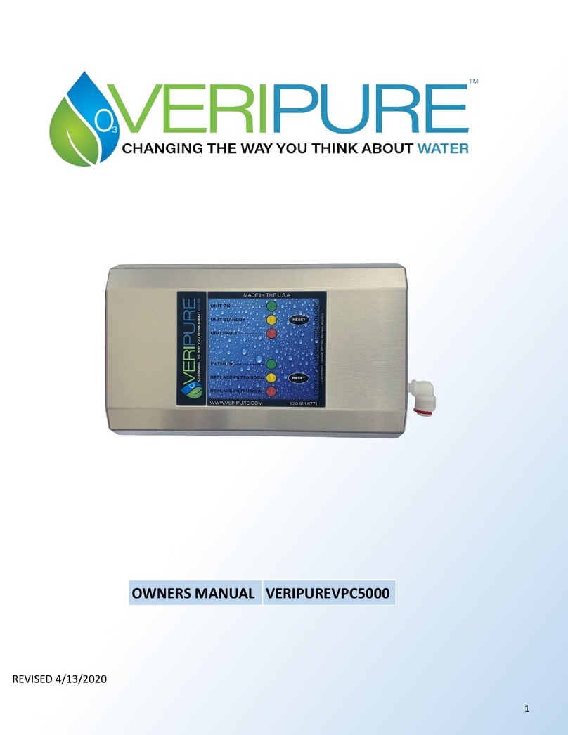
VERIPURE VERIPUREVP5000 User manual

1
REVISED 4/13/2020
OWNERS MANUAL VERIPUREVP5000

2
2425 HUTSON ROAD
GREEN BAY WI, 54303
(920) 613-6771
www.veripure.com
THANK YOU FOR CHOOSING VERIPURE®
PLEASE TAKE A FEW MOMENTS TO FILL IN THE INFORMATION BELOW, SAVE THIS
MANUAL AS A CONVENIENT INFORMATION SOURCE FOR YOUR VERIPURE® SYSTEM.
Date of Purchase:
Purchased From:
Phone Number:
Serial Number:
Installed By:
Dealer Name:
Dealer Phone

3
PERFORMANCE DATA SHEET
Model VPC5000 & Model VP5000
This system has been tested by WQA according to NSF/ANSI 42 and 53 for the reducon of the substances
listed below. The concentraon of the indicated substances in water entering the system was reduced to a
concentraon less than of equal to the permissible limit for water leaving the system, as specied in NSF/
ANSI 42 and 53. While tesng was performed under standard laboratory condions, actual performance
may vary. Do not use with water that is microbiologically unsafe or of unknown quality without adequate
disinfecon before or aer the system. Systems cered for cyst reducon may be used on disinfected
waters that may contain lterable cysts.
Stage One — Filtraon Process:
The VeriPure Maintenance Kit- Consists of a two lter conguraon that is a proprietary design of VeriPure, Inc. The rst lter
is a sediment lter that greatly reduces suspended and parculate maer from the incoming water source. The second lter
(a carbon block lter for cyst removal, lead and chlorine reducon) greatly reduces free chlorine and cysts from the water
source to disinfect and improve the taste and odor of the water.
Carbon Block Filter Data
Operang Specicaons:
Capacity: 1 ,250 Gallons Lead Reducon
Flow Rate: 0.50 to 1.0 GPM
Minimum Pressure: 50 PSI
Maximum Pressure: 125 PSI
Temperature: 35-90 F (2-32 C)
Parameter
Chlorine >=50%
Cyst >=99.95%
Lead 0.01 mg/L

4
IMPORTANT SAFEGUARDS AND PRECAUTIONS
INSTALL YOUR VERIPURE® SYSTEM IN COMPLIANCE WITH STATE AND LOCAL LAWS AND REGU-
LATIONS FOR PLUMBING AND ELECTRICAL CODES. AS WITH ANY WATER DEVICE, PLEASE
CHECK YOUR SYSTEM FOR LEAKS ON A REGULAR BASIS. CONTACT A PLUMBER IMMEDIATELY
VERIPURE® PERFORMANCE IS BASED UPON INPUT WATER WHICH MEETS MINIMUM EPA NA-
TIONAL PRIMARY AND SECONDARY DRINKING WATER STANDARDS.
SEE WWW.EPA.GOV/DWSTANDARDSREGULATIONS
ATTENTION: THIS UNIT IS DESIGNED FOR TREATMENT OF COLD WATER ONLY.
READ INSTRUCTIONS- ALL SAFETY AND OPERATING INSTRUCTIONS SHOULD BE READ BEFORE THE UNIT IS OPERATED.
RETAIN INSTRUCTIONS– SAFETY AND OPERATING INSTRUCTIONS SHOULD BE KEPT IN AN ACCESSIBLE LOCATION
FOR FUTURE REFERENCE.
FOLLOW INSTRUCTIONS– ALL INSTRUCTIONS SHOULD BE FOLLOWED FOR MAINTAINING AND OPERATING YOUR
VERIPURE® SYSTEM PROPERLY.
MAINTENANCE PRECUATIONS– ALWAYS TURN OFF THE WATER SUPPLY AT THE SINK OR WATER SOURCE AND UN-
PLUG POWER JACK FROM THE VERIPURE® SYSTEM BEFORE PERFORMING ANY MAINTENANCE.
ACCESSORIES– DO NOT USE ANY ACCESSORIES, INCLUDING FILTER CARTRIDGES THAT ARE NOT RECOMMENDED
BY VERIPURE®
WATER AND MOISTURE– DO NOT ALLOW MOISTURE TO CONTACT ANY INTERNAL OR EXTERNAL ELECTRONIC
COMPONENTS. SHOULD A LEAK OCCUR, IMMEDIATELY SHUT OFF THE WATER SUPPLY AND CONTACT YOUR
DEALER OR DISTRIBUTOR FOR SERVICE.
POWER SOURCES– YOUR VERIPURE® SYSTEM SHOULD ONLY BE OPERATED FROM THE TYPE OF POWER SOURCE
INDICATED ON YOUR AC ADAPTER. IF YOU ARE NOT CERTAIN OF THE TYPE OF POWER SUPPLY TO THE OUTLET
PLEASE CONSULT YOUR VERIPURE® DEALER OR POWER COMPANY. ALTERNATIVE POWER SUPPLY ADAPTERS FOR
VOLTAGES FOUND IN MANY COUNTRIES OUTSIDE THE UNITED STATES ARE AVAILABLE THROUGH YOUR DEALER
ON SPECIAL ORDER. YOUR VERIPURE® SYSTEM MAY ALSO BE OPERATED WITH A BATTERY PACK OR GENERTOR.
POWER CORD PROTECTION– VERIPURE® RECCOMENDS THAT POWER SUPPLY CORDS SHOULD BE ROUTED SO
THAT THEY ARE NOT LIKELY TO BE WALKED ON OR PINCHED BY ITEMS PLACED UPON OR AGAINST THEM.

5
HOW YOUR VERIPURE® SYSTEM WORKS
YOUR PATENTED VERIPURE® SYSTEM HAS BEEN DESIGNED TO USE TWO STAGES OF PRIMARY FILTRATION
AND LOW LEVEL OZONE TECHNOLOGY®. OPERATIONAL MAINTENANCE AND REPLACEMENT REQUIREMENTS
ARE ESSENTIAL FOR THE VERIPURE® SYSTEM TO PERFORM TO SPECIFIATIONS. CONTACT YOUR LOCAL
DEALER OR DISTRIBUTOR FOR REPLACEMENT FILTERS AND PARTS, OR CONTACT VERIPURE FOR THE DEALER
NEAREST YOU. THE VERIPURE® SYSTEM IS RECCOMENDED TO BE CONNECTED TO MUNICIPAL WATER
SOURCES.
FOOD & SURFACES
GENERAL RECOMENDATIONS FOR USING OZONATED WATER ARE AS FOLLOWS-
PLACE ITEM OR ITEMS TO BE WASHED UNDER A STEADY STREAM OF VERIPURE® WATER AND RINSE.
FOOD PREPARATION: IT IS RECOMMENDED ITEMS BE RINSED FOR 3 MINUTES WITH VERIPURE® WATER.
FOOD ITEMS: PLACE IN A BOWL, COLANDER OR STRAINER. RINSE WITH VERIPURE® WATER.
STORING WATER
SELECT A CONTAINER THAT IS FOOD GRADE QUALITY, SUCH AS GLASS OR STAINLESS STEEL. THOROUGHLY RINSE
THE CONTAINER WITH VERIPURE® WATER AT LEAST TWICE. FILL THE CONTAINER TO WITHIN ONE TO TWO INCHES
FROM THE TOP AND REPLACE CAP.
STORE WATER IN REFRIGERATOR AND MAKE CERTAIN THE CAP IS REPLACED AFTER EVERY USE.
WHEN WATER IS FRESHLY OZONATED YOU MAY INITIALLY BE ABLE TO DETECT A SLIGHT HINT OF OZONE. PEOPLE
VARY IN THEIR SENSITIVITY TO OZONE. ANY HINT OF THE OZONE TASTE WILL DISAPPEAR WITHIN A SHORT PERIOD
OF TIME. YOUR SYSTEM PRODUCES MINIMAL WASTE WHILE PRESERVING MINERALS IN YOUR WATER.
IMPORTANT NOTE: VERIPURE® PERFORMANCE IS BASED UPON INPUT WATER WHICH MEETS MINIMUM
EPA NATIONAL PRIMARY AND SECONDARY DRINKING WATER STANDARDS.
SEE WWW.EPA.GOV/DWSTANDARDSREGULATIONS

6
A LOOK AT YOUR VERIPURE® SYSTEM
UNIT DIMENSIONS: 11.5”L X 7”W X 5.5”H 9.0LBS (4.05KG)
IT IS IMPORTANT TO BE FAMILIAR WITH CERTAIN COMPONENTS OF YOUR VERIPURE® SYSTEM FOR
MAINTENANCE PURPOSES.
DIAGRAM 1

7
INSTALLATION INSTRUCTIONS
BEFORE INSTALLING
1. YOUR VERIPURE® SYSTEM IS DESIGNED TO BE USED WITH COLD WATER ONLY.
2. NEVER RUN WARM OR HOT WATER THROUGH YOUR VERIPURE® SYSTEM AS HOT WATER
CAN DAMAGE THE CARBON BLOCK FILTER.
3. WATER TEMPERATURES ABOVE 90° F CANNOT CONTAIN DISSOLVED OZONE; THUS
ELIMINATING DISINFECTION. WATER TEMPS APPROACHING 85° F REQUIRE LONGER
PERIODS OF CONTACT TIME FOR DISINFECTION PURPOSES.
4. FOR OPTIMAL PERFORMANCE , LIMIT YOUR VERIPURE® SYSTEM TO 70 PSI OF WATER
PRESSURE. VERIPURE® RECOMMENDS A MINIMUM WATER PRESSURE OF 50 PSI. LOW
WATER PRESSURE WILL CAUSE YOUR VERIPURE® SYSTEM TO PRODUCE A LOWER
QUANTITY OF FILTERED AND OZONATED WATER.
5. POWER REQUIREMENTS ARE 120 VAC 60 HZ. USE AC ADAPTER PROVIDED WITH YOUR
SYSTEM.
NOTE: VERIPURE® UNITS ARE DESIGNED TO BE UNDER CONTINUAL WATER PRESSURE WHEN
INSTALLED AND NOT IN USE, THE ON/OFF VALVE AND OR FAUCET SHOULD BE ON THE
OUTLET OF THE VERIPURE AT OR BETWEEN THE POU AND VERIPURE® UNIT. THIS ENSURES
PROPER FUNCTION ON THE VERIPURE® .
VP5000 INSTALLATION INSTRUCTIONS BEGIN ON NEXT PAGE (PAGE 8)

8
VP5000 INSTALLATION INSTRUCTIONS
UNDER THE COUNTER MODEL
DUE TO VARIANCE IN PLUMBING AND POWER OUTLETS; WE RECOMMEND THAT A PLUMBER AND OR
ELECTRICIAN INSTALL YOUR VERIPURE® SYSTEM BY FOLLOWING THESE INSTALLATION INSTRUCTIONS. IF YOU
CHOOSE TO INSTALL THE UNIT YOURSELF PLEASE CALL (800)525-9718 FOR ASSISTANCE.
INSTALLATION OF THE VERIPURE® SYSTEM MUST CONFORM TO STATE AND LOCAL PLUMBING AND ELECTRICAL
CODES, LAWS, AND REGULATIONS AND THE INSTRUCTIONS PROVIDED WITH YOUR VERIPURE® SYSTEM. FAILURE
TO INSTALL AS INSTRUCTED WILL VOID THE WARRANTY.
NOTE: YOU MAY HAVE AN EXISTING POWER OUTLET UNDER THE SINK TO POWER A GARBAGE DISPOSAL. TYPICALLY,
THERE IS ONLY POWER TO THIS OUTLET WHEN THE SWITCH FOR THE DISPOSAL IS TURNED ON. IF THIS IS THE CASE AN
ELECTRICIAN WILL NEED TO INSTALL AN ADDITIONAL POWER OUTLET.
PLEASE CHECK YOUR VERIPURE® SYSTEM TO BE CERTAIN ALL ITEMS LISTED BELOW ARE INCLUDED.
QTY 1 AC ADAPTER (POWER SUPPLY) WITH OUTLET PLUG
QTY 1 FAUCET ASSEMBLY
QTY 1 FAUCET MANUFACTURES INSTRUCTION SHEET
QTY 1 3/8” TUBING 4’ IN LENGTH (OUTLET HOSE TO FAUCET)
QTY 1 1/4” TUBING 4’ IN LENGTH WATER SUPPLY TO FILTER INLET
QTY 1 ANGLE STOP ADAPTER ON/OFF TEE
QTY 1 MOUNTING PLATE
QTY 1 OWNERS MANUAL
QTY 3 MOUNTING SCREWS
QTY 1 SPANNER TOOL
QTY 2 RUBBER FEET
QTY 1 HEX WRENCH
FAUCET INSTALLATION INSTRUCTIONS
VERIPURE® RECCOMENDS THAT THE LOCATION OF THE FAUCET HOLE BE DETERMINED AT THE TIME OF
INSTALLATION. MOST KITCHEN SINKS ARE EQUIPPED WITH A THIRD FAUCET OPENING LOCATED TO THE RIGHT OF THE
MAIN FAUCET. USUALLY THIS OPENING IS USED FOR A SPRAYER AND IS THE MOST COMMON CHOICE FOR THE
VERIPURE® SYSTEM FAUCET.
***DUE TO VARIANCES IN COUNTER TOP MATERIALS AND SINK DESIGN, WE RECOMMEND USING A CERTIFIED
PLUMBER FOR YOUR FAUCET INSTALLATION.
FAUCET OPENING
INSTALLING THE VERIPURE® SYSTEM FAUCET TO THE RIGHT SIDE OF THE COLD WATER SIDE IS PREFERABLE.
IT IS RECOMMENDED THAT IF DRILLING A NEW OPENING, THE OPENING BE COMPLETED AT THIS TIME.

9
VP5000 INSTALLATION INSTRUCTIONS (CONTINUED)
UNDER THE COUNTER MODEL
STEP 1: PLEASE INSPECT YOUR VERIPURE® SYSTEM GLASS DIELECTRIC TUBE AT THIS TIME. LOCATE THE
KNOB ON YOUR VERIPURE® SYSTEM. TURN 1/4 COUNTER CLOCKWISE AND PULL STRAIGHT OUT VERY
CAREFULLY. INSPECT THE DIELECTRIC FOR ANY CRACKS OR BREAKAGE THAT MAY HAVE OCCURRED IN
SHIPPING. IF NO DEFECTS ARE FOUND THEN GENTLY REPLACE DIELECTRIC. WHEN REPLACING
DIELECTRIC, TURN 1/4 CLOCKWISE TO LOCK IN PLACE.
STEP 2: LOCATE THE POWER OUTLET FOR THE POWER SUPPLY.
STEP 3: SHUT OFF THE COLD WATER SUPPLY UNDER THE SINK OR FROM THE MAIN SOURCE.
STEP 4: REMOVE THE COLD WATER FEED LINE TO THE FAUCET FROM THE COLD WATER SUPPLY VALVE.
STEP5: THREAD THE FEMALE THREADED END OF THE ANGLE STOP TEE TO THE COLD WATER SUPPLY VALVE.
STEP6: THREAD THE COLD WATER FEED LINE INTO THE MALE THREADED END OF THE ANGLE STOP TEE.
STEP 7: LOCATE THE BEST AREA FOR HANGING THE VERIPURE® SYSTEM. ( MAKE CERTAIN THE INLET
ASSEMBLY AND OUTLET TO FAUCET HOSES AND THE POWER SUPPLY CORD ARE LONG ENOUGH WHEN
SELECTING THIS LOCATION.)
STEP 8: MOUNT SCREWS FOR THE VERIPURE® SYSTEM BY USING THE PROVIDED SCREWS AND TEMPLATE.
STEP 9: MOUNT YOUR VERIPURE® SYSTEM ONTO THE MOUNTING SCREWS PREVIOUSLY INSTALLED.
STEP 10: INSTALL YOU VERIPURE® SYSTEM FAUCET AT THIS TIME.
USE ONLY THE FAUCET SUPPLIED WITH YOUR VERIPURE® SYSTEM!
DUE TO VARIANCES IN COUNTER TOP MATERIALS AND SINK DESIGN, WE RECOMMEND USING A
CERTIFIED PLUMBER FOR YOUR FAUCET INSTALLATION.
ONCE YOUR FAUCET IS SECURELY IN PLACE, THREAD THE 7/16” FEMALE END OF THE 3/8” X 7/16”
STRAIGHT FAUCET FITTING ONTO THE THREADED END OF THE FAUCET UNDER THE SINK.
NOW ITS TIME TO CONNECT HOSES AND FITTINGS USING THE QUICK CONNECTIONS . SEE FOLLOWING
TUTORIAL. (PAGE 10)

10
VP5000 INSTALLATION INSTRUCTIONS (CONTINUED)
UNDER THE COUNTER MODEL
CONNECTING STANDARD PUSH-IN FITTINGS
PUSH UP TO TUBBING STOP
PUSH THE TUBBING INTO THE FITTING, TO THE TUB-
BING STOP. THE COLLET (GRIPPER) HAS STAINLESS
STEEL TEETH WHICH HOLD THE TUBBING FIRMLY IN
POSITION WHILE THE O-RING PROVIDES A
PERMANENT LEAK PROOF SEAL.
PULL ON THE TUBBING TO CHECK THAT IT IS SECURE. A
GOOD PRACTICE IS TO TEST THE SYSTEM PRIOR TO LEAV-
ING THE SITE AND/OR BEFORE USE.
DISCONNECTING STANDARD PUSH-IN FITTINGS
ENSURE THE SYSTEM IS DEPRESSURIZED BEFORE RE-
MOVING FITTINGS. PUSH IN THE COLLET AGAINST THE
FACE OF THE FITTING. WITH THE COLLET HELD IN THIS
POSITION THE TUBBING CAN BE REMOVED. THE FITTING
CAN THEN BE RE-USED.
STEP 11: CONNECT THE 1/4” WHITE TUBBING TO THE ANGLE STOP TEE. MAKE SURE WHITE TUBBING IS
FULLY SEATED INTO FITTING.
STEP 12: CONNECT THE OPPOSITE END OF THE 1/4” WHITE TUBBING TO THE FILTER INLET ELBOW. MAKE
SURE WHITE TUBBING IS FULLY SEATED INTO FITTING.
STEP 13: REMOVE THE RED LOCKING CLIP FROM THE 3/8” X 7/16” STRAIGHT FITTING THAT WAS
PREVIOUSLY ATTACHED TO THE THREADED PORTION OF THE FAUCET. INSERT ONE END OF THE PROVIDED
3/8” WHITE TUBBING. REPLACE RED LOCKING CLIP AFTER TUBBING HAS BEEN FULLY SEATED.
STEP 14: REMOVE THE RED LOCKING CLIP FROM VERIPURE® UNIT OUTLET. INSERT THE OTHER END OF THE
3/8” WHITE TUBBING INTO THE OUTLET SIDE OF THE VERIPURE® UNIT. REPLACE RED LOCKING CLIP AFTER
TUBBING HAS BEEN FULLY SEATED.

11
VP5000 INSTALLATION INSTRUCTIONS (CONTINUED)
UNDER THE COUNTER MODEL
STEP 15: THREAD THE POWER SUPPLY INTO THE POWER JACK LOCATED ON YOUR VERIPURE® SYSTEM.
PLUG THE POWER SUPPLY INTO THE ELECTRICAL OUTLET.
STEP 16: WHEN CERTAIN ALL CONNECTIONS ARE SECURE, TURN ON THE COLD WATER SUPPLY. AT THIS
POINT, YOU CAN TURN ON YOUR VERIPURE® SYSTEM FAUCET. AT FIRST, THERE WILL BE AIR IN THE LINES
WHICH WILL CREATE AIR BURSTS AND YOUR WATER MAY APPEAR GRAYISH IN COLOR UNTIL THE CARBON
FILTER IS THOROUGHLY RINSED. THE GRAY COLOR WILL DISAPPEAR QUICKLY.
FLUSHING INSTRUCTIONS
TURN ON THE WATER SUPPLY AND FLUSH NEW CARTIDGES FOR 5 MINUTES,
RUNNING WATER THROUGH THE SYSTEM
NEW FILTER ASSEMBLIES MAY CONTAIN “CARBON FINES” AND THE WATER
MAY BRIEFLY APPEAR GRAY, BUT WILL QUICKLY DISAPPEAR ONCE FLUSHED.
IMPORTANT– CHECK THAT ALL WATER LINES ARE SECURE AND FIRMLY SEATED
WITH NO EVEIDENCE OF WATER LEAKAGE. IF A LEAK IS DETECTED, SHUT OFF
WATER SUPPLY AND DISCONNECT LINES AND VISUALLY CHECK FOR ANY
DEFECTS AT THE END OF LINES. INSERT LINES BACK IN UNTIL FULLY SEATED
AND TURN WATER SUPPLY BACK ON. RECHECK FOR ANY LEAKS.

12
MAINTAINING YOUR VERIPURE® SYSTEM
When performing maintenance as recommended, you should enjoy years of excellent
performance from your VeriPure® System. The LED indicator lights will conrm that your
VeriPure® System is working properly or if your system is malfunconing.
LED READOUT
INSTALLED VERIPURE®
There are two maintenance requirements for your VeriPure® System:
1. Change the lter cartridge assembly when indicated by the LED readout on your VeriPure®
System.
2. Replace the Dielectric tube whenever you change your lters (included in your
maintenance kit).
3. Refer to Maintenance Kit supplied by VeriPure, LLC on page 13.
CAUTION: REMOVE DIELECTRIC TUBE CAREFULLY AS STRAIGHT AS POSSIBLE TO PREVENT
BREAKAGE.

13
Changing the Filters (VP5000) *UNDER
THE COUNTER MODEL*
PREPARATION
NOTE: To remove waterlines at the unit, you must rst remove red locking clips. Next press each collar inward toward
the unit using spanner tool, pulling hose simultaneously.
CAUTION: If you do not depress collar(s) before pulling hose(s), you can damage unit ngs. See Warranty
Specicaons.
1. UNPLUG your VeriPure® System unit from electrical connecon before changing lter cartridges.
*THIS STEP IS IMPORTANT, IN ORDER TO RESET YOUR VERIPURE UNIT.
2. Turn o the water supply to your VeriPure® system by turning the handle of the ball valve installed between
the cold-water line and your VeriPure® System unl it is perpendicular (90°) to the inlet (feed) line.
3. Relieve the pressure on the Veripure® System by opening the faucet unl no water comes out. Then close the
faucet.
4. Disconnect the 1/4” input line from the lter and 3/8” output line on your VeriPure® System using spanner tool
provided in maintenance kit. (Refer to Diagram 1)
TO REMOVE THE FILTER CARTRIGES (VP5000)
1. Place a towel/absorbent cloth on counter or work surface.
2. Remove unit from wall mounng plate by loosening screws. If unit is wall mounted, li up and pull out from mounng
plate.
3. Place unit face down on towel.
4. Unscrew the locking bolt in the center of the cartridge assembly (Refer to Diagram 1)
5. Using spanner tool, depress collar inward toward unit and pull lter assembly up. See previous CAUTION Statement.
6. Remove lter assembly by pping then sliding lters out.
7. Dispose of the used lter assembly.
Please Reference Part# VERIVPC5000MAINTKIT
Replacement Maintenance Kits contain a two-
stage lter cartridge assembly and one
thermoplasc–capped borosilicate glass
dielectric tube. Please follow replacement
guidelines as referenced above.

14
Changing the Filters (VP5000) (CONTINUED)
*UNDER THE COUNTER MODEL*
TO INSTALL FILTER CARTRIGES
1. Slide assembly into unit housing matching the lter outlet to unit inlet and press rmly.
2. Be sure the lter assembly is seated on guide pins (Refer to Diagram 1).
3. Replace locking bolt and turn nger ght.
RETURNING THE UNIT TO USE
1. If wall mounted, line up mounng guide holes to guide bolts on mounng plate. Allow unit to seat into place,
checking stability before releasing unit from your grip. Tighten screws on mounng plate.
2. Reconnect water lines by popping line into ng unl seats feel rm.
3. Replace red locking clip on larger line assembly.
4. Plug unit back in. PRESS FILTER RESET BUTTON.
5. Open ball valve to water supply. Note: Ball Valve is in open Posion when valve is in-line with water supply line.
CHECK FOR WATER LEAKS AT CONNECTIONS, IF DETECTED PUSH TUBING TO SEAT FULLY.

15
CHANGING THE DIELECTRIC TUBE *(VP5000&VPC5000)
CAUTION: The Dielectric Tube is glass and is fragile. Dielectric tubes are not designed for bending or to sus-
tain impact.
Dielectric Tube
1. Make sure your VeriPure® unit remains unplugged.
2. Locate the Dielectric. (Refer to Diagram 1) page 5.
3. Rotate the Dielectric cap one quarter (1/4) turn counterclockwise, to unlock the Dielectric. You will
feel a click.
4. Slowly remove the Dielectric tube from the VeriPure® housing by sliding the Dielectric out, IN A
STRAIGHT LINE, unl the Dielectric tube is completely separated from the VeriPure® housing.
5. The old Dielectric tube should be immediately discarded of into the trash/garbage. DO NOT
TOUCH THE GLASS BECAUSE STAINING FROM NITROGEN BY-PRODUCTS CAN STAIN THE SKIN.
6. Carefully slide new Dielectric tube in place unl the cap is ush with the VeriPure® Housing.
7. Rotate the Dielectric cap one quarter (1/4) turn clockwise unl it locks in place.
PROPER DIELECTRIC POSTION WHEN
INSERTING OR REMOVING.

16
FLUSHING INSTRUCTIONS
1. Turn on the water supply and FLUSH NEW FILTER CARTRIGES FOR 5 MINUTES, running
water through the system.
2. New lter assemblies may contain "Carbon Fines" and the water may briey appear
gray ,but will quickly disappear once ushed.
3. IMPORTANT - CHECK THAT ALL WATER LINES ARE SECURE AND FIRMLY SEATED WITH
NO EVIDENCE OF WATER LEAKAGE. If a water leak is detected, REPEAT 'Returning Unit
to use', Steps 2-4.
TROUBLE SHOOTING GUIDE
At VeriPure®, Inc. we expect your VeriPure® System to funcon properly for years as long
as you perform the maintenance according to the prescribed schedule. However, the
following table will help to idenfy any problem which may occur.
**NOTE: The service technicians at VeriPure® are trained to address any undened issues.
Please call (920)613-6771 should you not be able to diagnose any problem.
TROUBLE SHOOTING CHART LOCATED ON PAGE 17

17
PROBLEM POSSIBLE CAUSE SOLUTION
NO OZONE NO POWER TO SYSTEM PLUG CHECK POWER SUPPLY CORD IS SEATED INTO
VERIPURE SYSTEM AND WALL OUTLET.
RESET ANY GFI OUTLET RESET BUTTONS IN THE
AREA.
CHECK IN-HOME ELECTRICAL BREAKER.
FILTER LIFE IS EXPRIRED AND FILTER
IS LIMITING WATER PRESSURE TO
FLOW SWITCH. CHANGE YOUR SYSTEM FILTERS
WET GLASS DIELECTRIC
*CAREFULLY* REMOVE THE GLASS
DIELECTRIC AND INSPECT FOR
MOISTURE. IF WET, CONTACT VERIPURE 2425
Hutson Road Green Bay, WI 54303
920.613.6771
DROP IN HOUSE OR MUNICIPLE WA-
TER PRESSURE.
LOW WATER PRESSURE WILL NOT
ALLOW YOUR SYSTEM OZONATION
COMPONENTS TO TURN ON. REGAIN
INCOMING WATER PRESSURE TO
MINIMUM OF 50 PSI. CONTACT YOUR PLUMBER
OR MUNICIPALITY.
DROP IN OR NO WATER
FLOW PLUGGED FILTER CHANGE YOUR SYSTEM FILTERS.
DROP IN HOUSE OR MUNICIPLE
WATER PRESSURE.
CONTACT YOUR PLUMBER OR
MUNICIPALITY.
SYSTEM LIGHTS NOT ON NO POWER TO SYSTEM PLUG. CHECK POWER SUPPLY CORD IS SEATED INTO
VERIPURE SYSTEM AND WALL
OUTLET.
RESET ANY GFI OUTLET RESET BUTTONS IN THE
AREA.
CHECK IN-HOME ELECTRICAL BREAKER.
PANEL INDICATION
LIGHTS HAVE NOT
RETURNED TO STANDBY
MAY HAVE NOT UNPLUGGED POWER
WHEN CHANGING FILTER/GLASS
DIELECTRIC TUBE.
UNPLUG YOUR SYSTEM, WAIT 10 SECONDS
PLUG BACK IN AND PRESS THE RESET BUTTON
ON YOUR FRONT PANEL.
TROUBLE SHOOTING CHART

18
COMMON QUESTIONS ABOUT OZONE
HOW DOES THE VERIPURE® SYSTEM TREAT WATER FOR DRINKING?
VeriPure® provides a three-layered system. The rst two levels of ltraon are followed by injecng powerful ozone gas as a nal
stage disinfectant which ensures avorful and safe water.
1. As water passes through the rst sediment lter dirt, rust and other parculates from the water are removed.
2. Water is then ltered a second me when it passes through a carbon block lter which reduces cysts, chlorine, organics and
other impuries.
3. In the nal stage, ozone is injected into water via the dielectric tube.
HOW MUCH OZONE IS INJECTED INTO THE WATER?
The VeriPure® patented process creates Low Level Ozone Technology®. The ozone level in the water at one half (1/2) gallon per
minute is approximately 0.4 parts per million.
IS THE OZONE SAFE TO DRINK?
Yes. Due to our patented Low Level Ozone Technology®, the ozone turns back into oxygen very quickly. To give an idea of how
much ozone is in the water, 0.40 parts per million is the equivalent to one inch in 64 miles. The ozone in the water is within
the guidelines for ozone established by the FDA Boled Water Regulaons. Ozone was rst discovered in 1840 and has been
used to treat municipal drinking water since 1905.
DOES THE OZONE AFFECT THE TASTE OF THE WATER?
Inially, there is a slight aroma of ozone. This dissipates aer a short period of me, approximately 20 seconds.
IS THE OZONE GAS RELEASED INTO THE AIR BY VERIPURE@ TREATED WATER HARMFUL?
No. Your VeriPure® System employs Low Level Ozone Technology® which is harmless. Ozone is classied as an irritang gas only in
high concentraons. The EPA has established strict guidelines liming 0.1 parts per million in the air for eight hours of connuous
exposure. Only a small poron of the ozone in the treated water is released momentarily into the air. If all the ozone in one gallon
of water were released into one cubic foot of air, the level would amount to 0.03 parts per million and it would revert to oxygen
within a few minutes.
WHAT IF MY WATER DOESN'T TASTE GOOD?
If your water suddenly has a bad taste, the problem could be the lter cartridge(s) are spent. Changing the lter may take
care of taste. Refer to "Filter change" Instrucons in this manual or contact your dealer or distributor.
IF I WANT TO REDUCE THE 'POPPING' WHEN I INITIALLY TURN ON MY VERIPURE®FAUCET,
WHAT CAN I DO?
Aer you have the faucet running, gradually decrease the ow to totally shut the faucet o( watching for the water stream to
become clear and void of bubbles). What this will do, is decrease the ozone in the water stream to virtually nothing. So the next
me you turn on the faucet, there will be no pressure in the line from previous use.

19
LIMITED WARRANTY
VeriPure, LLC warrants to the original purchaser of the VeriPure ®System products that such equipment is free from defects in
materials and workmanship.
If within one (1) year from the date of purchase, any product purchased from VeriPure, LLC shall prove to be defecve in
materials or workmanship, the VeriPure, LLC product shall be repaired or replaced, at VeriPure’s sole discreon, at VeriPure,
LLC's expense.
This warranty shall not apply to:
a. Product that has been damaged by improper installaon.
b. Product that has been improperly used or maintained.
c. Product subjected to temperatures below 35 or over 1200 F.
d. Product operated in water pressures exceeding 90 psi.
e. Product damaged aer delivery.
f. Product that has not been properly maintained.
VeriPure® Maintenance Kits are specically not covered under this warranty.
Requests for service under this warranty shall be made by contacng a local distributor or dealer in a mely manner following
discovery of the claimed defect. Any claim under this warranty must be made within 30 days following the expiraon of the one
year warranty.
VeriPure, LLC reserves the right to improve designs or change specicaons at any me without any conngent obligaon to
owners of products previously sold.
VeriPure, LLC shall not be liable for any consequenal, incidental or conngent damages. The foregoing warranes are exclusive
and in lieu of all other express warranes. Implied warranes, including but not limited to the implied warranes of
merchantability and tness for a parcular purpose, shall not exceed beyond the duraon of this applicable express warranty
provided herein. It is acknowledged that select states do not permit exclusive or limitaons of incidental or consequenal
damages or limitaons on the duraon of an implied warranty, so the above limitaons or exclusions may not apply to you. This
warranty extends to you specic legal rights and you may also have other rights which vary from state to state.
2425 HUTSON ROAD
GREEN BAY WI, 54303
(920) 613-6771
www.veripure.com
This manual suits for next models
2
Table of contents
Other VERIPURE Water System manuals
Popular Water System manuals by other brands

Grunbeck
Grunbeck GENO-EDI-X Operation manual

Nexus
Nexus JP-103 Operation manual

Davey
Davey Dynajet X50 Installation and operating instructions

Kenmore
Kenmore 625.38156 owner's manual

Everpure
Everpure 4H Cartridge EV9610-00 Specification sheet

Judo
Judo JUKOMAT-LONGLIFE-AT Installation and operating instructions

Armstrong
Armstrong 3760 Pro Series Installation and operating instructions

Marlo Incorporated
Marlo Incorporated RO-25T operating manual

RSL
RSL Bag & Overstrom B5 Cleaning guide

Barnstead
Barnstead D14031 Operation manual

Tuxhorn
Tuxhorn tubra-FRISTA KL Assembly and operating guide

amiad
amiad ICS-TCP Series Installation, operation and maintenance instructions